6
IV. PARTS LIST
Some items on this list may come pre-installed on your equipment. If you feel like you’re missing
anything, please double check your equipment.
| PARTS LIST
Part No. Description Qty.
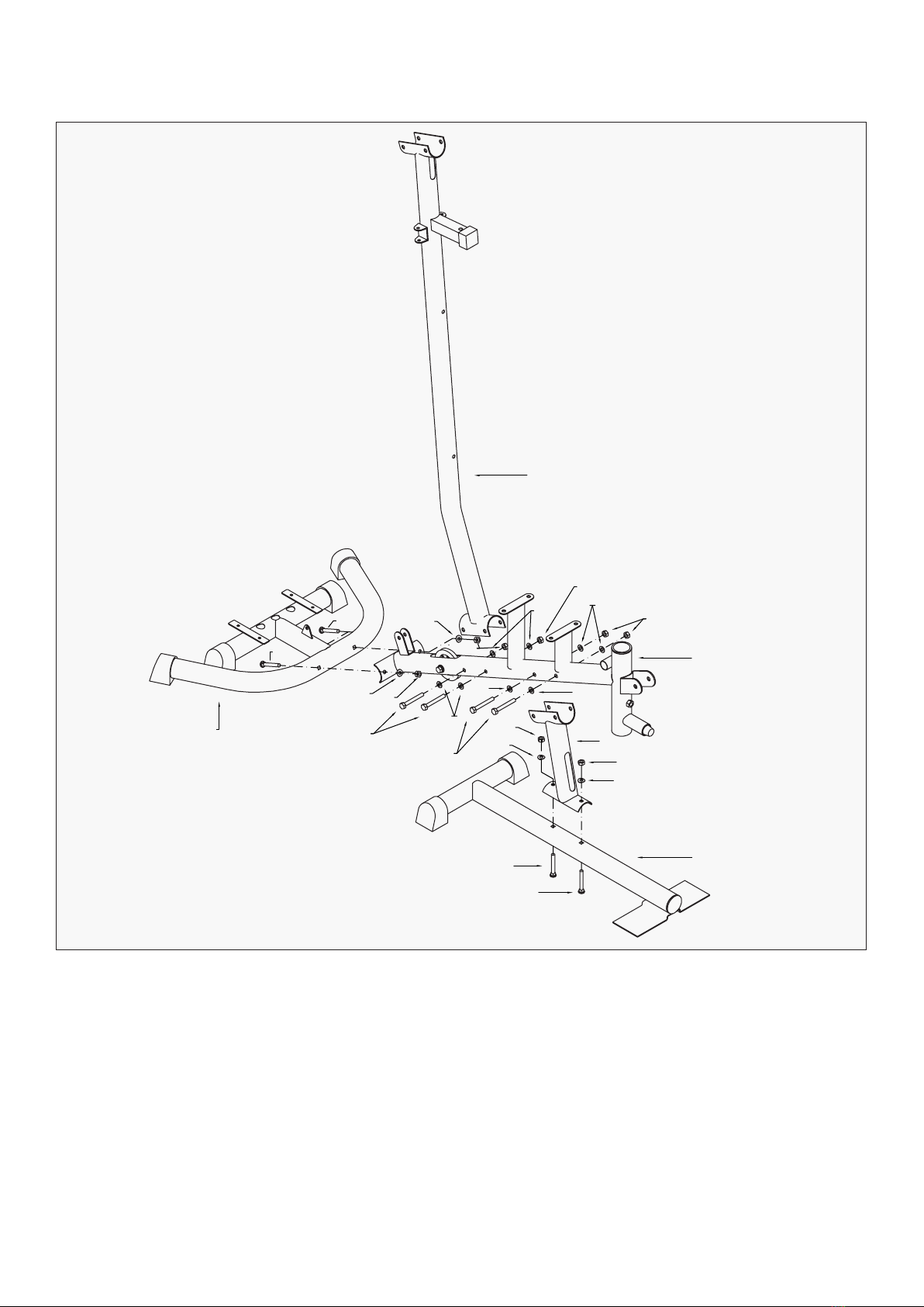
1Base Frame 1
2Seat post 1
3Rear Stabilizer 1
4Seat Support Tube 1
5Upright Support Tube 1
6Leg Curl Tube 1
7Guiding Tube 2
8Bridge Tube 1
9Pull unit 1
10L Butterfly Arm - Left 1
10R Butterfly Arm - Right 1
11 Handlebar 2
12 Lat Bar 1
13 Lower Pull Bar 1
14 Foam Tube for Leg curl 2
15 Bracket for Seat/Backrest 2
16 Hex Head Bolt M12X108 mml 2
17 Bracket for Pulley 2
18 Two Way Bracket for Pulley 1
19 Select Bar 1
20 Pulley Bracket 2
21 Axle for Pull Unit 1
22 Hex Head Bolt M8 x 20mmL 10
23 Hex Head Bolt M10 x 60mmL 2
24 Hex Head Bolt M8 x 15mmL 18
25 Hex Head Bolt M10 x 40mmL 9
26 Hex Head Bolt M10 x 45mmL 1
27 Hex Head Bolt M10 x 75mmL 4
28 Hex Head Bolt M10 x 70mmL 1
29 Hex Head Bolt M12x 75mmL 1
30 Hex Head Bolt M10 x 80mmL 7
31 Powder Metal Ring φ12 4
31A Powder Metal Ring φ16 2
32 Select Pin 1
33 Curve Washer OD22XID8.3 10
34 Curve Washer OD23XID10.3 6
35 Flat Washer OD23XID10.3 20
35A Flat Washer OD23XID8.3 20
36 Flat Washer OD24XID12.3 8
37 Flat Washer OD40XID12.5 2
Part No. Description Qty.
38 M8 Nylon Nut 2
39 M10 Nylon Nut 26
40 M12 Nylon Nut 6
41 Fixed Pin for Weight Stack 1
42 End Cap 6
43 φ60 Round Cap 2
44 φ60 Flat Cap 2
45 φ50.8 Flat Cap 8
46 φ25.4 Flat Cap 6
47 Pin 1
48 Rubber Ring 2
49 Pulley 11
49A Pulley A 1
50 Cap for Small Pulley 2
51 Plastic Bushing 4
52 Rubber Stopper 1
53 Foam for Butterfly Arm 2
54 Foam for Leg Curl 4
55 Foam for Handlebar 2
56 Hand Grip 4
57 Bushing for Weight Stack 1
58 Round Cap for Select Bar 1
59 Beck cushion 1
60 Seat 1
61 Chain 6 Links 2
62 Hook 5
63 Weight Stack 8 Lbs 1
64 Weight Stack 10 Lbs 9
65 Cable for Lat Bar 1
66 Cable for Butterfly Arm 1
67 Cable for Lower Pull Bar 1
68 Cushion Support tube 1
69 Bushing 1
70 Rubber Stopper 1
71 Knob 1
72 Elbow Cushion 1
73 Bracket for Cloth Cover 4
74 Spring 1
75 Cloth Cover for Left/Right 2
76 Plum-nut 1