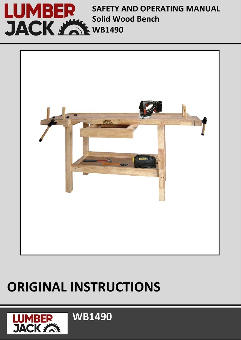
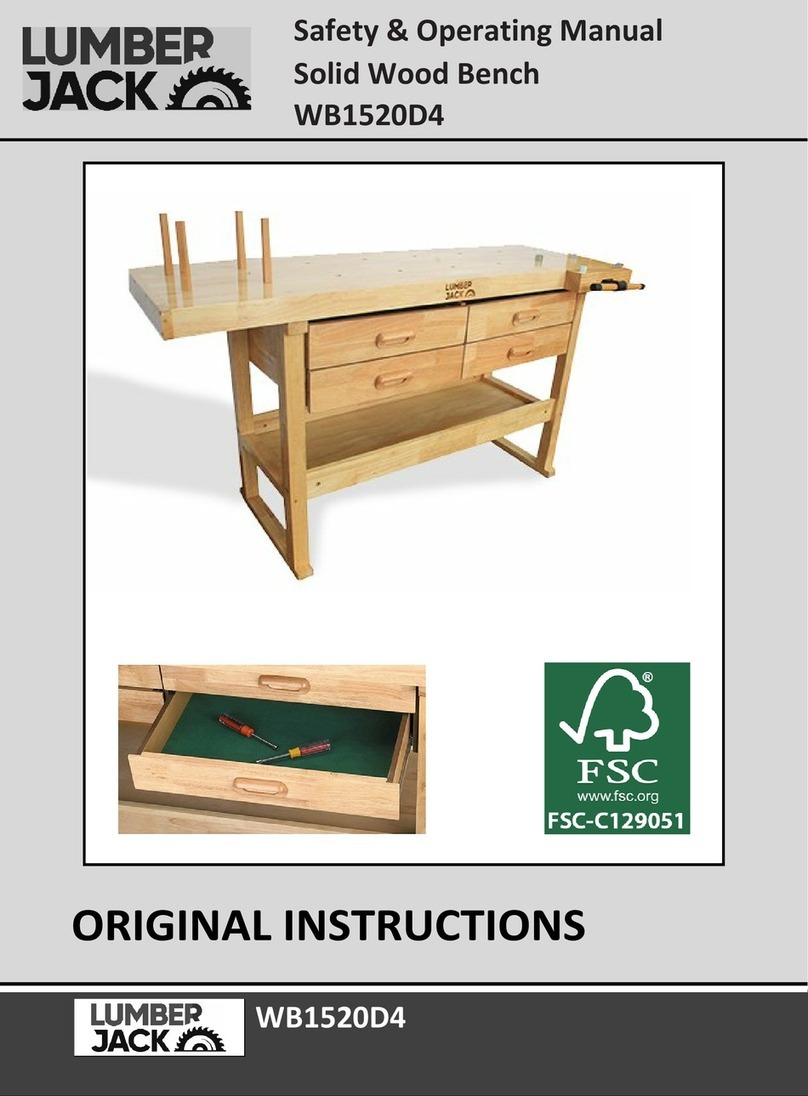
Lumberjack WB1620 Installation manual

WB1620
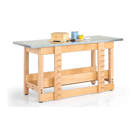
Solid Hardwood Work Bench
WB1620
ORIGINAL INSTRUCTIONS
SAFETY AND OPERATING MANUAL

WB1620
TABLE OF CONTENTS
Welcome to Lumber
j
ack!
Dear Customer, Congratulations on your purchase. Before using the
product for the first time please be sure to read these instructions for use.
They provide you with all information necessary for using the product safely and to
ensure its long service life.
Closely observe all safety information in these instructions!
General Tool Safety Warnings…………………………………………….…......01
Machine Details and Product Features……….…………………………….….02
Assembly……………………………………………………………………………………..03
Parts List/Parts Diagram……………………………………….………………..……08

WB1620 01
GENERAL TOOL SAFETY WARNINGS
WARNING Read all safety warnings and
all instructions.
Failure to follow the warnings
and instructions may result in serious injury.
Save all warnings and instructions for
future reference.
a) Do not exceed weight capacities for the
Workbench shelves and drawers. Be aware of
dynamic loading! Sudden load movement may
briefly create excess load causing product
failure.
b) Use only on flat, level and hard surface
capable of supporting the Workbench and any
item(s) placed on Workbench. Evenly distribute
load on Table to avoid tipping.
c) Use as intended only. Do not use Workbench
to perform task for which it was not designed.
d) For indoor use only.
e) Assemble only according to these instructions.
Improper assembly can create hazards.
f) Wear ANSI-approved safety goggles and
heavy-duty work gloves during assembly and
use.
g) Keep assembly area clean and well lit.
h) Keep bystanders out of the area during
assembly.
i) Do not assemble when tired or when under
the influence of drugs or medication.
j) This product is not a toy. Do not allow children
to play with, on or near Workbench.
k) Inspect before every use; do not use if parts
are loose or damaged.

WB1620 02
MACHINE DETAILS AND PRODUCT FEATURES
Machine Details
Specifications:
Vice capacity:7 Inch
Top shelf weight capacity:113kg
Drawer weight capacity:11kg(per drawer)
Bottom shelf capacity:90kg
Dimensions (Includes vice):
L 1620mm X W 510mm X H 860mm
Drawer inside dimensions(X2):
L 535mm X W 325mm X H 70mm
Product Features
1. Table Top x 1
2. Shelf x1
3. Cross Brace x 2
4. Leg x 2
5. Vice x 1
6. Screw(50mm) x 6
7. Bolt(60mm) x 8
8. Connecting Nut x 8
9. Hex Wrench(50mm) x 1
11. Anvil Peg x 4
12. Vice Screw and Washer x 1
13. Screw x 40
14. Sliding Partition x 1
15. Lower Support x 1
16. Drawer Front panel(P1) x 2
17. Drawer Back Panel (P2) x 2
18. Drawer Panel(P3) x 2
19. Drawer Slot Panel(P4) x 2
20. Drawer Bottom(P5) x 2
21. Drawer Handle x 2
22. Drawer Screw x 4

WB1620 03
ASSEMBLY
Assembly
Read the ENTIRE IMPORTANT
SAFETY INFORMATION section at the
beginning of this manual including all text
under subheadings therein before set up or
use of this product.
Note: For additional information regarding the
parts listed in the following pages, refer to Parts
List and Diagram on page 08.
Note: More than one person is needed for
proper assembly.
Note: In the supplied bag of hardware, the Nuts
are already threaded onto the Screw (6).
1.Insert Connecting Nuts (8) into holes at end of
Cross Braces (3). Make sure that the slot on the
Nuts align horizontally with the Bolts (7). This
will allow the Bolts to be threaded into the Cross
Braces.
2.Set the Cross Brace against a Leg (4) and use
the Hex Wrench (9) and Bolt (7) to fasten Cross
Brace and Leg together.
NOTE: Make sure the groove in the Cross Brace
is facing IN SEE Figures A and B.
3.Once both Legs have been fastened to the Cross
Brace, slide the Shelf (2) above against the Legs so
that the far edge fits onto the groove on the Cross
Brace. See Figure C, right.
4.While your assistant is holding the Shelf in place
against the first Cross Brace, set the second Cross
Brace against the other edge of the Shelf.
5.Once the Cross Brace is in place and the
mounting holes on the Legs are aligned with the
Connecting Nuts in the Cross Brace, use the Hex
Wrench and Bolts to fasten the second Cross Brace
to Legs.
With your assistant’s help, place the Table Top (1)
face down on a smooth, padded surface. This will
allow you to install the sliding drawers.
Note: When setting down the assembled Legs
onto the Table Top, verify both Legs and Table Top
are facing the correct direction. (Note the small
“Front” labels placed on the items. These labels
can be removed after assembly.)
WB1620 04
ASSEMBLY
6.Set the Sliding Partition (14) into place by
inserting the tabs at the end of the Partition into
the holes at the center of the Table Top’s
underside.
Note: Verify that the Sliding Partition and Table
Top face the same direction.
7.Use the Screws (13) to fasten the Sliding
partition to the middle of the Table Top’s
underside.
Note: There are no pilot holes available for this
step, so you will need to use a drill to make the
pilot holes before threading in Screws.
8. Using assistance, set the assembled Legs and
Shelf onto the underside of the Table Top.
Note: Verify that the Drawer guide slots on the
Sliding Partition face the same way as the Drawer
guide slots on the Legs.
9. Use the Hex Wrench and Screws (6) to fasten
the tops of the Legs to the Table Top underside.

WB1620 05
ASSEMBLY
10. Use the Hex Wrench and Screws (13) to
fasten the sides of the Legs to the Table Top
underside.
Note: There are no pilot holes available for this
step, so you will need to use a drill to make the
pilot holes before threading in Screws.
11. Set the Lower Support (15) across the top of
the Sliding Partition and against the sides of the
Legs. Then use Screws (6) to fasten each end of
the Lower Support to the sides of the Legs.
12. Once the ends of the Lower Support have been
fastened to the Legs, use the Screws (6) to fasten
the middle of the Lower Support to the top of the
Sliding Partition.
13. With assistance, set the assembled frame
right-side up and in the spot where you want the
Workbench located.
14. Remove the Vice Screw and Washer (12) from
the middle thread of the Vice (5).

WB1620 06
ASSEMBLY
15. Once the Vice Screw and Washer are removed,
slide the Vice into the three holes on the side of the
Workbench. Once the Vice is threaded into the holes
halfway, use the Hex Wrench to tighten the screws
on either side of the Vice’s center thread.
16. Use the Vice handle to thread in the Vice all the
way and reinstall the Vice Screw and Washer. This
will keep the Vice locked on place on the side of the
Workbench.
17. Use the Drawer Screws (22) to fasten the Drawer
Handles (21) to the Drawer Front Panels (16).
Note: Each Drawer piece should have a sticker
designating what it is (P1-P5). Use the Parts List as on
page 10 as reference. This will help assure correct
assembly.
18. Fasten the Drawer Panel (18) and the Drawer Slot
Panel (19) to the Drawer Front Panel.
19. Fasten the Drawer Back Panel to the ends of the
two side Panels. Then slide the Drawer Bottom (20)
into the grooves along the insides of the side panels,
making sure the felt side is up.
20. Fasten Drawer Bottom to Drawer Pack Panel. Once
Drawers are fully assembled, verify that the inside
tracks along the Sliding Partition are pushed forward.

WB1620 07
ASSEMBLY
21. Slide Drawers into tracks along Sliding Partition
and insides of the Legs.
22. Once all Drawers are inserted, tap Wood Pegs
(10) and Small Anvil Pegs (11) into desired holes on
the Table Top.
The Workbench is now fully assembled and ready for
use.

AIR6V 01AIR6V 01AIR6V 01
WB1620 08
No. Description No. Description
1 Table Top 13 Screw
2 Shelf 14 Sliding Partition
3 Cross Brace 15 Lower Support
4 Leg 16 Drawer Front Panel(P1)
5 Vice 17 Drawer Back Panel(P2)
6 Screw 18 Drawer Panel (P3)
7 Bolt 19 Drawer Slot Panel (P4)
8 Connecting Nut 20 Drawer Bottom (P5)
9 Hex Wrench (50mm) 21 Drawer Handle
11 Anvil Peg 22 Drawer Screw
12 Vice Screw and Washer
PARTS LIST/ PARTS DIAGRAM

Table of contents
Other Lumberjack Tools Storage manuals