manuals.online logo
Brands
  1. Home
  2. •
  3. Brands
  4. •
  5. Luverne
  6. •
  7. Automobile Accessories
  8. •
  9. Luverne 571477 User manual

Luverne 571477 User manual

LUVERNETRUCK.COM •PRODUCT SUPPORT: 877.287.8634 •571477-INS-RA •10/27/2020 •ECN7528 •PAGE 1
Product Registration and Warranty
LUVERNE stands behind our products with industry-leading warranties. To get copies of the product
warranties, register your purchase or provide feedback, visit: warranty.curtgroup.com/surveys
INSTALLATION MANUAL 571477
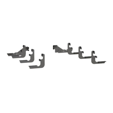
Parts List
Qty Description
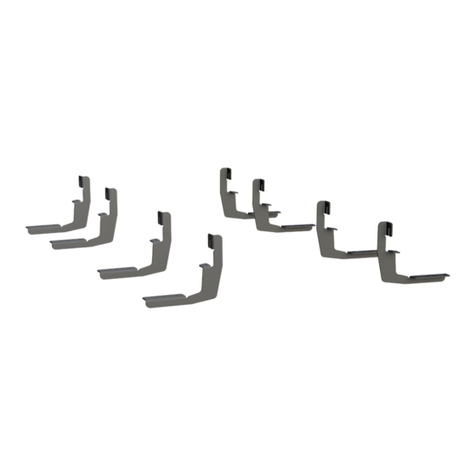
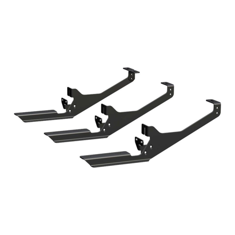
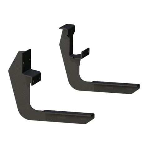
1Mounting bracket, driver-side front
1Mounting bracket, driver-side middle
1Mounting bracket,
passenger-side front
1Mounting bracket,
passenger-side middle
3Mounting bracket,
passenger-side rear
5Retainer plate, long
2Retainer plate, short
14 Flat washer, 5/16"
14 Hex bolt, 5/16"-18 x 1", grade 5
14 Flange nut, 5/16"-18
4Flat washer, 1/4"
4Hex bolt, 1/4"-20 x 3/4", grade 5
4Clip-on nut, 1/4"-20
13 Thread forming bolt, 5/16" x 3/4"
Tools Required
Drill Clamp
Drill bit, 3/16" Wrench, 1/2"
Drill bit, 11/32" Straight edge / level
Ratchet Paint marker
Socket, 7/16" Tape measure
Socket, 1/2" Trim panel pry tool
Maintenance
Mild automotive detergent may be used to clean the product. Do not use dish detergent, abrasive
cleaners, abrasive pads, wire brushes or other similar products that may damage the finish.
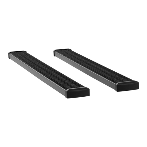
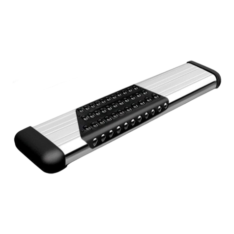
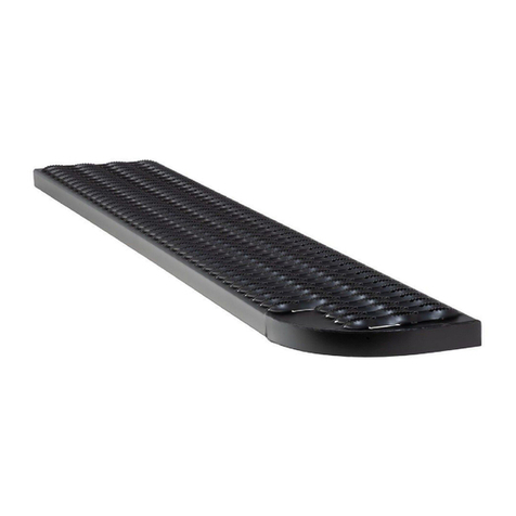
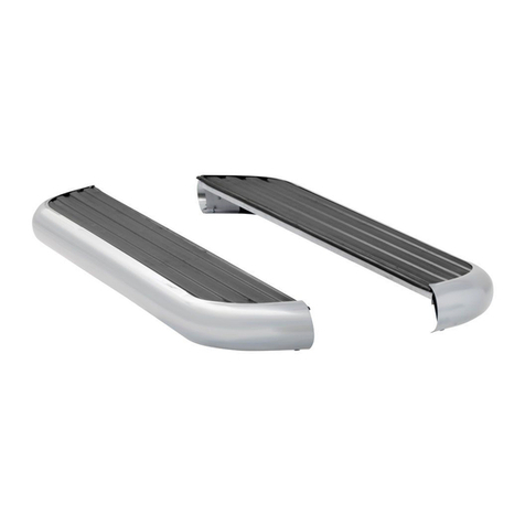
Product Photo
Front
Rear
Torque Specifications
1/4" bolt 3 ft-lbs.
5/16" bolt 7 ft-lbs.
Use above torque setting unless otherwise noted
Level of Difficulty
Moderate
Installation difficulty levels are based on time
and effort involved and may vary depending on
the installer level of expertise, condition of the
vehicle and proper tools and equipment.
NOTICE
Visit www.luvernetruck.com for a full-color copy of this
instruction manual, as well as helpful videos, guides and much more!
Before you begin installation, read all instructions thoroughly.
Proper tools will improve the quality of installation and reduce the time required.
Periodic inspection of your product should be performed
to ensure all hardware and / or components remain secure.
To help prevent damage to the product or vehicle, refer to the specified
torque specifications when securing hardware during the installation process.
This is the first of two manuals
required to complete this installation.
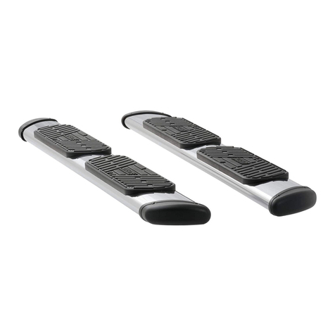
The second manual is included with
your side steps / running boards.
LUVERNETRUCK.COM •PRODUCT SUPPORT: 877.287.8634 •571477-INS-RA •10/27/2020 •ECN7528 •PAGE 2
Step 1 - Driver-Side
As shown, mark the pinch weld for the front
hole of each bracket. The holes will be 7" back
from the wheel well for the front bracket and
34-3/8” back for the rear bracket.
Step 4 - Driver-Side
Place the second bracket up to the inside of the
pinch weld, lined up with the second marked
hole, and secure it using a clamp. Note: Some
under coating will need to be scraped off so the
bracket will sit flat with the pinch weld.
Using the bracket holes as a reference, mark
the center of the two holes on the pinch weld
and the two holes on the angled surface that
match up closest to the body plug.
Step 2 - Driver-Side
Attach the front driver side bracket by lining up the bracket
with the first marked spot, then mark the second pinch weld hole.
Make sure to leave enough space at the top of the pinch weld for
the retainer and hardware to sit flat against the outside pinch weld.
Step 3 - Driver-Side
After the holes are marked, drill an
11/32" hole at each marked location.
Fasten the bracket to the pinch weld using
the provided 5/16"-18 hardware and retainer
plate. The top hole will be drilled later in the
installation.
7"
34-3/8"
LUVERNETRUCK.COM •PRODUCT SUPPORT: 877.287.8634 •571477-INS-RA •10/27/2020 •ECN7528 •PAGE 3
Step 5 - Driver-Side
Once the four holes have been marked, drill
the two pinch welds and the marked hole,
toward the rear of the vehicle on the angled
surface, with an 11/32" bit.
Drill the last hole toward the front of the vehicle
on the angled surface with a 3/16" drill bit.
Step 8 - Driver-Side & Passenger-Side
Remove the body plug next to the 11/32” hole
and install a U-nut. Reinstall the bracket and
use a 1/4” bolt and washer in the U-nut. If the
optional hole was drilled, use a 5/16” x 3/4”
self-tapping screw. Tighten all hardware to the
recommended torque specifications on page 1.
Repeat steps 1 - 8 to install the
front two passenger-side brackets.
Step 6 - Driver-Side
Remove the body plug on the angled surface,
toward the rear of the vehicle, that the 11/32"
hole should have been drilled next to. Slide
the U-nut in place over the 11/32" hole.
Place the bracket into position and fasten it to
the pinch weld using the provided 5/16" bolts,
washers, nuts and retainer plate. Do not fully
tighten at this time.
Insert a 1/4” bolt and flat washer into the U-nut
bracket hole and the 5/16” x 3/4” self-tapping
screw through the 3/16” hole. Tighten all
hardware securing the second bracket.
Step 7 - Driver-Side
Drill the top hole of the front bracket by placing
a straight edge or level on the flat surface of
the second bracket, and adjusting the front
bracket until the straight edge is sitting level
with the vehicle. Mark the center of the top
slotted hole.
Remove the bracket and drill an 11/32” hole
where marked. Optional: Before removing the
bracket, the center of the extra hole can be
marked and drilled with a 3/16” bit.
LUVERNETRUCK.COM •PRODUCT SUPPORT: 877.287.8634 •571477-INS-RA •10/27/2020 •ECN7528 •PAGE 4
Step 11 - Passenger-Side
Reattach the brackets to the pinch weld and
use a 5/16” x 3/4” self-tapping screw for
each upper hole. Tighten all hardware to the
recommended torque specifications on page 1.
Note: To complete the installation,
refer to the manual included with
your running boards / side steps.
Step 10 - Passenger-Side
Using the running board or a level, align each
of the three rear brackets with the first two
brackets and mark one of the three top holes.
Additional holes can be marked, but are
optional. Remove the brackets and drill
each marked hole with a 3/16” drill bit.
Step 9 - Passenger-Side
Measure from the front wheel well and mark
the front hole for the three rear brackets:
First hole: 48-7/8”
Second hole: 66-7/8”
Third hole: 95-7/8”
Place a bracket at each location and mark
the second pinch weld hole. Drill all marked
locations with a 11/32” bit. After the holes
are drilled attach the brackets to the pinch
weld with the provided 5/16” bolts, washers,
nuts and retainer plates.
X =48-7/8" X
95-7/8"
66-7/8"

Other Luverne Automobile Accessories manuals

Luverne 571134 User manual

Luverne

Luverne 571134 User manual

Luverne 495154 User manual

Luverne

Luverne 495154 User manual

Luverne Regal 7 477078 User manual

Luverne

Luverne Regal 7 477078 User manual

Luverne 571729 Datasheet

Luverne

Luverne 571729 Datasheet

Luverne 251124 User manual

Luverne

Luverne 251124 User manual

Luverne O-MEGA II Datasheet

Luverne

Luverne O-MEGA II Datasheet

Luverne 570231 User manual

Luverne

Luverne 570231 User manual

Luverne 415078 User manual

Luverne

Luverne 415078 User manual

Luverne 570747 User manual

Luverne

Luverne 570747 User manual

Luverne 431411 Datasheet

Luverne

Luverne 431411 Datasheet

Luverne 400940 User manual

Luverne

Luverne 400940 User manual

Luverne 571726 User manual

Luverne

Luverne 571726 User manual

Luverne 401529 User manual

Luverne

Luverne 401529 User manual

Luverne 206620 User manual

Luverne

Luverne 206620 User manual

Luverne 205760 User manual

Luverne

Luverne 205760 User manual

Luverne O-MEGA II 583036 Datasheet

Luverne

Luverne O-MEGA II 583036 Datasheet

Luverne O-MEGA II Series Datasheet

Luverne

Luverne O-MEGA II Series Datasheet

Luverne 4055122 User manual

Luverne

Luverne 4055122 User manual

Luverne 401800 User manual

Luverne

Luverne 401800 User manual

Luverne 401445 User manual

Luverne

Luverne 401445 User manual

Luverne 416088 User manual

Luverne

Luverne 416088 User manual

Luverne 415254 User manual

Luverne

Luverne 415254 User manual

Luverne 330750 User manual

Luverne

Luverne 330750 User manual

Popular Automobile Accessories manuals by other brands

MovaNext Lux user manual

MovaNext

MovaNext Lux user manual

Sonorix A1 user manual

Sonorix

Sonorix A1 user manual

Cequent Performance Products 24876 installation instructions

Cequent Performance Products

Cequent Performance Products 24876 installation instructions

Safe Fleet Prime Design VRR FT31B Assembly instructions

Safe Fleet

Safe Fleet Prime Design VRR FT31B Assembly instructions

Whispbar K918W Fitting instructions

Whispbar

Whispbar K918W Fitting instructions

Whispbar K386W Fitting Instructions for Basic Carrier

Whispbar

Whispbar K386W Fitting Instructions for Basic Carrier

Car-Interface v.LiNK CI-VL2-PC-HSD manual

Car-Interface

Car-Interface v.LiNK CI-VL2-PC-HSD manual

Hyundai 2S211AD00AL installation instructions

Hyundai

Hyundai 2S211AD00AL installation instructions

Prorack K814 instructions

Prorack

Prorack K814 instructions

JL Audio 13W7-D1.5 owner's manual

JL Audio

JL Audio 13W7-D1.5 owner's manual

Active Controls ActiveStart ACS20WS Installation, operation & application guide

Active Controls

Active Controls ActiveStart ACS20WS Installation, operation & application guide

AEV FRONT SKID RAM HEAVY DUTY installation guide

AEV

AEV FRONT SKID RAM HEAVY DUTY installation guide

curt 16993 installation manual

curt

curt 16993 installation manual

Dakota Digital HDX-61C-IMP Instrument Installation

Dakota Digital

Dakota Digital HDX-61C-IMP Instrument Installation

Twiins HANDSFREE 2.0 instruction manual

Twiins

Twiins HANDSFREE 2.0 instruction manual

Axxess AXAC-MZ1 installation instructions

Axxess

Axxess AXAC-MZ1 installation instructions

Motorola 6803578F42 user manual

Motorola

Motorola 6803578F42 user manual

Prorack K469 Fitting instructions

Prorack

Prorack K469 Fitting instructions

manuals.online logo
manuals.online logoBrands
  • About & Mission
  • Contact us
  • Privacy Policy
  • Terms and Conditions

Copyright 2025 Manuals.Online. All Rights Reserved.