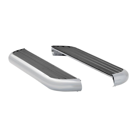
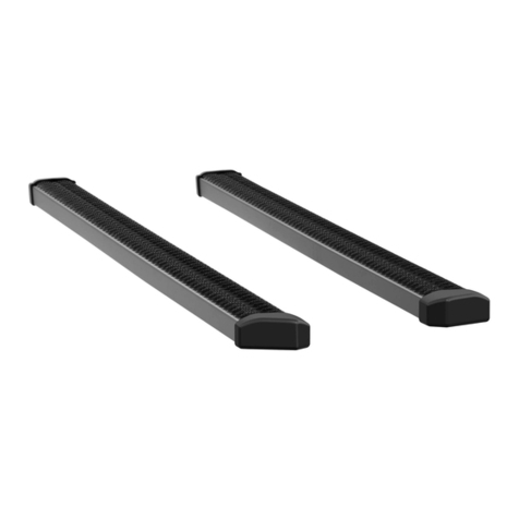
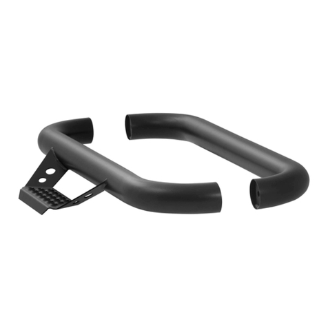
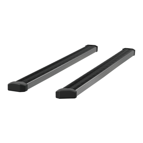
manuals.online logo
Brands
  1. Home
  2. •
  3. Brands
  4. •
  5. Luverne
  6. •
  7. Automobile Accessories
  8. •
  9. Luverne 571726 User manual

Luverne 571726 User manual

LUVERNETRUCK.COM •NEED ASSISTANCE? •8 7 7. 2 8 7. 8 6 3 4 •571726-INS-RA •PAGE 1
INSTALLATION MANUAL 571726
Tools Required
Socket, 1/2" Drill bit, 3/8"
Wrench, 1/2" Drill bit, 3/32"
Flathead
screw driver
Drill bit, 19/64"
Marker Putty knife
Maintenance
To protect the product, wax after installing. Regular waxing is recommended
to add a protective layer over the finish. Do not use any type of polish or wax
that may contain abrasives that could damage the finish.
For polished, gloss and other smooth finishes,
polish may be used to clear small scratches and scuffs on the finish.
Mild automotive detergent may be used to clean the product. Do not use dish detergent, abrasive
cleaners, abrasive pads, wire brushes or other similar products that may damage the finish.
Product PhotoLevel of Difficulty
Easy
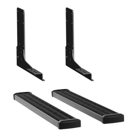
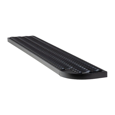
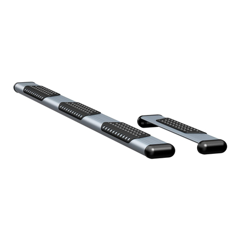
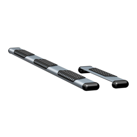
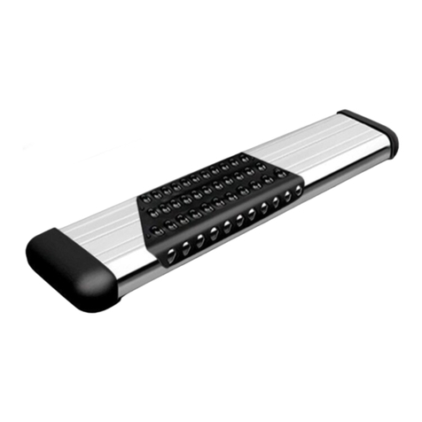
This is the first of two manuals
required to complete this installation.
The second manual is included with
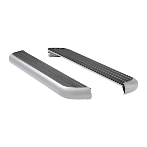
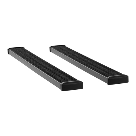
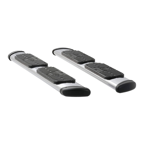
your side steps / running boards.
NOTICE
Before you begin installation, read all instructions thoroughly.
Proper tools will improve the quality of installation and reduce the time required.
To help prevent damage to the product or vehicle, refer to the specified
torque specifications when securing hardware during the installation process.
Torque Specifications
Metric
M6 bolt 3 ft-lbs.
M8 bolt 7 ft-lbs.
M10 bolt 16 ft-lbs.
M12 bolt 28 ft-lbs.
SAE
1/4" bolt 3 ft-lbs.
5/16" bolt 7 ft-lbs.
3/8" bolt 16 ft-lbs.
7/16" bolt 20 ft-lbs.
1/2" bolt 28 ft-lbs.
Use above torque setting unless otherwise noted
Product Registration and Warranty
CURT Group stands behind our products with industry-leading warranties.
Provide feedback and help us to improve our products by registering your purchase at:
warranty.curtgroup.com/surveys
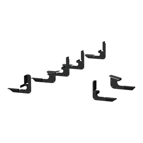
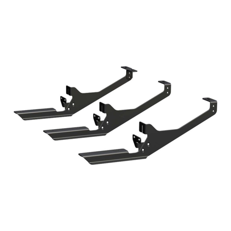
Parts List
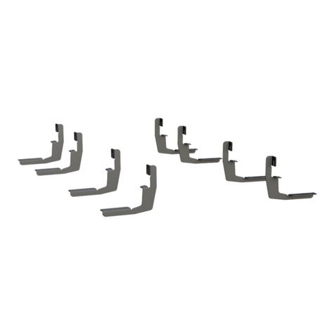
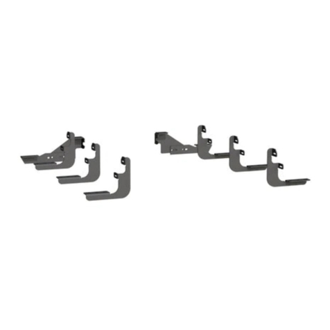
1Front mounting bracket
1 AC mounting top bracket
1 AC mounting bracket
2Bolt retainer
6Lock washer, 5/16"
2Flat washer, 5/16"
2Thread-cutting screw, 5/16"
1U-bolt 3"
6Bolt, M8
4Clip nut, M8
4Flange nut, M8
LUVERNETRUCK.COM •NEED ASSISTANCE? •8 7 7. 2 8 7. 8 6 3 4 •571726-INS-RA •PAGE 2
Step 1
Starting on the driver side, measure back from
the rear edge of the front wheel opening and
make a mark at 8-3/4" and 30-5/8". These will
be the mounting locations for the front hole on
each mounting bracket.
Note: Dimensions may need to be
adjusted forward or backward to avoid
drilling through spot welds in the pinch seam.
Step 4
Drill a 3/32" pilot hole in each of
the marked locations. Enlarge each
hole using a 3/8" drill bit.
Note: Place a putty knife between the
pinch weld and the rocker molding to
avoid damaging molding from drilling.
Step 2
Hold each bracket in its mounting
location and mark each hole on the
rocker panel and pinch weld.
Step 3
From the underside of the plastic rocker
molding, use a flathead screwdriver to
release the rocker molding retaining pins.
Note:
Do not fully remove the rocker molding,
as this will damage the trim and require
replacement. Only remove the retaining pins.
LUVERNETRUCK.COM •NEED ASSISTANCE? •8 7 7. 2 8 7. 8 6 3 4 •571726-INS-RA •PAGE 3
Step 5
Install the U-bolt into the top two holes
by inserting the threaded side first through
one hole, then back out through the other hole.
Secure with the plastic bolt retainers.
Slide two clip nuts onto the pinch seam
over the bottom two holes. Secure the front
mounting bracket to the U-bolt with 5/16"
flat washers and flange nuts. Secure the
clip nuts with 5/16" lock washers and M8 bolts.
Snug the hardware,
but do not fully tighten.
Step 8
Drill a 3/32" pilot hole in each location.
Enlarge the upper two holes using a
19/64" drill bit, and enlarge the pinch
seam holes using a 3/8" drill bit.
Step 6
Assemble the AC bracket using two
M8 bolts, flat washers and flange nuts.
Step 7
Using the measurements from step 1,
locate the bracket and mark all four hole
locations on the rocker panel.
19/64"
19/64"
3/8" 3/8"
LUVERNETRUCK.COM •NEED ASSISTANCE? •8 7 7. 2 8 7. 8 6 3 4 •571726-INS-RA •PAGE 4
Step 9
Slide two clip nuts onto the pinch seam
over the bottom two holes. Secure the AC
bracket using two thread-cutting bolts and
5/16" flat washers in the top two holes, and
two M8 bolts and lock washers in the pinch
seam holes.
Note: To complete the installation,
refer to the manual included with
your side steps / running boards.

Other Luverne Automobile Accessories manuals

Luverne O-MEGA II 583036 Datasheet

Luverne

Luverne O-MEGA II 583036 Datasheet

Luverne 431411 Datasheet

Luverne

Luverne 431411 Datasheet

Luverne 570231 User manual

Luverne

Luverne 570231 User manual

Luverne 570747 User manual

Luverne

Luverne 570747 User manual

Luverne 415254 User manual

Luverne

Luverne 415254 User manual

Luverne 416088 User manual

Luverne

Luverne 416088 User manual

Luverne 206620 User manual

Luverne

Luverne 206620 User manual

Luverne 571729 Datasheet

Luverne

Luverne 571729 Datasheet

Luverne 571477 User manual

Luverne

Luverne 571477 User manual

Luverne 401445 User manual

Luverne

Luverne 401445 User manual

Luverne 400940 User manual

Luverne

Luverne 400940 User manual

Luverne 415078 User manual

Luverne

Luverne 415078 User manual

Luverne Regal 7 477078 User manual

Luverne

Luverne Regal 7 477078 User manual

Luverne 4055122 User manual

Luverne

Luverne 4055122 User manual

Luverne 251124 User manual

Luverne

Luverne 251124 User manual

Luverne 330750 User manual

Luverne

Luverne 330750 User manual

Luverne 495154 User manual

Luverne

Luverne 495154 User manual

Luverne 571134 User manual

Luverne

Luverne 571134 User manual

Luverne 401800 User manual

Luverne

Luverne 401800 User manual

Luverne O-MEGA II Series Datasheet

Luverne

Luverne O-MEGA II Series Datasheet

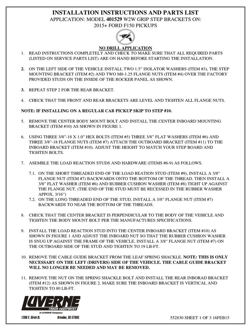
Luverne 401529 User manual

Luverne

Luverne 401529 User manual

Luverne 205760 User manual

Luverne

Luverne 205760 User manual

Luverne O-MEGA II Datasheet

Luverne

Luverne O-MEGA II Datasheet

Popular Automobile Accessories manuals by other brands

LSD-Doors 500 60 001 installation instructions

LSD-Doors

LSD-Doors 500 60 001 installation instructions

Vauxhall New Crossland Multimedia Navi Pro Infotainment manual

Vauxhall

Vauxhall New Crossland Multimedia Navi Pro Infotainment manual

Westfalia 11 43 55 instruction manual

Westfalia

Westfalia 11 43 55 instruction manual

tams elektronik FCS Series manual

tams elektronik

tams elektronik FCS Series manual

FIA TR47-23 Installation instructions manual

FIA

FIA TR47-23 Installation instructions manual

Fieryred 93S-FS7S-UFA2 instructions

Fieryred

Fieryred 93S-FS7S-UFA2 instructions

STO N SHO SNS 137 Installation procedures

STO N SHO

STO N SHO SNS 137 Installation procedures

Solight BT01 user manual

Solight

Solight BT01 user manual

AMiO SSR-01L user manual

AMiO

AMiO SSR-01L user manual

BD Diesel Performance Monitor Cool Engine Shutdown installation instructions

BD Diesel Performance

BD Diesel Performance Monitor Cool Engine Shutdown installation instructions

Smittybilt D8545 installation instructions

Smittybilt

Smittybilt D8545 installation instructions

Racepak IQ3 Drag Dash installation manual

Racepak

Racepak IQ3 Drag Dash installation manual

MAY MP9254 Fittings guide

MAY

MAY MP9254 Fittings guide

Whelen Engineering Company FastTrax FTF2 installation guide

Whelen Engineering Company

Whelen Engineering Company FastTrax FTF2 installation guide

Honeywell Thor VM2W user guide

Honeywell

Honeywell Thor VM2W user guide

Metra Electronics 99-7388HG installation instructions

Metra Electronics

Metra Electronics 99-7388HG installation instructions

Edscha Trailer Systems Curtain Sider-UL/HD quick guide

Edscha Trailer Systems

Edscha Trailer Systems Curtain Sider-UL/HD quick guide

AA Products AX312 WHT Series instruction manual

AA Products

AA Products AX312 WHT Series instruction manual

manuals.online logo
manuals.online logoBrands
  • About & Mission
  • Contact us
  • Privacy Policy
  • Terms and Conditions

Copyright 2025 Manuals.Online. All Rights Reserved.