manuals.online logo
Brands
  1. Home
  2. •
  3. Brands
  4. •
  5. M-system
  6. •
  7. Control Unit
  8. •
  9. M-system R3-AR4 User manual

M-system R3-AR4 User manual

5-2-55, Minamitsumori, Nishinari-ku, Osaka 557-0063 JAPAN
Phone: +81(6)6659-8201 Fax: +81(6)6659-8510 E-mail: info@m-system.co.jp
EM-8433 Rev.3 P. 1 / 4
INSTRUCTION MANUAL
RTD INPUT ALARM MODULE
(4 points, isolated) MODEL R3-AR4
BEFORE USE ....
Thank you for choosing M-System. Before use, please check
contents of the package you received as outlined below.
If you have any problems or questions with the product,
please contact M-System’s Sales Office or representatives.
■PACKAGE INCLUDES:
RTD input alarm module....................................................(1)
■MODEL NO.
Confirm Model No. marking on the product to be exactly
what you ordered.
■INSTRUCTION MANUAL
This manual describes necessary points of caution when
you use this product, including installation, connection and
basic maintenance procedures.
POINTS OF CAUTION
■CONFORMITY WITH EU DIRECTIVES
• The equipment must be mounted inside the instrument
panel of a metal enclosure.
• The actual installation environments such as panel con-
figurations, connected devices, connected wires, may af-
fect the protection level of this unit when it is integrated
in a panel system. The user may have to review the CE
requirements in regard to the whole system and employ
additional protective measures to ensure the CE conform-
ity.
■HOT SWAPPABLE MODULES
• Replacing the module does not affect other modules on
the same base. Thus, the module can be replaced while
the power is ON. However, replacing multiple modules
at once may greatly change live voltage levels. We highly
recommend to replace them one by one.
■GENERAL PRECAUTIONS
• DO NOT set the switches on the module while the power
is supplied. The switches are used only for maintenance
without the power.
■ENVIRONMENT
• Indoor use.
• When heavy dust or metal particles are present in the
air, install the unit inside proper housing with sufficient
ventilation.
• Do not install the unit where it is subjected to continuous
vibration. Do not subject the unit to physical impact.
• Environmental temperature must be within -10 to +55°C
(14 to 131°F) with relative humidity within 30 to 90% RH
in order to ensure adequate life span and operation.
■WIRING
• Do not install cables close to noise sources (relay drive
cable, high frequency line, etc.).
• Do not bind these cables together with those in which
noises are present. Do not install them in the same duct.
■AND ....
• The unit is designed to function as soon as power is sup-
plied, however, a warm up for 10 minutes is required for
satisfying complete performance described in the data
sheet.
INSTALLATION
Use the Installation Base (model: R3-BSx).
R3-AR4
5-2-55, Minamitsumori, Nishinari-ku, Osaka 557-0063 JAPAN
Phone: +81(6)6659-8201 Fax: +81(6)6659-8510 E-mail: info@m-system.co.jp
EM-8433 Rev.3 P. 2 / 4
COMPONENT IDENTIFICATION
1
11
12
13
14
15
16
17
18
19
20
2
3
4
5
6
7
8
9
10
ON
8
7
6
5
4
3
2
1
SW1SW2
ON
8
7
6
5
4
3
2
1
SW3
ON
4
3
2
1
■FRONT VIEW ■SIDE VIEW
ERR LED
RUN LED
Conv.
Rate
Temp.
Unit
Input 2 (SW1)
or
Input 4 (SW2)
RTD
Input 1 (SW1)
or
Input 3 (SW2)
Burnout
Functions
■STATUS INDICATOR LED
RUN indicator: Bi-color (red/green) LED;
Red when the bus A operates normally;
Green when the bus B operates normally;
Amber when both buses operate normally.
ERR indicator: Bi-color (red/green) LED;
Red with burnout;
Green in normal operating conditions.
■SIDE DIP SW
(*) Factory setting
• RTD Type: SW1, SW2
INPUT 1 (SW1) INPUT 2 (SW1)
RTDINPUT 3 (SW2) INPUT 4 (SW2)
12345678
OFF OFF OFF OFF OFF OFF OFF OFF Pt 100 (*)
(JIS ’97, IEC)
ON OFF OFF OFF ON OFF OFF OFF Pt 100 (JIS ’89)
OFF ON OFF OFF OFF ON OFF OFF JPt 100 (JIS ’89)
ON ON OFF OFF ON ON OFF OFF Pt 50 Ω (JIS ’81)
OFF OFF ON OFF OFF OFF ON OFF Ni 100
ON OFF ON OFF ON OFF ON OFF Cu 10 @ 25°C
OFF ON ON OFF OFF ON ON OFF Pt 1000
ON ON ON OFF ON ON ON OFF Ni 508.4 Ω
OFF OFF OFF ON OFF OFF OFF ON Cu 50
• Burnout: SW3-1
SW3-1 BURNOUT
OFF Upscale (*)
ON Downscale
• Temperature Unit: SW3-2, 3-3
SW3-2 SW3-3 TEMP. UNIT
OFF OFF °C (*)
ON OFF °F
OFF ON (Absolute Temp)
• Conversion Rate: SW3-4
SW3-4 CONV. RATE
OFF 250 msec. (*)
ON 1 sec.
R3-AR4
5-2-55, Minamitsumori, Nishinari-ku, Osaka 557-0063 JAPAN
Phone: +81(6)6659-8201 Fax: +81(6)6659-8510 E-mail: info@m-system.co.jp
EM-8433 Rev.3 P. 3 / 4
TERMINAL CONNECTIONS
Connect the unit as in the diagram below.
■EXTERNAL DIMENSIONS unit: mm (inch)
1
11
12
13
14
15
16
17
18
19
20
2
3
4
5
6
7
8
9
10
130 (5.12)
27.5 (1.08) 109 (4.29) POSITIONING
GUIDE
TERMINAL
COVER
20–M3
SCREW
6.2
(.24)
■CONNECTION DIAGRAM
1
2
INPUT 1
3
4
INPUT 2
6
7
INPUT 3
8
9
INPUT 4
100Ω
11 13 16 18
• Unused Input Channels
Close across the unused input terminals with a resistor as
shown below and set the DIP switch for Pt 100 input.
Unused channels left open are equal to the burnout,
which turns the red ERR LED on and sets a burnout flag at
the PLC or the host device.
Connecting the resistor means approx. 0°C. An alarm
setpoint must be set to a value that does not trip an
unwanted alarm.
Unused channels can be specified and set so on the PC
Configurator Software (model: R3CON) without needing to
connect resistors at the field terminals.
A
B
B
RTD
1
2
11
3
4
13
6
7
16
8
9
18
*For dual redundant communication.
INPUT 1
A
B
B
A
B
B
A
B
B
RTD
INPUT 2
RTD
INPUT 3
RTD
INPUT 4
BUS CONNECTOR
INTERNAL POWER
INTERNAL BUS A
INTERNAL BUS B*
R3-AR4
5-2-55, Minamitsumori, Nishinari-ku, Osaka 557-0063 JAPAN
Phone: +81(6)6659-8201 Fax: +81(6)6659-8510 E-mail: info@m-system.co.jp
EM-8433 Rev.3 P. 4 / 4
ALARM SETTING
The following parameters are programmable using the PC
Configurator Software (model: R3CON).
■ALARM TRIP POINT
(-200.0 to +850.0°C or -328 to +1562°F; factory set to A1:
400.0°C, A2: 300.0°C, A3: 200.0°C, A4: 100.0°C)
Four alarm setpoints are selectable per each input.
■ALARM TYPE (High or Low; factory set to A1: High, A2:
High, A3: Low, A4: Low)
High or Low alarm is selectable for each alarm trip point.
High alarm: An alarm is set when the input signal goes
above the setpoint.
Low alarm: An alarm is set when the input signal goes be-
low the setpoint.
■DEADBAND (HYSTERESIS)
(0.00 to 100.0°C or 0 to 1800°F; factory set to 10.0°C or 100°F)
Deadband (deviation between the points where the alarm is
set and reset) is selectable for each alarm trip point.
■POWER ON DELAY TIME
(0.0 to 99.0 seconds; factory set to 5.0)
The alarm output start functioning in the preset time after
the power has been turned on.
This setting is common to all four points.
■ALARM ON DELAY TIME
(0.0 to 99.0 seconds; factory set to 1.0)
The alarm output is set when the preset time elapses after
the input has entered in the alarm range.
This setting is common to all four points.
■ALARM HOLD TIME
(0.0 to 99.0 seconds; factory set to 1.0)
The alarm output is held for the preset time even if it is
reset in shorter time.
This setting is common to all four points.
OUTPUT DATA DESCRIPTIONS
Four alarm setpoints are selectable per each input. One
(1) word (16 bit) data is transmitted to the PLC or the host
device via the R3 network module.
0
15
Alarm 1
Alarm 2 Input 1
Alarm 3
Alarm 4
Alarm 1
Alarm 2 Input 2
Alarm 3
Alarm 4
Alarm 1
Alarm 2 Input 3
Alarm 3
Alarm 4
Alarm 1
Alarm 2 Input 4
Alarm 3
Alarm 4
WIRING INSTRUCTIONS
■SCREW TERMINAL
Torque: 0.5 N·m
■SOLDERLESS TERMINAL
Refer to the drawing below for recommended ring tongue
terminal size. Spade tongue type is also applicable. Solder-
less terminals with insulation sleeve do not fit.
Applicable wire size: 0.3 – 0.75 mm2
Recommended manufacturer: Japan Solderless Terminal
MFG. Co., Ltd., Nichifu Co., Ltd.
12max
6max
3max 4min
3.2 dia.
(mm)

Other M-system Control Unit manuals

M-system 61A User manual

M-system

M-system 61A User manual

M-system M8CD1 User manual

M-system

M-system M8CD1 User manual

M-system R7L-RS4 User manual

M-system

M-system R7L-RS4 User manual

M-system R7M-EC8A/UL User manual

M-system

M-system R7M-EC8A/UL User manual

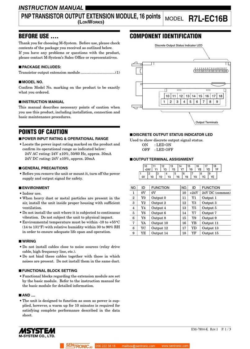
M-system R7L-EC16B User manual

M-system

M-system R7L-EC16B User manual
M-system 73VR3100 User manual

M-system

M-system 73VR3100 User manual

M-system R7M-EC8C User manual

M-system

M-system R7M-EC8C User manual

M-system R3-PS3 User manual

M-system

M-system R3-PS3 User manual
M-system R3-RS8 User manual

M-system

M-system R3-RS8 User manual

M-system M6SXF3 User manual

M-system

M-system M6SXF3 User manual

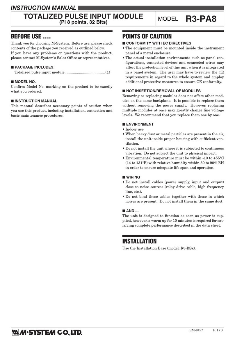
M-system R3-PA8 User manual

M-system

M-system R3-PA8 User manual
M-system R7D-MS4 User manual

M-system

M-system R7D-MS4 User manual

M-system R7HL-DC16B User manual

M-system

M-system R7HL-DC16B User manual

M-system R3-PA4B User manual

M-system

M-system R3-PA4B User manual

M-system R7M-DC16B User manual

M-system

M-system R7M-DC16B User manual

M-system R7D-EA16 User manual

M-system

M-system R7D-EA16 User manual

M-system R7C-EC8A/UL User manual

M-system

M-system R7C-EC8A/UL User manual

M-system R7D-EA8 User manual

M-system

M-system R7D-EA8 User manual

M-system R3-NP1 User manual

M-system

M-system R3-NP1 User manual

M-system R3-GD1 User manual

M-system

M-system R3-GD1 User manual

M-system R5-TS User manual

M-system

M-system R5-TS User manual

M-system R7D-DA16 User manual

M-system

M-system R7D-DA16 User manual

M-system R3-NC1 User manual

M-system

M-system R3-NC1 User manual

M-system EtherCAT R7I4DECT-1-PA8A User manual

M-system

M-system EtherCAT R7I4DECT-1-PA8A User manual

Popular Control Unit manuals by other brands

Korg EX-8000 owner's manual

Korg

Korg EX-8000 owner's manual

Transition Networks SESPM-2P-24V-CP quick start guide

Transition Networks

Transition Networks SESPM-2P-24V-CP quick start guide

Viessmann LB1 Installation and service instructions for contractors

Viessmann

Viessmann LB1 Installation and service instructions for contractors

hager TYA610A quick start guide

hager

hager TYA610A quick start guide

SMC Networks EX600-DX Series Operation manual

SMC Networks

SMC Networks EX600-DX Series Operation manual

Performance Tool M598DB owner's manual

Performance Tool

Performance Tool M598DB owner's manual

Shure Axient SBM900 Series quick start guide

Shure

Shure Axient SBM900 Series quick start guide

Laird RM024 Hardware integration guide

Laird

Laird RM024 Hardware integration guide

SunSpark Technology SST-300M user manual

SunSpark Technology

SunSpark Technology SST-300M user manual

4EVAC LOOPDRIVE FIM-RC quick start guide

4EVAC

4EVAC LOOPDRIVE FIM-RC quick start guide

Lutron Electronics PowPak FC-SENSOR manual

Lutron Electronics

Lutron Electronics PowPak FC-SENSOR manual

ADTRAN 1200065L1-1 user manual

ADTRAN

ADTRAN 1200065L1-1 user manual

Argo-Hytos RPEX3-06 operating instructions

Argo-Hytos

Argo-Hytos RPEX3-06 operating instructions

Burkert 2080 operating instructions

Burkert

Burkert 2080 operating instructions

Silicon Laboratories BGM13S datasheet

Silicon Laboratories

Silicon Laboratories BGM13S datasheet

ECKELMANN CI 4000 Series Operating	 instruction

ECKELMANN

ECKELMANN CI 4000 Series Operating instruction

FireAngel ZW-MODULE Installation guides

FireAngel

FireAngel ZW-MODULE Installation guides

Penn A421 Series installation guide

Penn

Penn A421 Series installation guide

manuals.online logo
manuals.online logoBrands
  • About & Mission
  • Contact us
  • Privacy Policy
  • Terms and Conditions

Copyright 2025 Manuals.Online. All Rights Reserved.