manuals.online logo
Brands
  1. Home
  2. •
  3. Brands
  4. •
  5. M-system
  6. •
  7. Test Equipment
  8. •
  9. M-system M5XAMS User manual

M-system M5XAMS User manual

Other M-system Test Equipment manuals

M-system Mini-M Series User manual

M-system

M-system Mini-M Series User manual

M-system Sentronic Mini-M M2RS Series User manual

M-system

M-system Sentronic Mini-M M2RS Series User manual

M-system MXCB-1 User manual

M-system

M-system MXCB-1 User manual

M-system FDU User manual

M-system

M-system FDU User manual

M-system W2PP User manual

M-system

M-system W2PP User manual

M-system Mini-M M2PHS User manual

M-system

M-system Mini-M M2PHS User manual

M-system Sentronic Mini-M M2XPA3 Series User manual

M-system

M-system Sentronic Mini-M M2XPA3 Series User manual

M-system M2PA Series User manual

M-system

M-system M2PA Series User manual

M-system Sentronic Mini-M M2MS Series User manual

M-system

M-system Sentronic Mini-M M2MS Series User manual

M-system FDY2 User manual

M-system

M-system FDY2 User manual

M-system Mini-M M2CDS User manual

M-system

M-system Mini-M M2CDS User manual

M-system Mini-M M2LMS User manual

M-system

M-system Mini-M M2LMS User manual

M-system Mini-M Series User manual

M-system

M-system Mini-M Series User manual

M-system Mini-M M2TG-14-M2 User manual

M-system

M-system Mini-M M2TG-14-M2 User manual

M-system Mini-M M2PHS2 User manual

M-system

M-system Mini-M M2PHS2 User manual

M-system Mini-M M2PP User manual

M-system

M-system Mini-M M2PP User manual

M-system Sentronic M5DY Series User manual

M-system

M-system Sentronic M5DY Series User manual

M-system Mini-M M2VV User manual

M-system

M-system Mini-M M2VV User manual

M-system Mini-M M2MLS User manual

M-system

M-system Mini-M M2MLS User manual

M-system M6DPP User manual

M-system

M-system M6DPP User manual

M-system Mini-M Series User manual

M-system

M-system Mini-M Series User manual

M-system M2PRU User manual

M-system

M-system M2PRU User manual

M-system Mini-M M2CRS User manual

M-system

M-system Mini-M M2CRS User manual

M-system Mini-M M2AMS2 User manual

M-system

M-system Mini-M M2AMS2 User manual

Popular Test Equipment manuals by other brands

Ambit P.F. Series instruction manual

Ambit

Ambit P.F. Series instruction manual

Megger BMM500 Series user guide

Megger

Megger BMM500 Series user guide

RJG Lynx Sensor Tester operating instructions

RJG

RJG Lynx Sensor Tester operating instructions

Mark-10 TT02 Series user guide

Mark-10

Mark-10 TT02 Series user guide

Martel 3001 Operator's manual

Martel

Martel 3001 Operator's manual

ElproSys DiagProg4 instruction manual

ElproSys

ElproSys DiagProg4 instruction manual

Redtech TRAILERteck T05 user manual

Redtech

Redtech TRAILERteck T05 user manual

Venmar AVS Constructo 1.0 HRV user guide

Venmar

Venmar AVS Constructo 1.0 HRV user guide

Test Instrument Solutions SafetyPAT operating manual

Test Instrument Solutions

Test Instrument Solutions SafetyPAT operating manual

Hanna Instruments HI 38078 instruction manual

Hanna Instruments

Hanna Instruments HI 38078 instruction manual

Kistler 5495C Series instruction manual

Kistler

Kistler 5495C Series instruction manual

Waygate Technologies DM5E Basic quick start guide

Waygate Technologies

Waygate Technologies DM5E Basic quick start guide

StoneL DeviceNet CK464002A manual

StoneL

StoneL DeviceNet CK464002A manual

Seica RAPID 220 Site preparation guide

Seica

Seica RAPID 220 Site preparation guide

Kingfisher KI7400 Series Training manual

Kingfisher

Kingfisher KI7400 Series Training manual

Kurth Electronic CCTS-03 operating manual

Kurth Electronic

Kurth Electronic CCTS-03 operating manual

SMART KANAAD SBT XTREME 3G Series user manual

SMART

SMART KANAAD SBT XTREME 3G Series user manual

Agilent Technologies BERT Serial Getting started

Agilent Technologies

Agilent Technologies BERT Serial Getting started

manuals.online logo
manuals.online logoBrands
  • About & Mission
  • Contact us
  • Privacy Policy
  • Terms and Conditions

Copyright 2025 Manuals.Online. All Rights Reserved.

5-2-55, Minamitsumori, Nishinari-ku, Osaka 557-0063 JAPAN
Phone: +81(6)6659-8201 Fax: +81(6)6659-8510 E-mail: info@m-system.co.jp
EM-2774 P. 1 / 4
INSTRUCTION MANUAL
TRACK/HOLD
(PC programmable) MODEL M5XAMS
BEFORE USE ....
Thank you for choosing M-System. Before use, please check
contents of the package you received as outlined below.
If you have any problems or questions with the product,
please contact M-System’s Sales Office or representatives.
■PACKAGE INCLUDES:
Signal conditioner ...............................................................(1)
■MODEL NO.
Confirm Model No. marking on the product to be exactly
what you ordered.
■INSTRUCTION MANUAL
This manual describes necessary points of caution when
you use this product, including installation, connection and
basic maintenance procedures.
The M5XAMS is programmable using the PC Configurator
Software. For detailed information on the PC configuration,
refer to the M5CFG users manual. The M5CFG PC Con-
figurator Software is downloadable at M-System’s web site:
https://www.m-system.co.jp
POINTS OF CAUTION
■CONFORMITY WITH EU DIRECTIVES
• The equipment must be mounted inside a panel.
• The actual installation environments such as panel con-
figurations, connected devices, connected wires, may af-
fect the protection level of this unit when it is integrated
in a panel system. The user may have to review the CE
requirements in regard to the whole system and employ
additional protective measures to ensure the CE conform-
ity.
■POWER INPUT RATING & OPERATIONAL RANGE
• Locate the power input rating marked on the product and
confirm its operational range as indicated below:
24V DC rating: 24V ±10%, ≤ 1W
■GENERAL PRECAUTIONS
• Before you remove the unit or mount it, turn off the power
supply and input signal for safety.
■ENVIRONMENT
• Indoor use.
• When heavy dust or metal particles are present in the
air, install the unit inside proper housing with sufficient
ventilation.
• Do not install the unit where it is subjected to continuous
vibration. Do not subject the unit to physical impact.
• Environmental temperature must be within -20 to +65°C
(-4 to +149°F) with relative humidity within 30 to 90%
RH in order to ensure adequate life span and operation.
■WIRING
• Do not install cables close to noise sources (relay drive
cable, high frequency line, etc.).
• Do not bind these cables together with those in which
noises are present. Do not install them in the same duct.
• Install lightning surge protectors for those wires connect-
ed to remote locations.
■AND ....
• The unit is designed to function as soon as power is sup-
plied, however, a warm up for 10 minutes is required for
satisfying complete performance described in the data
sheet.
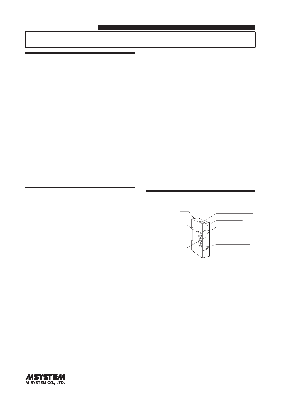
COMPONENT IDENTIFICATION
TerminalCover
PowerIndicatorLED
ConfiguratorJack
Body
Specification
OutputSettingDIPSW
InputSettingDIPSW
(side)
M5XAMS
5-2-55, Minamitsumori, Nishinari-ku, Osaka 557-0063 JAPAN
Phone: +81(6)6659-8201 Fax: +81(6)6659-8510 E-mail: info@m-system.co.jp
EM-2774 P. 2 / 4
INSTALLATION
Set the unit so that its DIN rail adapter is at the bottom.
■MOUNTING THE UNIT ON A DIN RAIL
A)Hang the upper hook at the rear side of unit on the DIN
rail.
B)Push in the lower in keeping pressing the unit to the DIN
rail.
A
B
DIN rail
■REMOVING THE UNIT
A)Pull down the DIN rail adaptor using a minus screwdriv-
er.
B)Pull out the lower part of the unit.
C)Remove the upper part from the DIN rail.
A
Slider
C
B
TERMINAL CONNECTIONS
Connect the unit as in the diagram below or refer to the connection diagram on the side of the unit.
■EXTERNAL DIMENSIONS unit: mm [inch]
94 [3.70]3 [.12]
25 [.98] 41 [1.61] (3.3 [.13])
• When mounting, no extra space is needed between units.
DIN RAIL
35mm wide
8–M3.5 SCREW
7.3 [.29]
12
34
56
78
■CONNECTION DIAGRAM
+
–
4
3
1
2
JACK
Configurator Jack
DC Current
Input (Z1)
+
–
OUTPUT
7
8
5
6
+
–
POWER
HOLD CONTROL
SWa
SWb
WIRING INSTRUCTIONS
■SCREW TERMINAL
Torque: 0.8 N·m
M5XAMS
5-2-55, Minamitsumori, Nishinari-ku, Osaka 557-0063 JAPAN
Phone: +81(6)6659-8201 Fax: +81(6)6659-8510 E-mail: info@m-system.co.jp
EM-2774 P. 3 / 4
EXTERNAL VIEWS
■LEFT VIEW ■FRONT VIEW
Output Setting
DIP SW Input Setting
DIP SW
1
2
3
4
5
6
SW1
On
Power Indicator LED
Configurator Jack
1
2
3
4SW2
On
■RIGHT VIEW
OUTPUT RANGING
The internal DIP switch setting is required to select I/O types before setting a precise I/O range using PC Configurator Soft-
ware (model: M5CFG).
For detailed information on the PC configuration, refer to the M5CFG users manual.
Table 1. DIP switch settin: Input type
Input Type SW2
1234
0 – 50 mA DC ON OFF OFF OFF
-1000 – +1000 mV DC OFF ON OFF OFF
-10 – +10 V DC OFF OFF OFF OFF
Table 2. DIP switch setting: Output type
Output Type SW1
123456
0 – 20 mA DC ON OFF OFF OFF ON OFF
-5 – +5 V DC OFF ON ON OFF OFF ON
-10 – +10 V DC OFF ON OFF ON OFF ON
CHECKING
1) Terminal wiring: Check that all cables are correctly con-
nected according to the connection diagram.
2) Check DIP switch setting.
3) Power input voltage: Check voltage across the terminal
7 – 8 with a multimeter.
4) Input: Check that the input signal is within 0 – 100% of
the full-scale. When the output does not track the input
signal, check that the terminals 3 – 4 (shortcircuited or
open) is match to the setting.
5) Output: Check that the load resistance meets the de-
scribed specifications.
POWER INDICATOR LED
The transmitter is provided with a power indicator LED
which blinks in different patterns indicating various oper-
ating status.
The following figure indicates typical patterns.
LEDONOFFPATTERNSTRANSMITTERSTATUS
Downloadingthesetting
Rangesetting
Fineadjusting
Supplyingafixedoutput
Normal
AbnormalOperation
(corruptionofconfigurationdata)
80ms
M5XAMS
5-2-55, Minamitsumori, Nishinari-ku, Osaka 557-0063 JAPAN
Phone: +81(6)6659-8201 Fax: +81(6)6659-8510 E-mail: info@m-system.co.jp
EM-2774 P. 4 / 4
MAINTENANCE
Regular calibration procedure is explained below:
■CALIBRATION
Warm up the unit for at least 10 minutes. Apply 0%, 25%,
50%, 75% and 100% input signal. Check that the output
signal for the respective input signal remains within accu-
racy described in the data sheet. When the output is out of
tolerance, recalibrate the unit using the PC Configurator
Software (model: M5CFG).
LIGHTNING SURGE PROTECTION
M-System offers a series of lightning surge protector for
protection against induced lightning surges. Please contact
M-System to choose appropriate models.