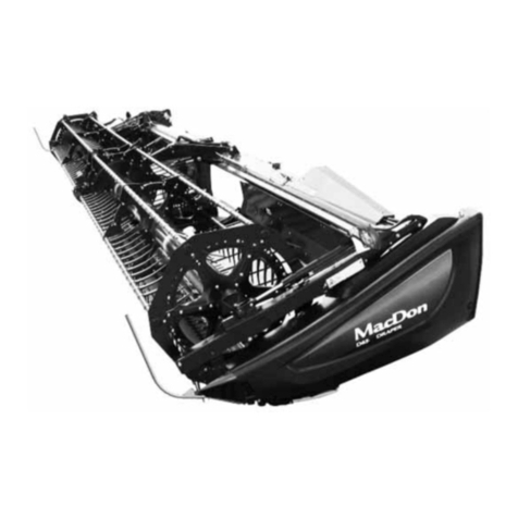
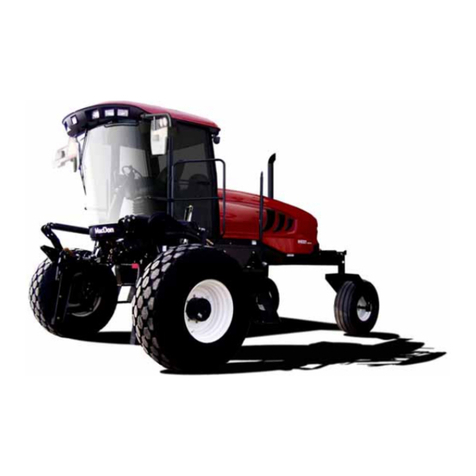
MacDon FD75 User manual

Draper Clinic Handout

Draper Clinic Handout
1
Flex
Flex vs Float –When to Lock and Unlock
Table of Contents
ØAlways Lock for Road Transport.
ØCan be Either Locked or Unlocked in the Field.
Ø2 Latches -Each Wing Locks Independently.
ØEach Wing Flexes Independently.
ØReel Flexes with Cutterbar to Maintain Close
Consistent Relationship With Knife.
ØAlways Lock for Road
Transport.
ØAlways Unlock in the Field.
Ø2 Latches to Lock/Unlock –One
on Each side of Adapter
ØWhen Properly Set, Header
Floats off of Adapter to Lightly
Follow Terrain.
Float
Refers to Flexing of the 3 Piece Header Frame
Refers to Separation (or Float) Between Adapter and Header

Break-In Service
Please Refer to Maintenance and Servicing Section of Operators Manual
Draper Clinic Handout
2
Find your operators manual at: www.macdon.com/support/operators-manuals
At 5 hours
Check knife drive belt tension (single or untimed knife)
2. Loosen the two bolts (A) that secure the motor assembly to the header end sheet (see
figure 7.103 at right).
3. Turn adjuster bolt (B) clockwise to move the drive motor until a force of 20 ft·lbf (80 N·m)
deflects the belt ¾ inches (18 mm) at mid-span.
To prolong belt life do not overtighten. Please refer to the maintenance and servicing section of your operators manual
Check knife drive belt tension (timed double knifed)
1. Open end sheet.
2. Loosen the two bolts (A) on drive belt idler bracket (see figure 7.117 at right).
3. Position pry bar under idler bracket, and push bracket upwards until a force of 6 ft·lbf (27
N·m) deflects the timing belt ½ inch (13mm) at mid-span.
4. Tighten nuts (A) on idler mounting bracket.
5. Loosen bolts (B) and adjust guide (A) shown in figure 7.118 on right. The measurement
should be 0.02-0.04 inches (0.5 –1.0 mm).
6. Readjust tension of a new belt after a short run-in period (about 5 hours).
Check for Loose Hardware
Check for loose hardware and tighten to required torque. Refer to torque specifications section of operators manual.
Check knife drive box mounting bolts
Check the four knife drive box mounting bolts (A1, A2) torque after the first 10 hours
operation and every 100 hours thereafter. Tighten knife drive box side bolts (A1) first,
then the bottom bolts (A2). Torque to 200-ft lbs (271 N m).
At 10 hours
Check Reservoir Hydraulic Fluid on Combine Adapter
Check fluid level every 25 hours with cutterbar just touching the ground. Check when oil is
cold and with center link fully retracted. At ambient temperatures above 95ºF (35ºC) it may
be necessary to lower oil level slightly to prevent overflow. CA20 and CA25 combine
adapters use 15w –40 engine oil in this reservoir. For other models please refer to your
operators manual to find the correct fluid requirements for your specific equipment.
Maintain oil level as indicated by (D) in figure 7.32
At 5 minutes
Break-In Service
Please Refer to Maintenance and Servicing Section of Operators Manual
Draper Clinic Handout
3
Find your operators manual at: www.macdon.com/support/operators-manuals
At 50 hours
Change Hydraulic Oil Filter
Change hydraulic oil filter (B) after first 50 hours of operation, and
every 250 hours thereafter.
CA20 use filter part #151975
CA25 with Bosch hydraulic block use filter part #123989
CA25 with a Parker hydraulic block use filter part #151975
Please Refer to Maintenance and Servicing Section of Operators Manual
Change oil in
header drive
gearbox using
2.6 quarts (2.5
liters) or 85W -
140 (API
service class
GL-5) Oil.
Change oil in knife
drive gearbox(s)
using 2.3 quarts (2.2
liters) of 85W -140
(API service class
GL-5) oil.
Check and Adjust Tension on Gearbox Drive Chain
The chain inside the gearbox has been tensioned at the factory and requires
no other maintenance other than to adjust the tension every 500 hours or
annually. To adjust chain tension follow these steps:
1. Lower header, stop engine, and remove key.
2. Remove chain adjusting cover (A). Be sure gasket (B) is not
damaged.
3. Remove retainer plate (C).
4. Tighten bolt (D) to 60 in lbf (6.8 N m) and then back off bolt
by 1 and 2/3 turns.
5. Reinstall retainer plate (C).
6. Reinstall chain adjusting cover (A) and gasket (B). Torque
hardware to 84 in lbf (9.5 N m).
Please Refer to Maintenance and Servicing Section of Operators Manual

Lubrication
Draper Clinic Handout
4
Find your operators manual at: www.macdon.com/support/operators-manuals
Lubricant Specification
Lubricant Specification Description Use Capacities
High Temperature Extreme Pressure (EP2) Performance With 1%
Max. Molybdenum Disulphide (NLGI Grade 2) Lithium Base
As Required Unless
Otherwise Specified
-
High Temperature Extreme Pressure (EP) Performance with 10%
Max Molybdenum Disulphide (NLGI Grade 2) Lithium Base
Driveline Slip-Joints -
Knife Drive Box 2.3 quarts (2.2 liters)
Main Drive Gearbox 5 pints (2.5 liters)
Hydraulic
Oil
SAE 15W-40
Compliant With SAE Specs For API Class SJ And CH-4 Engine Oil
Header Drive Systems
Reservoir
16 US gallons (60
liters)
Grease
SAE Multi-Purpose
Gear
Lubricant
SAE 85W-140
API Service Class GL-5
Greasing –Single Knife vs Double Knife & Flex Header vs Rigid Header
Figure 7.23 (above) –Single Knife or Untimed Double Knife Figure 7.24 (above) –Timed Double Knife Header
Figure 7.25 (above) –Adapter Figure 7.28 (above) –FD75 Flex Header

10-25 Hour Service Interval
Draper Clinic Handout
5
10 hours or daily
•Check and adjust knife hold
downs
•Hold down clearance 0.004 -
0.024in. (0.1 -0.6mm)
25 hours
•Grease knife head. 1-2 pumps
every 25 hrs. Do not over
grease.
During the break in period, center
drum drive chain (B) should be
checked periodically every 10-50
hours and adjusted as the drive
chain stretches.
Find your operators manual at: www.macdon.com/support/operators-manuals
During Break in Period
Please Refer to Maintenance and Servicing Section of Operators Manual for Model Specific Maintenance

50 Hour Service Interval
Draper Clinic Handout
6
Please Refer to Maintenance and Servicing Section of Operators Manual for Model Specific Maintenance
Find your operators manual at: www.macdon.com/support/operators-manuals
Grease Drive Roller Bearing (A), Idler Roller –Both Sides (B), Driveline Slip Joint (C), Driveline
Universal 2 PLCS (D)
On timed double knife drive headers only: grease drive shaft in header back tube every 50
hours –Refer to operators manual or greasing decal on header frame for details.

100 Hour Service Interval
Draper Clinic Handout
7
100 Hours (Chains)
•Every 100 hours or less-check and adjust
tension on rotating feed drum drive chain (A)
and reel drive chain (F). Follow procedure in
Maintenance and Service section of Operator’s
Manual to remove and replace chain covers.
Liberally apply grease to both drive chains.
Find your operators manual at: www.macdon.com/support/operators-manuals
100 Hour (Greasing)
A -Float Pivot-RH & LH
B & D -Float Spring Tensioners
(2 on each side)
C -Upper Cross Auger -if
equipped (1 Place)
E- Driveline Guard (2 Places)
100 Hours (Check Fluids)
Remove plug (B) and check oil level
in knife drive gearboxes (A).
Check oil level in main drive gearbox
at location (D).
Please Refer to Maintenance and Servicing Section of Operators Manual for Model Specific Maintenance

250 Hour Service Interval
Draper Clinic Handout
8
Grease auger pivots (A), right side wheel
axle (B), left side wheel pivot (C), and
frame wheel pivot (D). Note: Axle (B) is not
greasable on 2017 and newer transports.
Grease upper cross auger U-joint bearings (A &
B below)
Find your operators manual at: www.macdon.com/support/operators-manuals
FD75 Only
•Grease wing flex linkages (C) every 250
hours (4 places)
Grease Reel U-Joint (A)
-CA20 uses
filter part
#151975
-CA25 with
Bosch block
uses part
#123989
-CA25 with
Parker block
uses part
#151975
Change hydraulic oil filter (B) after first 50 hours
and every 250 hours thereafter.
Please Refer to Maintenance and Servicing Section of Operators Manual for Model Specific Maintenance
-Double reel only
Greaseless on 2017 & Newer

500 Hour Service Interval
Draper Clinic Handout
9
Adjust Tension on Gearbox Drive Chain
The chain inside the gearbox has been tensioned at the factory and requires
no other maintenance other than to adjust the tension every 500 hours or
annually. To adjust chain tension follow these steps:
1. Lower header, stop engine, and remove key.
2. Remove chain adjusting cover (A). Be sure gasket (B) is not
damaged.
3. Remove retainer plate (C).
4. Tighten bolt (D) to 60 in lbf (6.8 N m) and then back off bolt by
1 and 2/3 turns.
5. Reinstall retainer plate (C).
6. Reinstall chain adjusting cover (A) and gasket (B). Torque
hardware to 84 in lbf (9.5 N m).
Find your operators manual at: www.macdon.com/support/operators-manuals
Grease
A- Reel Shaft RH bearing (1 Place)
B- Reel Center Bearing (1 Place)
C- Wheel Bearings (4 Places)
D- Reel Shaft LH Bearing (1 Place)
Please Refer to Maintenance and Servicing Section of Operators Manual for Model Specific Maintenance

1000 Hour or 3 Year Service Interval
Draper Clinic Handout
10
Change oil in header drive gearbox
using 2.6 quarts (2.5 liters) or 85W-
140 (API service class GL-5) Oil.
Find your operators manual at: www.macdon.com/support/operators-manuals
Change oil in knife drive gearbox(s)
using 2.3 quarts (2.2 liters) of 85W-
140 (API service class GL-5) oil.
Change hydraulic oil in combine
adapter frame using 16 US gallons
(60 liters) of 15W –40 engine oil.
CAUTION: Never use gasoline, naphtha or any volatile material for cleaning purposes. These materials may be toxic
and/or flammable.
CAUTION: Cover cutterbar and knife guards to prevent injury from accidental contact.
1. Clean the header thoroughly.
2. Store the machine in a dry, protected place if possible. If stored outside, always cover with waterproof canvas or other protective material.
3. If machine is stored outside, remove drapers and store in a dark, dry place.
NOTE: If drapers are not removed, store header with cutterbar lowered so water/snow will not accumulate on drapers. This
accumulation of weight puts excessive stress on drapers and header.
4. Lower header onto blocks to keep cutterbar off the ground.
5. Lower reel completely. If stored outside, tie reel to frame to prevent rotation caused by wind.
6. Repaint all worn or chipped painted surfaces to prevent rust.
7. Loosen drive belts.
8. Lubricate the header thoroughly, leaving excess grease on fittings to keep moisture out of bearings. Apply grease to exposed threads,
cylinder rods, and sliding surfaces of components. Oil knife components to prevent rust.
9. Check for worn or broken components and repair or order replacement from your MacDon Dealer. Attention to these items right away will
save time and effort at the beginning of next season.
10. Replace or tighten any missing or loose hardware.
End of Season Service
Please Refer to Maintenance and Servicing Section of Operators Manual for Model Specific Maintenance

Adjusting Reel Cam Angle Positions
Draper Clinic Handout
11
Please Refer to Maintenance and Servicing Section of Operators Manual
Find your operators manual at: www.macdon.com/support/operators-manuals
Adjusting Deck Height
•Release Draper tension, remove tube connectors,
lift up at front edge past cutterbar and roll back.
•Measure draper belt thickness.
•Adjust deck height (A in Fig 10.12) to be 1 mm
greater than belt thickness.
Adjusting Draper Deck Height
D and FD series headers feature a 4 position reel cam adjustment
on the right end each reel (split reel headers must be adjusted
separately for each reel). The factory cam setting is position 2. Use
a ¾” (19mm) wrench to rotate pin and adjust cam to a different
position. Please Refer to Maintenance and Servicing Section of Operators Manual
Cam position 4: Most
aggressive position, use in
lodged crops or w hen reel
fore/aft is extended with the
reel ahead of the knife.
Cam position 1: Most
gentle position, use in
shatter prone crops or
when reel fore/aft is
retracted behind knife.

Knife Maintenance
Draper Clinic Handout
12
Find your operators manual at: www.macdon.com/support/operators-manuals
Knife Hold Down Adjustment
•Check hold downs every 10 hrs or daily.
•Hold down clearance 0.004 -0.024in. (0.1 -0.6mm)
Double Knife Center Guard Adjustment
•Check clearance periodically.
•If required (crop stripping) adjust clearance to
0.004-0.016 in. (0.1-0.4mm) at guide tip 0.004-
0.040 in. (0.1-0.4mm) at rear of guide.
•Torque nu t s (B) t o 53f t -lbs.
Adjusting Feed Draper Tension
•Check that Draper is engaged properly in groove
of drive roller.
•Hold nut (B) with wrench and turn bolt (C)
clockwise to increase tension and
counterclockwise to decrease tension.
•Adjust both sides equally.
•Correct tension is when retainer (D) is flush with
spring holder, and bolt (E) is free.
•Tension shoul d be just enough to prevent s l ipping
and keep draper from sagging below cutterbar.
Please Refer to Maintenance and Servicing Section of Operators Manual
Adjusting Center Feed Draper Tension

Adjusting Side Draper Tension
Draper Clinic Handout
13
Adjusting Side Draper Tension
•Turn bolt (A) clockwise and white indicator bar (B)
will move inward, indicating that the draper is
being tightened.
•Turn bolt (A) counterclockwise and indicator bar
(B) will out outboard, indicating the draper is being
loosened.
•When properly tensioned, the white indicator (B)
will be halfway across the inboard side as shown.
•Please Refer to Maintenance and Servicing Section of Operators Manual
Find your operators manual at: www.macdon.com/support/operators-manuals
(7)-Sickle Guard—Center,
Pointed Part Number 124338
(8) -Pointed Guide–Top-Center,
Part Number 124344
(9) -Bar -Adjuster Part 34980
(D) -Nut -Part number 18654
(E)-Bolt -Part Number 50120
(F)-Bolt -Part Number 132404
Center Guard parts -Double Knife Drive Headers
Pointed Guard Part Numbers for D and FD Headers
Standard (non stub) guards used in most locations across
cutterbar. Part #118344
The next 3 guards inboard from either knife drive gear box are
Part #118345 which have no back ledger and allow the knife
freedom to oscillate. Double knife headers have 6, single
knife have 3.
Both single and double knife D and FD headers have a half guard at each end of the
header. LH half guard is a Part # 118301 and RH half guard is Part # 118302 (standard
non stub guards).
Please Refer to the MacDon parts catalogue for part numbers on your specific model

Draper Clinic Handout
14
Setting Auto Header Height Control
3. Unlock float handles
(below) on each side of
combine adapter. Up is
locked, down is unlocked.
4. With stabilizer wheels fully raised and header resting on
ground, slightly raise and lower combine feeder house while
monitoring the float indicator (A) to verify that indicator has full
range from 0 –4 and that needle doesn’t stick.
1. Ensure that header float is properly adjusted. Reference the float adjustment section or watch float and
wing balance video series at http://www.macdon.com/videos
2. Perform a header calibration on your combine (refer to operators manual). In some cases the voltage
range will need to be adjusted on the float indicator potentiometer before the combine will calibrate. If
required, then please refer to your header operators manual for this adjustment procedure.
5. Adjust feeder house height until float needle indicates position 2. This is the recommended ground
pressure start point. In wet conditions this may need to be lighter (i.e.1.5)
6. Save float indicator position 2 on your combines auto header height control.
7. With combine parked and header completely lowered, increase combines auto header height control
sensitivity until combine feeder house begins to “hunt” or to automatically raise and lower with the combine
parked stationary. Slightly decrease sensitivity until feeder house stops “hunting”.
8. When cutting on the ground, float should range from 1-3 on indicator (A) above, with the auto header
height control correcting the needle back to position 2 reasonably quickly. When cutting on the ground, it is
important that AHHC maintain a range from 0.5-3 on the float indicator since this will keep float springs
properly tensioned resulting in correct header ground pressure the best terrain following performance. When
cutting off the ground using AHHC (see page 15) needle might be set to position 1 and range from 0-2.
Header Float (A)
Header Tilt (B)
MacDon auto header height control (AHHC) functions by sensing the
separation (or float) between the header and the combine adapter.
The header senses and follows the terrain by riding lightly along the
ground suspended from the combine adapter under spring tension. If
the header floats up or down off of the combine adapter following the
terrain, then AHHC will sense this and will adjust the feeder house
and combine adapter to follow the header either up or down.
Setting Auto Header Height Control:

Draper Clinic Handout
15
Stabilizer Wheel Operation
Adjusting Slow Speed Transport Latch
If slow speed transport latch is difficult to engage (A in
figure 4.100), then adjust wheel hang height on rear axel
by loosening jam nut and turning bolt at rear axel swing
joint using a ¾” or 19mm wrench and socket (see E and
D in figure 3.46 below). Retighten jam nut after adjusting.
•Please Refer to Maintenance and Servicing Section of Operators Manual
***Important: There should only be one point of contact with the ground
at any time, either the cutterbar, skid shoes or stabilizer wheels****
When cutting on the ground: All stabilizer wheels should be locked into the
highest notch with wheels completely off the ground.
When cutting off the ground:
ØHeaders equipped with stabilizer wheel slow speed transport:
Wheels should be adjusted so that the spring is compressed to between 2 and 3 on
the stabilizer wheel compression gauge (see figure 1). Depending on header
configuration, it might be necessary to adjust LH and RH wheels to different notches
to achieve this proper compression and level cut height.
ØHeaders equipped with the stabilizer wheels only (non transport):
Operate with springs compressed as shown in figure 2. Total spring compression
should be 11.6 –13.6 inches (295-345 mm). It might be necessary to adjust LH and
RH wheels to different notches to achieve proper compression and level cut height.
Auto header height control when cutting off the ground: To operate with
AHHC when cutting off the ground, it might be necessary to lighten float or to add
slightly more compression to stabilizer wheel springs so that the header will float
upward off of adapter to sense terrain. Ensure that float is unlocked and properly
adjusted (see page 20), do not over compress springs as this may result in hazard or
damage to the shock and spring assembly. See page 14 for setting of AHHC.
Figure 2
Figure 1

Draper Clinic Handout
16
Upgrades for your FlexDraper
Benefits:
1) A more positive connection between the adapter & the header.
2) Greatly reduces the chances of feed deck damage.
3) Upgrades to FD75 specs.
New Connection Link
Fits: 2011 & prior FD70
Kit #: Part #123719
Service Bulletin #: 1115_A
Some welding is required.
Old Chain Links
New Draper Deck Front Hinge Joint
Fits: All FD70's
Kit #: Part #220196
Service Bulletin #: 1249_A
Old Draper Deck Front Joint (Spring Steel)
This kit contains enough pieces to do both sides.
Some cutting and welding is required.
Benefits:
1) Longer wear life.
2) Reduces chance of damage to draper belts.
Front Link Upgrade Kit
Front Track Hinge Kit
New Ball Joint System
Fits: All FD70's
Kit #: Part #245810
Service Bulletin #: 1530_A
Old/Worn Bushing System
This kit contains enough pieces to do both sides.
Compression Link Upgrade Kit
Benefits:
1) Eliminates rubber bushing
2) More consistent wing balance

Draper Clinic Handout
17
Benefits:
1) More uptime & more convenience.
2) Reverse the knife from the operators seat.
3) No need to leave the cab to clear the knife in most
instances.
4) Upgrades to FD75 specs.
Knife Reverser Block
Fits: All FD70’s
Kit #: Whole Goods #B4962
Service Bulletin #: N/A
Upgrades for your FlexDraper
Knife Reversing Kit
Benefits:
1) Upgrades to FD75 Specs.
2) Seals front corners of adapter to header. Improved
sealing means more of your seed is saved while still
retaining the front rock sump.
Fits: All FD70's (Factory installed on all FD75’s)
Kit #: Part #279028 Kit
Drilling is required on some models.
Seed Saver Kit
Benefits:
Seals adapter to header. Improved
sealing means more of your seed is
saved while still retaining the front
rock sump.
Fits: All FD70's & FD75's
Kit #: For FD70 -Whole Goods #B5661 (Includes items in seed saver kit above)
For FD75 -Whole Goods #B5612
Service Bulletin #: N/A
Delicate Seed Kit Kit does not generally improve performance in
most cereal or large seed pulse crops.

Draper Clinic Handout
18
Benefits:
1) Improves performance with less carry-over & wrapping.
2) Increased clearance between reel and header end sheets
3) Increased strength.
4) Upgrades to FD75 specs.
Fits: All FD70's
Kit #: See Chart
Service Bulletin #: 1518_A
5 Bat Reel:
Part #Description Quantity
164958 Support -Endshield Reel 15
164754 Endshield -5 bat segmented 5 Series 15
135157 Screw -Machine 15
30228 Nut -Flange DT smooth face 0.375-16Unc 15
105136 Screw -Machine 15*
50186 Nut -Flange lock SM face DT 0.500-13Unc gr5 15*
*Hardware is attached to the reel.
Benefits:
1) Improved Crop Flow & Productivity.
2) Resistance to Corrosion.
3) Improved Durability.
4) It just looks good.
5) Upgrades to FD75 Specs.
Fits: 2013 FD75's & All FD70's
Kit #: Whole Goods #B5819
Service Bulletin #: N/A
Redesigned Reel End Shields
Upgrades for your FlexDraper
Stainless Steel Feed Pan
Stubble Light Kit
Benefits:
1) Improved night visibility.
2) Less operator fatigue.
3) Better harvesting results.
Fits: FD75 on JD Combines Only
Kit #: Whole Goods #B6140
Service Bulletin #: N/A
Benefits:
1) Extended fill tube option for hydraulic reservoir.
2) Allows reservoir to be fully filled for working in
extreme hills.
3) Prevents pump cavitation's at extreme angles.
4) Recommended when header is used on a combine
equipped with leveling system (Hilco, etc.)
Fits: FD75 & All FD70's
Kit #: Whole Goods #B6057
Service Bulletin #: N/A
Fill Tube Extension Kit

Straight Cut Canola Optimization
Draper Clinic Handout
19
Optimize Reel Cam Position for Canola
•In standing shatter prone canola, the reel should be retracted as far
back (Aft) as possible to contain shatter loss onto the draper table.
Reel cam positions should also be adjusted to release crop and
prevent carry around. Reel cam positions are adjusted on the right
end of each reel. Please see page 11 of this document for further
information on reel cam positions and how to adjust them.
Optimize Header Tilt for Canola
•Retracting header tilt angle to position “A” or “B” will extend
the feed drum further into the crop and may aid crop
feeding in some high volume crop conditions.
Optimize Cross Auger, Reel & Side Drapers for Canola
•Leave Center Beaters on UCA. In these ripe fluffy conditions
they aid in crop delivery into Feed Auger.
•Reel Position
•As far rearward (Aft) as possible, delivering crop flow
into UCA, ensuring reel is behind C-bar.
•Reel height so that fingers just engage the crop. If reel is
too low it can hamper crop flow.
•Reel Cam set to position 1.
•Speed equal to ground speed.
•Side Draper Speed
•Full Open on CA20
•Position 9 on CA25
Find your operators manual at: www.macdon.com/support/operators-manuals
Other manuals for FD75
5
Table of contents
Other MacDon Farm Equipment manuals

MacDon
MacDon DWA Guide

MacDon
MacDon M155E4 User manual

MacDon
MacDon FlexDraper FD2 Series User manual

MacDon
MacDon R216 Parts list manual

MacDon
MacDon A30-S User manual

MacDon
MacDon R113 User manual

MacDon
MacDon R216 User manual

MacDon
MacDon M155 User manual

MacDon
MacDon R216 User manual

MacDon
MacDon D50 User manual
Popular Farm Equipment manuals by other brands

Euro Systems
Euro Systems P130 Translation of the original

Omlet
Omlet Eglu Go 2m Run instruction manual

Hedensted Gruppen
Hedensted Gruppen HG FEEDER 600 user manual

Krone
Krone MX 310 GL Original operating instructions

SKY Agriculture
SKY Agriculture 20 Series Original instructions

AGROWPLOW
AGROWPLOW Agrowseeder AD082 Operator's manual