MacDon M150 User manual

Form # 169018 Model Year - 2009
M150, M200 Self-Propelled Windrower
UNLOADING & ASSEMBLY
INSTRUCTIONS
for
NORTH AMERICAN SHIPMENTS

Form # 169018 Model Year - 2009
MACDON SELF PROPELLED AUGER HEADER
MACDON SELF PROPELLED WINDROWER TRACTOR

Form # 169018 Model Year - 2009
1
INTRODUCTION
This instruction describes the unloading, set-up and pre-delivery requirements for the MacDon M Series Self-
Propelled M150 and M200 Windrower Tractors. Use the table of contents to guide you to specific areas.
Retain this instruction for future reference.
CAREFULLY READ ALL THE MATERIAL PROVIDED BEFORE ATTEMPTING TO UNLOAD, ASSEMBLE,
OR USE THE MACHINE.
TABLE OF CONTENTS
INTRODUCTION........................................................................................................................................................1
GENERAL SAFETY...................................................................................................................................................2
RECOMMENDED TORQUES ...................................................................................................................................4
A. GENERAL..................................................................................................................................................4
B. SAE BOLTS...............................................................................................................................................4
C. METRIC BOLTS ........................................................................................................................................4
D. HYDRAULIC FITTINGS.............................................................................................................................5
ACCRONYMS AND ABBREVIATIONS .....................................................................................................................6
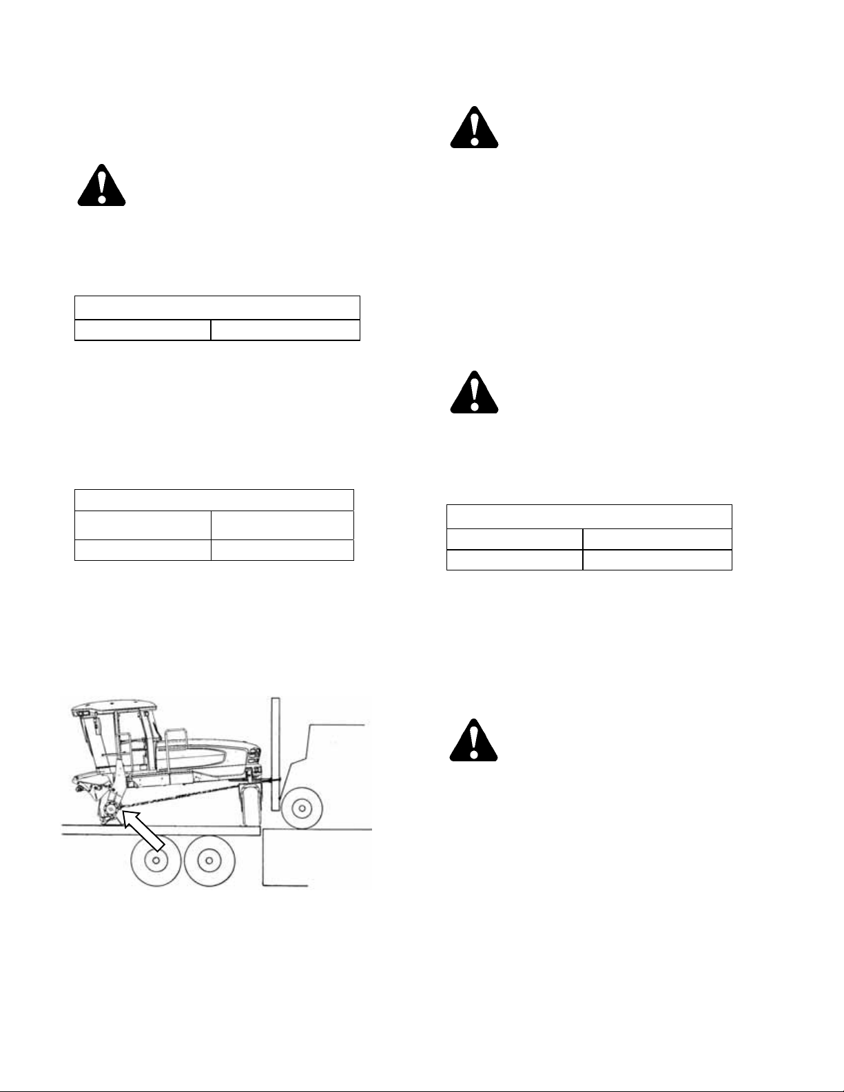
STEP 1. UNLOAD TRACTOR...........................................................................................................................7
A. TWO FORKLIFT METHOD .......................................................................................................................7
B. SINGLE FORKLIFT METHOD ..................................................................................................................8
METHOD 1........................................................................................................................................................................ 8
METHOD 2........................................................................................................................................................................ 8
STEP 2. REPOSITION RH LEG......................................................................................................................10
STEP 3. INSTALL FRONT WHEELS ..............................................................................................................11
STEP 4. REPOSITION CASTER WHEELS ....................................................................................................11
STEP 5. INSTALL STEPS ...............................................................................................................................12
STEP 6. INSTALL CENTER LINK...................................................................................................................13
STEP 7. INSTALL BATTERIES (2) .................................................................................................................13
STEP 8. INSTALL AM/FM RADIO...................................................................................................................14
STEP 9. ATTACH HEADER............................................................................................................................16
I. HEADER ATTACHMENT - D SERIES.............................................................................................................. 16
II. HEADER ATTACHMENT – A SERIES ............................................................................................................. 20
III. HEADER ATTACHMENT – R SERIES ............................................................................................................. 23
STEP 10. LUBRICATE MACHINE.....................................................................................................................27
STEP 11. PROGRAM CDM...............................................................................................................................29
STEP 12. PERFORM PRE-DELIVERY CHECKS.............................................................................................35
A. FINAL DRIVE LUBRICANT LEVEL.........................................................................................................35
B. TIRE PRESSURES .................................................................................................................................35
C. ENGINE COOLANT.................................................................................................................................35
D. AIR CLEANER.........................................................................................................................................35
E. HYDRAULIC OIL LEVEL.........................................................................................................................36
F. FUEL SEPARATOR ................................................................................................................................36
G. GEAR BOX LUBRICANT LEVEL ............................................................................................................37
H. A/C COMPRESSOR BELT......................................................................................................................37
I. PERFORM SAFETY SYSTEM CHECKS................................................................................................37
J. OPERATIONAL CHECKS .......................................................................................................................39
I. ENGINE WARNING LIGHTS ............................................................................................................................ 39
II. START ENGINE................................................................................................................................................ 39
III. GAUGES AND CDM DISPLAY......................................................................................................................... 40
IV. ENGINE SPEED ............................................................................................................................................... 40
V. OPERATOR’S PRESENCE SYSTEM CHECKS...............................................................................................41
VI. EXTERIOR LIGHTS.......................................................................................................................................... 42
VII. INTERIOR LIGHTS........................................................................................................................................... 43
VIII. A/C AND HEATER............................................................................................................................................ 43
K. MANUALS ...............................................................................................................................................43
L. CAB INTERIOR .......................................................................................................................................43

Form # 169018 Model Year - 2009
2
GENERAL SAFETY
CAUTION
The following are general farm safety
precautions that should be part of your
operating procedure for all types of
machinery.
•Protect yourself.
•When assembling, operating and
servicing machinery, wear all the
protective clothing and personal safety
devices that COULD be necessary for the
job at hand. Don't take chances.
•You may need:
oa hard hat.
oprotective shoes with slip resistant
soles.
oprotective glasses or goggles.
oheavy gloves.
owet weather gear.
orespirator or filter mask.
ohearing protection. Be aware that
prolonged exposure to loud noise
can cause impairment or loss of
hearing. Wearing a suitable hearing
protective device such as ear muffs
(A) or ear plugs (B) protects against
objectionable or loud noises.
•Provide a first-aid kit for use in case of
emergencies.
•Keep a fire extinguisher on the machine.
Be sure the extinguisher is properly
maintained and be familiar with its proper
use.
•Keep young children away from
machinery at all times.
•Be aware that accidents often happen
when the operator is tired or in a hurry to
get finished. Take the time to consider
the safest way. Never ignore warning
signs of fatigue.
•Wear close-fitting
clothing and cover long
hair. Never wear
dangling items such as
scarves or bracelets.
•Keep hands, feet,
clothing and hair away
from moving parts.
Never attempt to clear
obstructions or objects from a machine
while the engine is running.
•Keep all shields in place. Never alter or
remove safety equipment. Make sure
driveline guards can rotate
independently of the shaft and can
telescope freely.
•Use only service and repair parts made
or approved by the equipment
manufacturer. Substituted parts may not
meet strength, design, or safety
requirements.
•Do not modify the machine. Unauthorized
modifications may impair the function
and/or safety and affect machine life.
A
B

Form # 169018 Model Year - 2009
3
•Stop engine and remove key from
ignition before leaving operator's seat for
any reason. A child or even a pet could
engage an idling machine.
•Keep the area used for servicing
machinery clean and dry. Wet or oily
floors are slippery. Wet spots can be
dangerous when working with electrical
equipment. Be sure all electrical outlets
and tools are properly grounded.
•Use adequate light for the job at hand.
•Keep machinery clean. Do not allow oil or
grease to accumulate on service
platforms, ladders or controls. Clean
machines before storage.
•Never use gasoline, naphtha or any
volatile material for cleaning purposes.
These materials may be toxic and/or
flammable.
•When storing machinery, cover sharp or
extending components to prevent injury
from accidental contact.

Form # 169018 Model Year - 2009
4
RECOMMENDED TORQUES
A. GENERAL
The tables shown below give correct torque
values for various bolts and capscrews.
•Tighten all bolts to the torques specified in
chart unless otherwise noted throughout this
manual.
•Check tightness of bolts periodically, using
bolt torque chart as a guide.
•Replace hardware with the same strength
bolt.
•Torque figures are valid for non-greased or
non-oiled threads and heads unless
otherwise specified. Do not grease or oil
bolts or capscrews unless specified in this
manual. When using locking elements,
increase torque values by 5%.
B. SAE BOLTS
NC BOLT TORQUE*
SAE 5 SAE 8
BOLT
DIA. "A"
in. ft·lbf N·m ft·lbf N·m
1/4 9 12 11 15
5/16 18 24 25 34
3/8 32 43 41
56
7/16 50 68 70 95
1/2 75 102 105 142
9/16 110 149 149 202
5/8 150 203 200 271
3/4 265 359 365 495
7/8 420 569 600 813
1 640 867 890 1205
* Torque categories for bolts and capscrews are identified by their
head markings.
C. METRIC BOLTS
NC BOLT TORQUE*
8.8 10.9
BOLT
DIA. "A"
ft·lbf N·m ft·lbf N·m
M3 0.4 0.5 1.3 1.8
M4 2.2 3 3.3 4.5
M5 4 6 7 9
M6 7 10 11 15
M8 18 25 26 35
M10 37 50 52 70
M12 66 90 92 125
M14 103 140 148 200
M16 166 225 229 310
M20 321 435 450 610
M24 553 750 774 1050
M30 1103 1495 1550 2100
M36 1917 2600 2710 3675
* Torque categories for bolts and capscrews are identified by their
head markings.
8.8 10.9
SAE-5 SAE-8

Form # 169018 Model Year - 2009
5
D. HYDRAULIC FITTINGS
FLARE TYPE
a. Check flare and flare seat for defects that might
cause leakage.
b. Align tube with fitting before tightening.
c. Lubricate connection and hand tighten swivel
nut until snug.
d. To prevent twisting the tube(s), use two
wrenches. Place one wrench on the connector
body and with the second tighten the swivel nut
to the torque shown.
TORQUE
VALUE*
RECOMMENDED
TURNS TO
TIGHTEN
(AFTER FINGER
TIGHTENING)
TUBE
SIZE
O.D.
(in.)
NUT
SIZE
ACROSS
FLATS
(in.) lbf·ft N·m Flats Turns
3/16 7/16 6 8 1 1/6
1/4 9/16 9 12 1 1/6
5/16 5/8 12 16 1 1/6
3/8 11/16 18 24 1 1/6
1/2 7/8 34 46 1 1/6
5/8 1 46 62 1 1/6
3/4 1-1/4 75 102 3/4 1/8
7/8 1-3/8 90 122 3/4 1/8
* The torque values shown are based on lubricated connections
as in reassembly.
O-RING TYPE
a. Inspect O-ring and seat for dirt or obvious
defects.
b. On angle fittings, back off the lock nut until
washer (A) bottoms out at top of groove (B) in
fitting.
c. Hand tighten fitting until back up washer (A) or
washer face (if straight fitting) bottoms on part
face (C) and O-ring is seated.
d. Position angle fittings by unscrewing no more
than one turn.
e. Tighten straight fittings to torque shown.
f. Tighten angle fittings to torque shown in the
following table while holding body of fitting with a
wrench.
TORQUE
VALUE*
RECOMMENDED
TURNS TO
TIGHTEN (AFTER
FINGER
TIGHTENING)
THD
SIZE
(in.)
NUT SIZE
ACROSS
FLATS
(in.)
lbf·ft N·m Flats Turns
3/8 1/2 6 8 2 1/3
7/16 9/16 9 12 2 1/3
1/2 5/8 12 16 2 1/3
9/16 11/16 18 24 2 1/3
3/4 7/8 34 46 2 1/3
7/8 1 46 62 1-1/2 1/4
1-1/16 1-1/4 75 102 1 1/6
1-3/16 1-3/8 90 122 1 1/6
1-5/16 1-1/2 105 142 3/4 1/8
1-5/8 1-7/8 140 190 3/4 1/8
1-7/8 2-1/8 160 217 1/2 1/12
* The torque values shown are based on lubricated connections
as in reassembly.
FLARE
FLARESEAT BODY
NUT
LOCKNUT
SEAT
WASHER
O-RING
GROOVE
FITTING
A
BC

Form # 169018 Model Year - 2009
6
ACCRONYMS AND
ABBREVIATIONS
ENGLISH/METRIC EQUIVALENTS
ENGLISH FACTOR SI UNITS (METRIC)
acres x 0.4047 = hectares (ha)
ft/min x 0.3048 = meters/min (m/min)
ft/s x 0.3048 = meters/sec (m/s)
US gal x 3.7854 = liters (L)
US
gal/min
(gpm)
x 3.7854 = liters/min (L/min)
hp x 0.7457 = kilowatts (kW)
in.3x 16.3871
= cubic centimeters (cm3
or cc)
lbf x 4.4482 = newtons (N)
lbf·ft or
ft·lbf x 1.3558 = newton meters (N·m)
lbf·in. or
in·lbf x 0.1129 = newton meters (N·m)
mph x 1.6063 = kilometers/hour (km/h)
oz. x 29.5735 = milliliters (ml)
psi x 6.8948 = kilopascals (kPa)
psi x .00689 = megapascals (MPa).
DEFINITIONS
TERM DEFINITION
API American Petroleum Institute
ASTM American Society Of Testing And
Materials
C Celsius
Cab
Forward
Windrower operation with the
operator and cab facing in the
direction of travel.
CDM Cab Display Module
DWA Double Windrow Attachment
Engine
Forward
Windrower operation with the
operator and engine facing in the
direction of travel.
F Fahrenheit
ft/min feet per minute
ft/s feet per second
gpm U.S. gallons per minute
GSL Ground Speed Lever
hp horsepower
in.3cubic inches
lbf pounds force
lbf·ft or ft·lbf pound feet or foot pounds
lbf·in. or
in·lbf pound inches or inch pounds
ISC Integrated Speed Control
mph miles per hour
N-DETENT The slot opposite the neutral
position on operator’s console.
oz. ounces
psi pounds per square inch
rpm revolutions rer minute
SAE Society Of Automotive Engineers
WCM Windrower Control Module
Windrower Windrower Tractor with header
attached.
Windrower
Tractor
Power unit only. (Windrower
without the header attached).

UNLOADING AND ASSEMBLY
Form # 169018 Model Year - 2009
7
STEP 1. UNLOAD TRACTOR
CAUTION
To avoid injury to bystanders from being
struck by machinery, do not allow persons to
stand in unloading area.
A. TWO FORKLIFT METHOD
CAUTION
Equipment used for unloading must meet or
exceed the requirements specified below.
Using inadequate equipment may result in
chain breakage, vehicle tipping or machine
damage.
LIFTING VEHICLE
Min. Lifting Capacity * 5500 lb (2500 kg)
Min. Fork Length 78 in. (1981 mm)
* At 48 inches (1220 mm) from back end of
forks.
IMPORTANT
Forklifts are normally rated for a load
located 24 inches (610 mm) ahead of
back end of the forks. To obtain the
forklift capacity at 48 inches (1220
mm), check with your forklift
distributor.
a. Move trailer into position and block trailer
wheels.
b. Set forklift tines to the widest possible setting.
c. Position one forklift on either side of trailer and
position forks under windrower tractor frame.
NOTE
Windrower center of gravity is
approximately 55 inches (1397 mm)
rearward of drive wheel center.
d. Lift with both forklifts simultaneously until
windrower is clear of trailer bed.
WARNING
Be sure forks are secure before moving
trailer away from load. Stand clear when
lifting.
e. Drive the truck slowly forward until trailer bed is
clear of windrower tractor.
f. Lower unit slowly and simultaneously with both
forklifts to the ground. Place wooden blocks
under front shipping stands if ground is soft.
g. Back off forklifts.
h. Check windrower tractor for shipping damage
and check shipment for missing parts.

UNLOADING AND ASSEMBLY
Form # 169018 Model Year - 2009
8
B. SINGLE FORKLIFT METHOD
METHOD 1
CAUTION
Equipment used for unloading must meet or
exceed the requirements specified below.
Using inadequate equipment may result in
chain breakage, vehicle tipping or machine
damage.
LIFTING VEHICLE
Min. Lifting Capacity * 5500 lb (2500 kg)
* At 48 inches (1220 mm) from back end of forks.
IMPORTANT
Forklifts are normally rated for a load
located 24 inches (610 mm) ahead of
back end of the forks. To obtain the
forklift capacity at 48 inches (1220
mm), check with your forklift
distributor.
CHAIN
Type Overhead Lifting
Quality (1/2 inch)
Min. Working Load 5000 lb (2270 kg)
a. Position rear of trailer against unloading dock
that is the same height or slightly lower than the
trailer bed.
b. Remove shipped parts from under windrower
tractor frame.
c. Set forklift tines to widest possible setting.
d. Position forklift up to rear of windrower tractor
and place forks under the rear frame cross
member.
e. Install chains from forklift mast to jacking
brackets on both front legs of windrower tractor.
f. Chains must be the same length.
CAUTION
The front legs rest on the trailer bed on skid
shoes. Ensure there are no obstructions to
prevent rearward sliding of the skid shoes
and watch carefully that as unit is dragged,
the skid shoes are not sliding sideways
towards the edge of the trailer bed.
g. Drag windrower rearward off of carrier.
h. Remove chains and back off the forklift.
i. Check windrower tractor for shipping damage
and check shipment for missing parts.
METHOD 2
CAUTION
Equipment used for unloading must meet or
exceed the requirements specified below.
Using inadequate equipment may result in
chain breakage, vehicle tipping or machine
damage.
LIFTING VEHICLE
Min. Lifting Capacity * 11000 lb (4994 kg)
Min. Fork Length 78 in. (1981 mm)
* At 48 in. (1220 mm) from back end of forks.
IMPORTANT
Forklifts are normally rated for a load
located 24 inches (610 mm) ahead of
back end of the forks. To obtain the
forklift capacity at 48 inches (1220
mm), check with your forklift
distributor.
WARNING
Be sure forks are secure before moving away
from load. Stand clear when lifting.
a. Move trailer into position and block trailer
wheels.
b. Set forklift tines to the widest possible setting.
(continued next page)

UNLOADING AND ASSEMBLY
Form # 169018 Model Year - 2009
9
c. Position forklift on left or right side of trailer and
position forks under windrower tractor frame.
NOTE
Windrower center of gravity is
approximately 55 inches (1397 mm)
rearward of drive wheel center.
WARNING
Ensure forks project beyond far side of
frame.
d. Lift until windrower is clear of trailer bed.
e. Slowly back forklift away from trailer until
windrower tractor is clear of trailer.
f. Lower unit slowly to the ground. Place wooden
blocks under front shipping stands if ground is
soft.
g. Back off forklift.
h. Check windrower tractor for shipping damage
and check shipment for missing parts.

UNLOADING AND ASSEMBLY
Form # 169018 Model Year - 2009
10
STEP 2. REPOSITION RH LEG
Only the right cab-forward leg requires
repositioning from shipping to field configuration.
a. Support the front of the tractor leg off the ground
with stand (or equivalent).
b. Position jack under RH leg and raise jack slightly
to take some weight off leg.
c. Remove two bolts, washers, and nuts from
frame.
d. Tap out the two pins with a hammer.
e. Move leg out to expose one hole.
f. Re-install pins and secure with bolts, washers,
and nuts (not shown). Torque nuts to 100 ft·lbf
(136 N·m).
g. Remove bolt and shipping skids from legs.

UNLOADING AND ASSEMBLY
Form # 169018 Model Year - 2009
11
STEP 3. INSTALL FRONT
WHEELS
a. Position wheel against hub so that that air
valves are on outside and tire tread point
forward. For "Turf” tires (diamond tread), be
sure arrow on sidewall points in forward rotation.
b. Lift wheel on hub with a forklift or equivalent.
Lower forklift.
c. Rotate wheel to align holes with studs and push
wheel onto studs.
d. Install wheel nuts and tighten to 175-200 ft·lbf
(237-271 N·m) using the tightening sequence as
shown.
NOTE
To avoid damage to wheel disks, do not
over-tighten wheel nuts.
e. Repeat sequence three times.
STEP 4. REPOSITION CASTER
WHEELS
a. Raise rear of tractor slightly so that most of the
weight is off the casters, using a jack or other
lifting device under the frame where shown.
NOTE
Lifting device should have a lifting
capacity of at least 5000 lb (2270 kg).
b. Remove six bolts (four on backside, two on
underside) and washers from left and right side
of walking beam.
c. Slide extensions outboard equal amounts and
align holes at desired location.
NOTE
Illustration shows widest tread width.
IMPORTANT
Caster wheels must be equidistant
from center of tractor.
(continued next page)
1
5
3
7
8
2
4
6
LIFT HERE

UNLOADING AND ASSEMBLY
Form # 169018 Model Year - 2009
12
d. Position bracket (A) and install bolts. The two
shorter bolts (B) are installed at the back inboard
locations. Torque as follows:
1. Snug bottom bolts.
2. Tighten and torque back bolts to 330 ft·lbf
(447 Nm).
3. Tighten and torque bottom bolts to 330 ft·lbf
(447 Nm).
e. Lower tractor to ground.
IMPORTANT
f. Retorque bolts after first 5 and 10 hours of
operation.
STEP 5. INSTALL STEPS
a. Install two ½ in.x1.0 hex bolts in upper holes in
platform. Do not thread in fully.
b. Hang step assembly (both step assemblies are
the same) on bolts.
c. Install two ½ in.x1.0 lg. hex bolts in lower holes
in step and tighten.
d. Tighten upper bolts installed in step a.
e. Repeat for other step assembly.
B A

UNLOADING AND ASSEMBLY
Form # 169018 Model Year - 2009
13
STEP 6. INSTALL CENTER LINK
MECHANICAL LINK – M150 ONLY
a. Remove clevis pin from center link.
b. Position link between mounting brackets on front
frame and attach at lower hole location.
c. Install clevis pin and secure with hair pin.
HYDRAULIC LINK – M200 STD, M150 OPTION
The hydraulic center link is supplied in a
separate kit that is included with the shipment.
Refer to installation instructions in the kit.
STEP 7. INSTALL BATTERIES (2)
a. Open right hand (cab forward) maintenance
platform.
b. Remove cable ties securing battery clamps and
cables to frame.
RATING GROUP CCA VOLT MAX. DIMENSION
Heavy Duty,
Off-Road,
Vibration
Resistant
BCI 29H or
31A 750 12 13.25x7.37x9.44 in.
(337x188x240 mm)
c. Position new batteries on holder (A).
d. Install clamp (B) with bolts (C) provided and
tighten securely.
IMPORTANT
BATTERY IS NEGATIVE
GROUNDED. Always connect starter
cable to the positive (+) terminal of
battery and battery ground cable to
negative (-) terminal of battery.
Reversed polarity in battery or
alternator may result in permanent
damage to electrical system.
e. Attach negative (black) cable clamps (D) to
negative post on batteries and tighten clamps.
f. Attach positive (red) cable clamps (E) to positive
post on batteries and tighten. Reposition plastic
covers onto clamps.
g. Move platform back to closed position.
C
B
C
D
E
A

UNLOADING AND ASSEMBLY
Form # 169018 Model Year - 2009
14
STEP 8. INSTALL AM/FM RADIO
Provision has been made for installation of
AM/FM radio. The mounting is designed to fit a
DIN E style radio with a depth X=161 mm and
having a 5 mm threaded stud centered on the
rear for support. Provision has been made for
adjustments should the radio fall outside these
parameters.
a. Ensure the ignition is turned to the OFF position.
b. Remove radio panel by removing four screws
(A).
c. Remove screw and nut (C) to remove support
(D) from panel. Retain metric nut (E) and
lockwasher.
d. Remove the cut-out by cutting the tabs (B) in the
panel. Remove sharp edges on panel.
e. Locate receptacle (F) (supplied with radio) in
opening and secure by bending tabs (G) on
receptacle against panel.
f. Insert radio into receptacle and attach radio
bezel. Ensure radio locks into position and
faceplate (H) is against the panel.
g. A six-pin connector for the radio is included in
the wiring harness. In order to mate properly
with this connector, the radio must have a six-
pin connector (Packard #2977042) and have a
terminal arrangement as follows:
h. Attach two additional wires in the wiring harness
to the radio:
1. Circuit 503, Red with 1/4 in. female blade
terminal. This is a live wire provided for
powering a radio clock/memory, if these
exist on your radio.
2. Circuit 315, Black ground wire attaches to
radio body.
i. Plug cable from antenna into radio.
NOTE
An approved radio package is available
from Radio Engineering Industries (REI)
of Omaha, Nebraska.
(continued next page)
G
F
B
H
A
C
E
D
X

UNLOADING AND ASSEMBLY
Form # 169018 Model Year - 2009
15
D
E
j. Attach stud (supplied with radio) to center rear of
radio.
k. Attach support (D)
to stud on back of
radio chassis with
lock washer and
metric nut (E) that
was supplied with
the support.
Support can be
attached to
chassis in multiple
locations to allow
for proper mounting of radio.
l. Reinstall radio panel with original screws.
m. Adjust bracket (J) if necessary by loosening nuts
(K) to allow radio to slide into opening, and
securely capture support (D).
n. Turn ignition key to ACC, switch on the radio
and check operation in accordance with
instructions supplied with the radio.
J
D
K

UNLOADING AND ASSEMBLY
Form # 169018 Model Year - 2009
16
STEP 9. ATTACH HEADER
I. HEADER ATTACHMENT - D SERIES
a. If not installed, attach draper header boots
(supplied with header) to tractor lift linkage as
follows:
DANGER
Stop engine and remove key from ignition
before leaving operator's seat for any
reason. A child or even a pet could engage
an idling machine.
1. Remove pin (A) from boot (B).
2. Locate boot (B) on lift linkage (C) and
reinstall pin (A). Pin may be installed from
either side of boot.
3. Secure pin (A) with hairpin.
4. Repeat for opposite side.
b. Remove hairpin on pins (D) and remove pins
from header legs.
CAUTION
Check to be sure all bystanders have cleared
the area.
c. Start the engine and activate header down
button on the GSL to fully retract header lift
cylinders.
d. Slowly drive tractor forward so that boots (B)
enter header legs (E). Continue to drive slowly
forward until linkages contact support plates in
the lower header legs, and header nudges
forward.
e. Check that linkages are properly engaged in
header legs, contacting support plates.
(continued next page)
B
C
A
A
B
B
E
HEADER UP
HEADER TILT UP
HEADER DOWN
HEADER
TILT DOWN
D

UNLOADING AND ASSEMBLY
Form # 169018 Model Year - 2009
17
f. Connect center link as follows:
MECHANICAL LINK – M150
DANGER
Stop engine and remove key from ignition
before leaving operator's seat for any
reason. A child or even a pet could engage
an idling machine.
1. Loosen nut (G) and rotate barrel (H) to
adjust length so that link lines up with
header bracket.
2. Install pin (J) and secure with cotter pin.
3. Adjust link to required length for proper
header angle by rotating barrel (H). Tighten
nut (G) against barrel. A slight tap with a
hammer is sufficient.
4. Proceed to step g.
HYDRAULIC LINK WITHOUT SELF-ALIGNMENT
KIT – M200 STD, M150 OPTION
1. Re-locate the pin at the frame linkage as
required to position the hook over the
header pin.
2. Activate header tilt cylinder switches on GSL
to extend or retract center link cylinder so
that the hook lines up with the header
attachment pin.
3. Push down on rod end of link cylinder (K)
until hook engages pin on header and is
locked.
4. Check that center link is locked onto header
by pulling upward on rod end of cylinder.
5. Proceed to step g.
(continued next page)
J
H
G
K
HEADER UP
HEADER TILT UP
HEADER DOWN
HEADER
TILT DOWN

UNLOADING AND ASSEMBLY
Form # 169018 Model Year - 2009
18
HYDRAULIC LINK WITH OPTIONAL SELF-
ALIGNMENT KIT
1. Adjust the position of the center link cylinder
with the REEL UP and REEL DOWN
switches, and HEADER TILT switches on
the GSL to position the hook above the
header attachment pin.
2. Lower the center link onto the header with
REEL DOWN switch until it locks into
position (handle is down).
CAUTION
Check to be sure all bystanders have cleared
the area.
g. Start engine.
h. Raise the header fully with the header up switch
on the GSL. Stop engine and remove key.
DANGER
To avoid bodily injury from fall of raised
header, always engage header lift cylinder
stops when working on or around raised
header.
i. Engage lift cylinder stops on both lift cylinders.
j. Install pin (D) through header leg, (engaging U-
bracket in header leg) on both sides.
k. Raise header stand (G) to storage position by
pulling pin (H) and lifting stand into uppermost
position. Release pin (H).
l. Remove pin (J) from storage position in linkages
on both sides and insert in hole (K) to engage
float springs. Secure with hairpin.
m. Disengage lift cylinder stops.
CAUTION
Check to be sure all bystanders have cleared
the area.
n. Start engine and activate header lift cylinders
(switch on GSL) to lower header fully.
DANGER
Stop engine and remove key from ignition
before leaving operator's seat for any
reason. A child or even a pet could engage
an idling machine.
o. Stop engine and remove key.
(continued next page)
K
J
G
H
D
HEADER TILT UP
HEADER
TILT DOWN
REEL UP
REEL DOWN
Other manuals for M150
3
This manual suits for next models
1
Table of contents
Other MacDon Farm Equipment manuals

MacDon
MacDon FD75 User manual

MacDon
MacDon A30-S User manual

MacDon
MacDon FlexDraper FD1 Series User manual

MacDon
MacDon M2170NT User manual

MacDon
MacDon FlexDraper FD1 Series User manual

MacDon
MacDon M155E4 User manual

MacDon
MacDon C Series User manual

MacDon
MacDon M1170 Parts list manual

MacDon
MacDon 973 User manual

MacDon
MacDon M1 Series Technical manual