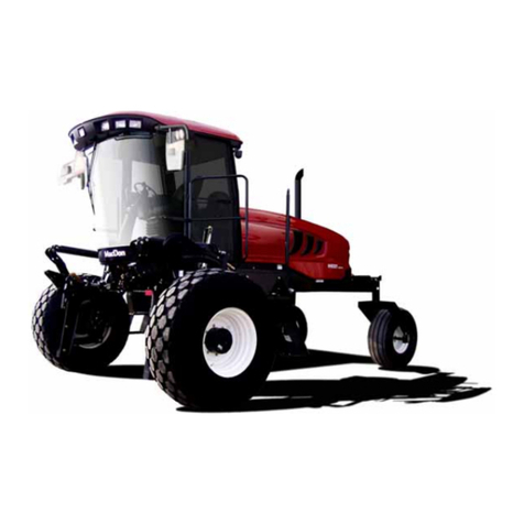
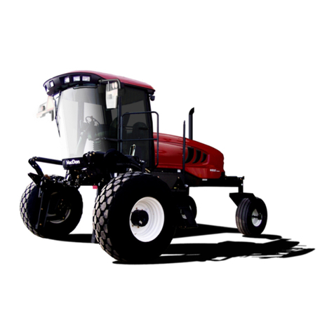
MacDon M155E4 User manual

M155E4
Self-Propelled Windrower
Unloading and Assembly Instructions (Container Shipments)
215104 Revision A
Original Instruction
The harvesting specialists.

Featuring the Dual Direction®and Ultra Glide®suspension on the M155E4.
1011662
Published in July 2019
© 2019 MacDon Industries, Ltd.
The information in this publication is based on the information available and in effect at the time of printing. MacDon
Industries, Ltd. makes no representation or warranty of any kind, whether expressed or implied, with respect to the
information in this publication. MacDon Industries, Ltd. reserves the right to make changes at any time without notice.

Introduction
This instruction manual describes the unloading, setup, and predelivery requirements for the MacDon M155E4 Self-
Propelled Windrowers shipped in containers.
Carefully read all the material provided before attempting to unload, assemble, or use the machine.
Retain this instruction for future reference.
Conventions
The following conventions are used in this document: Right and left are determined from the operator’s position. The front
of the windrower is the side that faces the crop.
NOTE:
Keep your MacDon publications up-to-date. The most current version can be downloaded from our Dealer-only site
(https://portal.macdon.com) (login required).
This instruction is available in English only and can be downloaded from our Dealer-only site.
215104 iRevision A

EC Declaration of Conformity—Windrower Lift Sling
Figure 1: EC Declaration of Conformity –Windrower Lift Sling (Page 1 of 2)
1029878
215104 ii Revision A

Figure 2: EC Declaration of Conformity –Windrower Lift Sling (Page 2 of 2)
1029879
215104 iii Revision A

EC Declaration of Conformity—Windrower Assembly Supports
Figure 3: EC Declaration of Conformity –Windrower Assembly Supports (Page 1 of 2)
1029880
215104 iv Revision A

Figure 4: EC Declaration of Conformity –Windrower Assembly Supports (Page 2 of 2)
1029881
215104 vRevision A

List of Revisions
The following list provides an account of major changes from the previous version of this document.
Section Summary of Change Internal Use Only
Introduction, page i Added statement to NOTE:
•This instruction is available in English only
and can be downloaded from our Dealer-
only site.
Tech Pubs
•EC Declaration of Conformity—Windrower
Lift Sling, page ii
•EC Declaration of Conformity—Windrower
Assembly Supports, page iv
Added new EC Declaration of Conformity
documents.
Tech Pubs
1.1 Signal Words, page 1 Added IMPORTANT and NOTE. Tech Pubs
1.7 Safety Signs, page 9
•Figure 1.12, page 9
Changed picture to black and white. Tech Pubs
2.2.1 Moving to Assembly Area –Crane Method,
page 12
•Figure 2.2, page 12
Removed references to part numbers of lift
sling decals.
ECN 56058
Tech Pubs
2.2.1 Moving to Assembly Area –Crane Method,
page 12
•Step 4, page 14
Change the block size to a single value of
152 mm (6 in.) instead of a range of
127–152 mm (5–6 in.)
Tech Pubs
2.2.2 Moving to Assembly Area –Forklift
Method, page 15
•Step 3, page 16
Change the block size to a single value of
152 mm (6 in.) instead of a range of
127–152 mm (5–6 in.)
Tech Pubs
2.5 Removing Platforms, page 23
•Step 2, page 23
Revised step and picture to identify the slings
and chain.
Tech Pubs
3.2.1 Lifting Windrower onto Stand –Crane
Method, page 32
•Figure 3.3, page 32
Removed references to part numbers of lift
sling decals.
ECN 56058
Tech Pubs
3.6 Installing Hydraulics, page 44 Replaced most of the steps and pictures. Added
information about the following:
•Wheel leg electrical harness connections.
Technical Support
3.7 Removing Battery Shipping Shield, page 52
•Step 5, page 52
Revised step to refer to the bracket. Tech Pubs
3.11 Removing Protective Covering from Exhaust
Stack, page 60
Replaced the topic “Installing Exhaust Stack”
with “Removing Protective Covering from
Exhaust Stack”because the exhaust stack
remains installed during shipping.
Tech Pubs
3.12 Installing Pre-cleaner, page 61 Removed the following WARNING ONLY
because the engine is already off at this point in
the manual:
Tech Pubs
215104 vi Revision A

Section Summary of Change Internal Use Only
•To avoid bodily injury or death from
unexpected startup of the machine, always
stop the engine and remove the key from
the ignition before leaving the operator’s
seat for any reason.
Added the procedure and pictures for opening
and closing the hood.
3.12.1 Adjusting Pre-cleaner, page 63 Added the procedure, CAUTIONS, and pictures
for opening and closing the right platform.
Tech Pubs
3.17.1 Lubrication Procedure, page 71
•Step 1, page 71
Added step:
•Shut down the engine, and remove the key
from the ignition.
Tech Pubs
3.19.1 Recording Serial Numbers, page 78
•Step 1, page 78
•Figure 3.102, page 78
•Combined two steps into one.
•Changed picture to grayscale.
Tech Pubs
3.19.2 Checking Tire Pressures, page 78
•Table 3.1, page 78
Revised tire pressure information:
•Corrected pressures for bar and turf tires.
•Tire list now includes two types of bar and
turf tires.
Tech Pubs
3.19.3 Adding Tire Ballast, page 79
•Table 3.2, page 79
Added the word “maximum”to the table title. Tech Pubs
3.19.4 Checking Engine Air Intake, page 80 Removed the following WARNING ONLY
because the engine is already off at this point in
the manual:
•To avoid bodily injury or death from
unexpected startup of the machine, always
stop the engine and remove the key from
the ignition before leaving the operator’s
seat for any reason.
Tech Pubs
3.19.5 Checking Hydraulic Oil Level, page 81 Removed the following WARNING ONLY
because the engine is already off at this point in
the manual:
•To avoid bodily injury or death from
unexpected startup of the machine, always
stop the engine and remove the key from
the ignition before leaving the operator’s
seat for any reason.
Tech Pubs
3.19.8 Checking Gearbox Lubricant Level, page
83
Removed the following WARNING ONLY
because the engine is already off at this point in
the manual:
•To avoid bodily injury or death from
unexpected startup of the machine, always
stop the engine and remove the key from
Tech Pubs
215104 vii Revision A
Section Summary of Change Internal Use Only
the ignition before leaving the operator’s
seat for any reason.
3.19.11 Replacing the Diesel Exhaust Fluid, page
84
Changed the title from “Draining and Refilling
the Diesel Exhaust Fluid Tank”to “Replacing the
Diesel Exhaust Fluid.”
Removed the following WARNING ONLY
because the engine is already off at this point in
the manual:
•To avoid bodily injury or death from
unexpected startup of the machine, always
stop the engine and remove the key from
the ignition before leaving the operator’s
seat for any reason.
Tech Pubs
3.19.13 Priming Hydraulic System, page 89
•Figure 3.129, page 92
•Step 14, page 92
•Step 15, page 92
•Figure 3.130, page 92
•Step 17, page 92
Revised steps and added new pictures to
include the model year 2020 fuse panel.
ECN 58157
3.19.13 Priming Hydraulic System, page 89
•Refer to the IMPORTANT below Step 16,
page 92
Changed the step to an IMPORTANT. Product Support
3.19.14 Checking and Adding Wheel Drive
Lubricant, page 93
•Step 5, page 93
Revised step for clarity and corrected the cross
reference.
Tech Pubs
3.19.15 Checking Traction Drive, page 93 Added NOTE:
•One person can perform this task.
Tech Pubs
3.20.1 Removing Windrower from Factory Stand,
page 95
•Step 2, page 95
Revised step and picture to show all lift lock
mechanisms.
Tech Pubs
3.20.1 Removing Windrower from Factory Stand,
page 95
•Step 3, page 95
Added CAUTION:
•Check to be sure all bystanders have cleared
the area.
Tech Pubs
4.2.1 Setting the Cab Display Language, page 99
•Step 5, page 100
Revised NOTE. Tech Pubs
4.3.2 Setting the Knife Overload Speed, page
105
Added topic introduction. Tech Pubs
4.3.3 Setting the Rotary Disc Overload Speed,
page 107
Added topic introduction. Tech Pubs
4.3.4 Setting the Hydraulic Overload Pressure,
page 108
Added topic introduction. Tech Pubs
215104 viii Revision A

Section Summary of Change Internal Use Only
4.3.7 Setting the Auto Raise Height, page 110 Added topic introduction. Tech Pubs
4.3.8 Activating the Double Windrow
Attachment, page 111
Added all steps (everything except introduction
was previously missing).
Tech Pubs
4.3.12 Activating the Swath Compressor, page
116
•Figure 4.41, page 116
•Figure 4.42, page 116
•Figure 4.44, page 117
•Revised topic introduction.
•Revised pictures.
Tech Pubs
4.3.16 Setting the Engine Intermediate Speed
Control (ISC) RPM, page 121
•Figure 4.52, page 121
Revised picture Tech Pubs
4.3.17 Clearing Sub-Acres, page 122 Split first step into two steps. Tech Pubs
4.5 Displaying Activated Cab Display Lockouts,
page 132
•Figure 4.82, page 133
Added picture. Tech Pubs
4.7 Calibrating the Swath Compressor Sensor,
page 140
•Figure 4.96, page 140
•Figure 4.97, page 140
•Figure 4.99, page 141
Revised pictures. Tech Pubs
4.8.1 Displaying the Windrower and Engine Error
Codes, page 142
•Figure 4.103, page 142
Revised picture and callouts in associated steps. Tech Pubs
5 Performing Operational Checks, page 165 Added introductory statement:
•Perform all procedures in this chapter in the
order in which they are listed.
Tech Pubs
5.7 Checking Exterior Lights, page 173 Added procedure for swiveling the operator’s
seat into cab-forward mode.
Tech Pubs
5.7 Checking Exterior Lights, page 173
•Step 5, page 174
Revised step and associated picture to include
rear floodlights.
Product Support
5.10 Checking Interior Lights, page 179
•Step 1, page 179
Changed picture. Tech Pubs
5.11 Checking Air Conditioning and Heater, page
180
•Step 4, page 180
Added step. Tech Pubs
5.13 Performing Final Steps, page 182
•Step 3, page 182
Revised step. Tech Pubs
5.13 Performing Final Steps, page 182 Removed decal part number from caption
because it is not serviceable part.
ECN 49870
215104 ix Revision A

Section Summary of Change Internal Use Only
•Figure 5.21, page 182
6.1 Attaching Header Boots, page 183
•Figure 6.1, page 183
Updated the cylinder safety prop decal to the
model year 2020 decal.
ECN 58047
6.2.1 Attaching a D Series or D1 Series Draper
Header –Hydraulic Center-Link with Optional
Self-Alignment, page 184
•Step 1, page 184
Added step:
•Shut down the engine, and remove the key
from the ignition.
Tech Pubs
6.2.1 Attaching a D Series or D1 Series Draper
Header –Hydraulic Center-Link with Optional
Self-Alignment, page 184
•Step 8, page 186
Changed picture to hide old safety prop decal. ECN 58047
6.2.1 Attaching a D Series or D1 Series Draper
Header –Hydraulic Center-Link with Optional
Self-Alignment, page 184
•Step 12, page 187
•Step 15, page 188
•Step 16, page 188
Updated the cylinder safety prop decal to the
model year 2020 decal.
ECN 58047
6.2.2 Attaching a D Series or D1 Series Draper
Header –Hydraulic Center-Link without Self-
Alignment, page 190
•Step 21, page 194
Added step:
•Shut down the engine, and remove the key
from the ignition.
Tech Pubs
6.2.2 Attaching a D Series or D1 Series Draper
Header –Hydraulic Center-Link without Self-
Alignment, page 190
•Step 9, page 192
•Corrected callouts in step.
•Changed picture to hide old safety
prop decal.
Tech Pubs
ECN 58047
6.2.2 Attaching a D Series or D1 Series Draper
Header –Hydraulic Center-Link without Self-
Alignment, page 190
•Step 14, page 193
•Step 17, page 194
•Step 18, page 194
Updated the cylinder safety prop decal to the
model year 2020 decal.
ECN 58047
6.3.1 Attaching an A Series Auger Header –
Hydraulic Center-Link with Optional Self-
Alignment, page 196
•Step 1, page 196
Added step:
•Shut down the engine, and remove the key
from the ignition.
Tech Pubs
6.3.1 Attaching an A Series Auger Header –
Hydraulic Center-Link with Optional Self-
Alignment, page 196
•Refer to the IMPORTANT on this page: NA,
page 197
•Step 12, page 199
Updated the cylinder safety prop decal to the
model year 2020 decal.
ECN 58047
215104 xRevision A

Section Summary of Change Internal Use Only
•Step 17, page 200
•Step 18, page 201
6.3.1 Attaching an A Series Auger Header –
Hydraulic Center-Link with Optional Self-
Alignment, page 196
•Step 7, page 198
Changed picture to hide old safety prop decal. ECN 58047
6.3.2 Attaching an A Series Auger Header –
Hydraulic Center-Link without Self-Alignment,
page 202
•Step 1, page 202
Added step:
•Shut down the engine, and remove the key
from the ignition.
Tech Pubs
6.3.2 Attaching an A Series Auger Header –
Hydraulic Center-Link without Self-Alignment,
page 202
•Refer to the IMPORTANT on this page: NA,
page 202
•Step 13, page 205
•Step 18, page 206
•Step 19, page 206
Updated the cylinder safety prop decal to the
model year 2020 decal.
ECN 58047
6.3.2 Attaching an A Series Auger Header –
Hydraulic Center-Link without Self-Alignment,
page 202
•Step 8, page 204
•Corrected callouts in step.
•Changed picture to hide old safety prop
decal.
Tech Pubs
ECN 58047
6.4 Attaching an R Series or R1 Series Rotary
Disc Header, page 208
Added R116 Rotary Disc Header compatibility. Product Sheet
6.4.1 Attaching an R or R1 Series Rotary Disc
Header –Hydraulic Center-Link with Optional
Self-Alignment, page 208
Changed the following statement to a
WARNING:
•To avoid bodily injury or death from
unexpected startup of the machine, always
stop the engine and remove the key from
the ignition before leaving the operator’s
seat for any reason.
Tech Pubs
6.4.1 Attaching an R or R1 Series Rotary Disc
Header –Hydraulic Center-Link with Optional
Self-Alignment, page 208
•Step 1, page 208
Added step:
•Shut down the engine, and remove the key
from the ignition.
Tech Pubs
6.4.1 Attaching an R or R1 Series Rotary Disc
Header –Hydraulic Center-Link with Optional
Self-Alignment, page 208
•Step 3, page 209
•Step 13, page 212
•Step 15, page 213
•Step 16, page 213
Updated the cylinder safety prop decal to the
model year 2020 decal.
ECN 58047
215104 xi Revision A

Section Summary of Change Internal Use Only
6.4.1 Attaching an R or R1 Series Rotary Disc
Header –Hydraulic Center-Link with Optional
Self-Alignment, page 208
•Step 8, page 211
Changed picture to hide old safety prop decal. ECN 58047
6.4.1 Attaching an R or R1 Series Rotary Disc
Header –Hydraulic Center-Link with Optional
Self-Alignment, page 208
•Step 4, page 209
Added MPORTANT:
•Before starting engine, remove protective
cover from exhaust stack.
Tech Pubs
6.4.1 Attaching an R or R1 Series Rotary Disc
Header –Hydraulic Center-Link with Optional
Self-Alignment, page 208
•Step 5, page 210
Moved IMPORTANT:
•If the center-link is too low, it may contact
the header as the windrower approaches
the header for hookup.
Tech Pubs
6.4.2 Attaching an R or R1 Series Rotary Disc
Header –Hydraulic Center-Link without Optional
Self-Alignment, page 215
•Step 1, page 215
Added step:
•Shut down the engine, and remove the key
from the ignition.
Tech Pubs
6.4.2 Attaching an R or R1 Series Rotary Disc
Header –Hydraulic Center-Link without Optional
Self-Alignment, page 215
•Step 3, page 215
•Revised step.
•Updated the cylinder safety prop decal to
the model year 2020 decal.
Tech Pubs
ECN 58047
6.4.2 Attaching an R or R1 Series Rotary Disc
Header –Hydraulic Center-Link without Optional
Self-Alignment, page 215
•Step 4, page 215
Added IMPORTANT:
•Before starting engine, remove protective
cover from exhaust stack.
Tech Pubs
6.4.2 Attaching an R or R1 Series Rotary Disc
Header –Hydraulic Center-Link without Optional
Self-Alignment, page 215
•Step 9, page 217
•Corrected callouts in step.
•Changed picture to hide old safety
prop decal.
Tech Pubs
ECN 58047
6.4.2 Attaching an R or R1 Series Rotary Disc
Header –Hydraulic Center-Link without Optional
Self-Alignment, page 215
•Step 14, page 218
•Step 16, page 219
•Step 17, page 219
Updated the cylinder safety prop decal to the
model year 2020 decal.
ECN 58047
7.3 Definitions, page 233 •Added “A30S”to the definition for “A Series
header.”
•Added the term “R1 SP Series.”
Tech Pubs
215104 xii Revision A

Section Summary of Change Internal Use Only
7.4 Lubricants, Fluids, and System Capacities,
page 236
•Footnote 20
Updated compressor part number from
MD #203013 to MD #183515.
ECN 51007
Predelivery Checklist, page 239 Changed the name of the task from “Drain and
Diesel Exhaust Fluid (DEF) tank and refill with
fresh DEF”to “Replace the diesel exhaust
fluid (DEF).”
Tech Pubs
215104 xiii Revision A


215104 xv Revision A
Introduction ................................................................................................................................................i
EC Declaration of Conformity—Windrower Lift Sling ..........................................................................................ii
EC Declaration of Conformity—Windrower Assembly Supports........................................................................... iv
List of Revisions.......................................................................................................................................... vi
Chapter 1: Safety ........................................................................................................................................ 1
1.1 Signal Words .........................................................................................................................................1
1.2 General Safety .......................................................................................................................................2
1.3 Tire Safety.............................................................................................................................................4
1.4 Battery Safety ........................................................................................................................................5
1.5 Welding Precautions ...............................................................................................................................6
1.6 Engine Safety.........................................................................................................................................7
1.6.1 High-Pressure Rail ..........................................................................................................................7
1.6.2 Engine Electronics ..........................................................................................................................7
1.7 Safety Signs ...........................................................................................................................................9
Chapter 2: Unloading the Windrower ..................................................................................................... 11
2.1 Unloading Container ............................................................................................................................. 11
2.2 Moving to Assembly Area ...................................................................................................................... 12
2.2.1 Moving to Assembly Area –Crane Method ....................................................................................... 12
2.2.2 Moving to Assembly Area –Forklift Method ..................................................................................... 15
2.3 Removing Wheel and Step Assembly........................................................................................................ 17
2.4 Removing Drive Wheels......................................................................................................................... 21
2.5 Removing Platforms.............................................................................................................................. 23
2.6 Removing Hand Rails and Exhaust Stack ................................................................................................... 25
2.7 Removing Leg Assemblies ...................................................................................................................... 26
2.8 Removing Wheel and Platform Support.................................................................................................... 29
Chapter 3: Assembling the Windrower ................................................................................................... 31
3.1 Assembling Support Stand ..................................................................................................................... 31
3.2 Lifting Windrower onto Stand ................................................................................................................. 32
3.2.1 Lifting Windrower onto Stand –Crane Method ................................................................................. 32
3.2.2 Lifting Windrower onto Stand –Forklift Method................................................................................ 33
3.3 Installing Legs ...................................................................................................................................... 35
3.4 Installing Drive Wheels .......................................................................................................................... 38
3.5 Installing Caster Wheels......................................................................................................................... 40
3.6 Installing Hydraulics .............................................................................................................................. 44
3.7 Removing Battery Shipping Shield ........................................................................................................... 52
3.8 Unpacking Ignition Keys......................................................................................................................... 53
3.9 Installing Platforms ............................................................................................................................... 55
3.10 Installing Steps ................................................................................................................................... 59
TABLE OF CONTENTS

215104 xvi Revision A
3.11 Removing Protective Covering from Exhaust Stack.................................................................................... 60
3.12 Installing Pre-cleaner ........................................................................................................................... 61
3.12.1 Adjusting Pre-cleaner .................................................................................................................. 63
3.13 Positioning Light and Mirror Assemblies ................................................................................................. 66
3.14 Installing Beacons ............................................................................................................................... 67
3.15 Installing the Slow Moving Vehicle Sign .................................................................................................. 69
3.16 Connecting Batteries ........................................................................................................................... 70
3.17 Lubricating the Windrower ................................................................................................................... 71
3.17.1 Lubrication Procedure ................................................................................................................. 71
3.17.2 Lubrication Points ...................................................................................................................... 72
3.18 Installing AM/FM Radio ....................................................................................................................... 73
3.19 Performing Predelivery Checks.............................................................................................................. 78
3.19.1 Recording Serial Numbers............................................................................................................ 78
3.19.2 Checking Tire Pressures ............................................................................................................... 78
3.19.3 Adding Tire Ballast...................................................................................................................... 79
3.19.4 Checking Engine Air Intake........................................................................................................... 80
3.19.5 Checking Hydraulic Oil Level......................................................................................................... 81
3.19.6 Checking Fuel Separator .............................................................................................................. 82
3.19.7 Checking Engine Oil Level ............................................................................................................ 82
3.19.8 Checking Gearbox Lubricant Level ................................................................................................. 83
3.19.9 Checking Engine Coolant ............................................................................................................. 84
3.19.10 Checking Air Conditioning Compressor Belt ................................................................................... 84
3.19.11 Replacing the Diesel Exhaust Fluid ............................................................................................... 84
3.19.12 Starting Engine......................................................................................................................... 86
3.19.13 Priming Hydraulic System........................................................................................................... 89
3.19.14 Checking and Adding Wheel Drive Lubricant.................................................................................. 93
3.19.15 Checking Traction Drive ............................................................................................................. 93
3.20 Removing Windrower from Stand .......................................................................................................... 95
3.20.1 Removing Windrower from Factory Stand ...................................................................................... 95
3.20.2 Removing Windrower from Field Stand .......................................................................................... 95
Chapter 4: Cab Display Module ............................................................................................................... 97
4.1 Cab Display Module –Configuration Functions .......................................................................................... 97
4.2 Cab Display Options .............................................................................................................................. 99
4.2.1 Setting the Cab Display Language.................................................................................................... 99
4.2.2 Changing the Windrower Display Units .......................................................................................... 100
4.2.3 Adjusting the Cab Display Buzzer Volume ....................................................................................... 101
4.2.4 Adjusting the Cab Display Backlighting ........................................................................................... 102
4.2.5 Adjusting the Cab Display Contrast................................................................................................ 103
4.3 Configuring the Windrower .................................................................................................................. 105
4.3.1 Setting the Header Knife Speed .................................................................................................... 105
4.3.2 Setting the Knife Overload Speed.................................................................................................. 105
4.3.3 Setting the Rotary Disc Overload Speed ......................................................................................... 107
TABLE OF CONTENTS

215104 xvii Revision A
4.3.4 Setting the Hydraulic Overload Pressure ........................................................................................ 108
4.3.5 Setting the Header Index Mode .................................................................................................... 109
4.3.6 Setting the Return to Cut Mode.................................................................................................... 109
4.3.7 Setting the Auto Raise Height....................................................................................................... 110
4.3.8 Activating the Double Windrow Attachment ................................................................................... 111
4.3.9 Activating the Hydraulic Center-Link.............................................................................................. 113
4.3.10 Activating the Rotary Disc Header Drive Hydraulics ........................................................................ 114
4.3.11 Setting the Header Cut Width..................................................................................................... 114
4.3.12 Activating the Swath Compressor................................................................................................ 116
4.3.13 Activating the Hay Conditioner ................................................................................................... 118
4.3.14 Displaying Reel Speed ............................................................................................................... 119
4.3.15 Setting the Windrower’s Tire Size................................................................................................ 120
4.3.16 Setting the Engine Intermediate Speed Control (ISC) RPM ............................................................... 121
4.3.17 Clearing Sub-Acres.................................................................................................................... 122
4.4 Activating Cab Display Lockouts ............................................................................................................ 123
4.4.1 Activating the Header Tilt Control Lockout...................................................................................... 123
4.4.2 Activating the Header Float Control Lockout ................................................................................... 124
4.4.3 Activating the Reel Fore-Aft Control Lockout................................................................................... 125
4.4.4 Activating the Draper Speed Control Lockout .................................................................................. 126
4.4.5 Activating the Auger Speed Control Lockout ................................................................................... 127
4.4.6 Activating Knife Speed Control Lockout.......................................................................................... 128
4.4.7 Activating Rotary Disc Speed Control Lockout ................................................................................. 129
4.4.8 Activating the Reel Speed Control Lockout ..................................................................................... 130
4.5 Displaying Activated Cab Display Lockouts .............................................................................................. 132
4.6 Calibrating the Header Sensors ............................................................................................................. 134
4.6.1 Calibrating the Header Height Sensor ............................................................................................ 134
4.6.2 Calibrating the Header Tilt Sensor................................................................................................. 136
4.6.3 Calibrating the Header Float Sensors ............................................................................................. 138
4.7 Calibrating the Swath Compressor Sensor ............................................................................................... 140
4.8 Troubleshooting Windrower Problems ................................................................................................... 142
4.8.1 Displaying the Windrower and Engine Error Codes........................................................................... 142
4.8.2 Switching the Installed Header Sensors ON or OFF ........................................................................... 143
4.8.3 Displaying Header Sensor Input Signals .......................................................................................... 145
4.8.4 Forcing a Header ID.................................................................................................................... 146
4.9 Troubleshooting Header Problems......................................................................................................... 148
4.9.1 Testing the Header Up/Down Activate Function Using the Cab Display Module..................................... 148
4.9.2 Testing the Reel Up/Down Activate Function Using the Cab Display Module......................................... 149
4.9.3 Testing the Header Tilt Activate Function Using the Cab Display Module.............................................. 150
4.9.4 Testing the Knife Drive Circuit Using the Cab Display Module............................................................. 152
4.9.5 Testing the Draper Drive Circuit Activate Function Using the Cab Display Module.................................. 153
4.9.6 Testing the Reel Drive Circuit Activate Function Using the Cab Display Module ..................................... 155
4.9.7 Testing the Rotary Disc Drive Circuit Activate Function Using the Cab Display Module............................ 157
4.9.8 Testing the Double Windrower Attachment Drive Activate Function Using the Cab Display
Module ............................................................................................................................. 158
TABLE OF CONTENTS

215104 xviii Revision A
4.9.9 Testing the Reel Fore-Aft Activate Function Using the Cab Display Module........................................... 160
4.9.10 Activating the Hydraulic Purge Using the Cab Display Module .......................................................... 161
Chapter 5: Performing Operational Checks........................................................................................... 165
5.1 Checking Safety System ....................................................................................................................... 165
5.2 Checking Operator's Presence System .................................................................................................... 168
5.3 Checking Windrower Startup ................................................................................................................ 169
5.4 Checking Engine Speed........................................................................................................................ 170
5.5 Checking Gauges and Cab Display Module Display.................................................................................... 171
5.6 Checking Electrical System ................................................................................................................... 172
5.7 Checking Exterior Lights....................................................................................................................... 173
5.8 Checking Auto Road Light .................................................................................................................... 177
5.9 Checking Horn ................................................................................................................................... 178
5.10 Checking Interior Lights...................................................................................................................... 179
5.11 Checking Air Conditioning and Heater .................................................................................................. 180
5.12 Checking Manuals............................................................................................................................. 181
5.13 Performing Final Steps....................................................................................................................... 182
Chapter 6: Attaching Headers ................................................................................................................ 183
6.1 Attaching Header Boots ....................................................................................................................... 183
6.2 Attaching a D Series or D1 Series Draper Header...................................................................................... 184
6.2.1 Attaching a D Series or D1 Series Draper Header –Hydraulic Center-Link with Optional Self-
Alignment.......................................................................................................................... 184
6.2.2 Attaching a D Series or D1 Series Draper Header –Hydraulic Center-Link without Self-Alignment............. 190
6.3 Attaching an A Series Auger Header....................................................................................................... 196
6.3.1 Attaching an A Series Auger Header –Hydraulic Center-Link with Optional Self-Alignment...................... 196
6.3.2 Attaching an A Series Auger Header –Hydraulic Center-Link without Self-Alignment.............................. 202
6.4 Attaching an R Series or R1 Series Rotary Disc Header............................................................................... 208
6.4.1 Attaching an R or R1 Series Rotary Disc Header –Hydraulic Center-Link with Optional
Self-Alignment.................................................................................................................... 208
6.4.2 Attaching an R or R1 Series Rotary Disc Header –Hydraulic Center-Link without Optional
Self-Alignment.................................................................................................................... 215
Chapter 7: Reference .............................................................................................................................. 221
7.1 Torque Specifications .......................................................................................................................... 221
7.1.1 SAE Bolt Torque Specifications ..................................................................................................... 221
7.1.2 Metric Bolt Specifications ............................................................................................................ 223
7.1.3 Metric Bolt Specifications Bolting into Cast Aluminum ...................................................................... 225
7.1.4 Flare-Type Hydraulic Fittings ........................................................................................................ 226
7.1.5 O-Ring Boss Hydraulic Fittings –Adjustable .................................................................................... 227
7.1.6 O-Ring Boss Hydraulic Fittings –Non-Adjustable.............................................................................. 229
7.1.7 O-Ring Face Seal Hydraulic Fittings................................................................................................ 230
7.1.8 Tapered Pipe Thread Fittings........................................................................................................ 231
TABLE OF CONTENTS
Other manuals for M155E4
5
Table of contents
Other MacDon Farm Equipment manuals

MacDon
MacDon A30-S User manual

MacDon
MacDon R85 User manual

MacDon
MacDon 2000-B User manual

MacDon
MacDon FlexDraper FD1 Series User manual

MacDon
MacDon FD75 User manual

MacDon
MacDon M105 User manual

MacDon
MacDon R80 User manual

MacDon
MacDon FD75 User manual

MacDon
MacDon D50 User manual

MacDon
MacDon M155E4 User manual

MacDon
MacDon M1 Series Technical manual

MacDon
MacDon HC10 Guide

MacDon
MacDon D50 User manual

MacDon
MacDon R85 User manual

MacDon
MacDon HC10 Guide

MacDon
MacDon A40-D User manual

MacDon
MacDon R113 SP User manual

MacDon
MacDon Crop Lifter User manual

MacDon
MacDon 802 User manual

MacDon
MacDon M1170 Parts list manual