manuals.online logo
Brands
  1. Home
  2. •
  3. Brands
  4. •
  5. Macnaught
  6. •
  7. Water Pump
  8. •
  9. Macnaught OILMASTER T512-01 User manual

Macnaught OILMASTER T512-01 User manual

T512-01(Aluminium) T512-01-11 (Zinc)
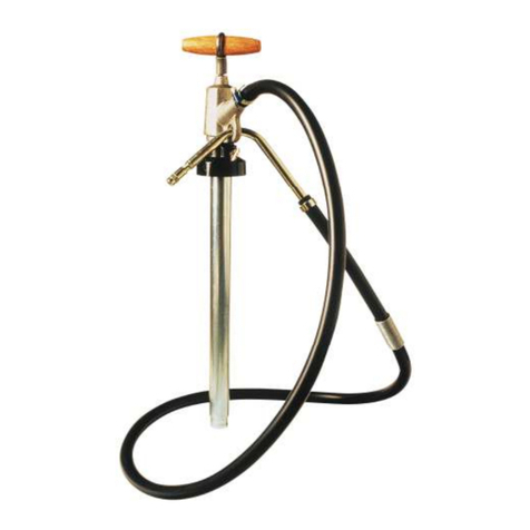
Thank you for purchasing a Macnaught air
operated oil pump. The Macnaught T512 Oilmaster is a
5:1 ratio, double action piston type stubby pump
designed to dispense lubricating oils (eg: engine oils,
hydraulic and gear oils) from bulk tanks or drums
through pipelines, hose reels and hose end oil delivery
guns with or without a flow meter.
The Oilmaster is supplied with a standard 2” BSP
adjustable bung adaptor which is suitable for most tanks
and drums. The fluid inlet of the pump is tapped 1” BSP
female(or1”NPTforUSA/Canada)soyouhavethechoice
of either supplying your own threaded suction tube or you
can purchase the optional Macnaught telescopic
suction tube kit (TB25s) which is suitable for drums or
tanks up to 1.2 metres (48”) deep.
Macnaught manufacture a full range of accessories to
suit the T512 Oilmaster, please consult your local
Macnaught reseller for more information.
With your appropriate care combined with the Macnaught
Guarantee of dependable after sales service, provided
by our worldwide distribution network, you will be assured
of continuous safe, efficient and reliable product
operation
GENERAL INFORMATION
This manual assists you in operating and maintaining
your new T512 Oilmaster. The information contained will
help you ensure many years of dependable performance
and trouble free operation.
Please take a few moments to read through this manual
before installing and operating your T512 Oilmaster
pump. If you experience problems with the product, refer
to the Maintenance and Trouble Shooting sections of this
manual. If you require further assistance please contact
your local Macnaught Distributor, Authorised Macnaught
Service Centre or Macnaught.
IMPORTANT INFORMATION
Read this information carefully before use!
Yoursafetyisimportanttous. Pleaseread,understand
and follow all safety instructions listed below. Some of
theseinstructionsalertyoutothe potential for personal
injury. ‘Cautions’listed throughout the manual advise
of potential practices or procedures which may cause
damage to your equipment.
Make sure all operators have access to adequate
instructions about safe operating and maintenance
procedures.
Do not exceed the maximum recommended air-inlet
pressure of 1035 kPa/ 150 psi/ 10.3 bar. The pump
requires a minimum air inlet pressure of 400 kPa/ 60
psi /4 bar and we recommend that you operate the unit
at 690 kPa/ 100 psi/ 6.9 bar.
Do not hit unit if it fails to operate. Refer to ‘Trouble
Shooting Guide, or return unit to your nearest
Authorised Service Centre.
Use suitable thread sealant (eg Teflon tape) on all
screwed fittings, but do not over tighten to avoid
component damage.
This pump has been fitted with a pressure release
valve. This unique feature will protect both the pump
and the system against damage created by excessive
pressure, possibly caused by thermal expansion.
INTRODUCTION
Please read and retain this instruction manual to assist
you in the operation and maintenance of this quality
product.
TB50
0206
0007
OILMASTER 5:1 OIL PUMPS
INSTRUCTION MANUAL
Most accidents occur because of a component
rupture. Be certain that any and all system
components will withstand the pressures being
developed. Never exceed the pressure rating of any
component installed in the system.
Weak, worn or damaged hoses are also a hazard.
Before each use check hose for signs of wear, leaks or
loose fittings. Tighten all fluid connections regularly
and replace weak or damaged hose. Your personal
safety and well being are at stake.
Before attempting any repairs or maintenance of this
product disconnect air supply and release oil line
pressure by squeezing hand piece/gun trigger.
Never allow any part of the human body to come
in front of or in direct contact with a material
outlet. Never point the nozzle of the gun at yourself or
anyone else.
ASSEMBLY
1) Measure the depth of the drum/tank and attach
appropriate length of 1” BSP (1” NPT USA/Canada)
threaded pipe to the inlet of the pump (or use a
Macnaught suction tube kit TB25s).
2) Remove the bung adaptor assembly from the pump
and screw into drum/tank opening. Carefully lower
the pump through bung adaptor and tighten the clamp
screw located at the clamp sleeve.
Note: There is a wire mesh strainer located in the brass
air inlet. It is recommended that a micro-fine (5 micron)
in-line air filter is fitted to the air inlet to ensure maximum
efficiency of this pump.
3) Before connecting the air supply, the user should add
a ‘stop’ compressed air cock.
Note: The air cock must be a ¼ turn type (allowing quick
closure ) and should be located close to the body of the
pump and be easily recognised.
OPERATION
1) Ensure that the drum or tank is ‘vented’.
2) Partially open the on/off air valve. The pump will
prime automatically.
3) Open the oil delivery outlet/nozzle. The pump will
automatically start.
4) Adjust on/off air valve to regulate the flow. Close
delivery outlet/nozzle to stop flow.
Caution! Do not run the pump dry. Remember to switch
air supply off if not using the pump for an extended period
e.g. at the end of each working day.
MAINTENANCE
Before carrying out any maintenance disconnect the air
supply and release the fluid pressure in the system.
Inspect your oil pump weekly for any signs of damage.
Replace any suspect or damaged parts/components as
required.
Every 2 weeks (or sooner if the pump is used every day)
apply a few drops of light oil to the air inlet of the pump.
(Sewing machine oil is ideal).
PUMP DISASSEMBLY
1) Remove oil hose from the pump unit.
2) Withdraw pump from the oil drum/tank. Use a clean
bench to carry out maintenance.
3) Remove the 4 screws (19) holding cylinder (7) to base
(14). Lever the cylinder off the base. There is a slot in
the base near the valve body (31).
4) Remove the cover screw (6) and valve body cover
(33).
5) Remove the 6 screws (35) holding the valve body (31)
to the cylinder (7). Remove the valve body assembly
and valve gasket (29).
6) Pull out the 2 brass pins (34) from the valve body.
Lever out the valve plugs (30) and (39).
7) Gently push the spool (36) out of the valve body. Be
careful when removing the O-Rings (5) and (38).
8) Remove top (long) poppet valve assembly (2), (3), (4)
and O-Rings (1), (5) and the bottom (short) poppet
valve assembly (28), (32) (3) and O’Rings (1) (5).
9) Hold hex section foot valve (27) horizontally in a vice.
Hold air piston firmly and unscrew allen head screw
(8). Remove screw and piston from piston rod.
10) Carefully unscrew the foot valve and pump cylinder
assembly (24), (25), (26) (27) from cylinder base
(14).
11) Withdraw the piston and piston road assembly from
the cylinder base.
12) Clean and inspect all parts. Replace any suspect or
worn or damaged parts.
PUMP REASSEMBLY
1) Ensure that all parts have the correct orientation. If
parts are assembled upside down, the pump will not
work. Check the parts diagram for correct orientation.
2) Apply thread sealant (Loctite or similar) to pump
cylinder thread (24) when reassembling the unit.
3) Assembly of the pump is a reversal of the disassembly
procedure.
4) Ensure that all O-Rings, particular in the valve body
(31) and poppet valve (2), (28) areas sit square.
5)Apply light grease (eg Petroleum Jelly) to O-Rings (17),
(43) and piston seals (11) before fitting cylinder (7) to
base (14).
6) Fit the pump to your oil drum/tank and reconnect
the oil hose and air supply. Open dispensing nozzle
to ensure correct operation.
WARNING
PARTS DIAGRAM
PARTS LIST
12
3
4
5
6
7
8
9
10
11
12
13 14
15
16
17 18
19 20
21
22
23
24
25
26
27
28
29
30
31
5
32
33
34
35
36
37
38
39
40
41
42
43
44
5
5
1
3
5
Do not clamp the pump tube in a vice
ORDER FOR REPLACEMENT
ITEM PART No. No. off PART/SET KIT. REF DESCRIPTION
T512-2K (KIT A) M AJOR REPAIR KIT
1 BS013 2 A O'RING
2 PA31 1 A UPPER POPPET PISTON
3 PA8 2 PA45s A POPPET SPRING
4 PA45 1 A POPPET PISTON ASSY
5 BS011 5 A O'RING
6 PA21 1 order PA44s SCREEN SCREW
7 PA35 1 PA35s AIR CYLINDER
8 N54 1 1/4" UNC 'UNBRACO'
9 N 12 9 1 1/ 4 " W A SHE R
10 PA3 1 PA26s AIR PISTON
11 PA25 2 A CUP SEAL
12 PA49 1 A SEAL
13 TB 1 1 T B 1s PIST ON R OD
14 TB39 ** 1 CYLINDER BASE (ALUMINIUM)
14 T B 3 9 - 1 .. 1 CYLINDER BASE (ZINC)
15 BS124 1 TB39S (ALUM INIUM ) A O'RING
16 TB 9 1 TB39-1s (ZINC) A OIL SEAL
17 B S 2 3 1 2 A O' R IN G
18 B S 13 4 1 A O' R IN G
19 N38 4 order PA2s incl 4xN38,4xN37 Hi-Lo SCREW
20 TB3 1 PISTON SPRING
21 TB47 1 TB48s PISTON VALVE
22 TB4 1 A "U" PACKING
23 TB48 1 PUM P PISTON
24 TB2 1 TB2s PUMP CYLINDER
25 TB8 1 FOOT VALVESPRING
26 N418 1 TB15s (ALUM INIUM ) FOOTVALVE B ALL
27 TB15 ** 1 TB15-1s (ZINC) FOOTVALVE HOUSING (ALUM INIUM )
27 TB15-1 .. 1 FOOTVALVE HOUSING (ZINC)
28 PA33S 1 PA33s LOWER POPPET VA LVE SET
29 PA38 1 order PA39s A V ALVE GASKET
30 PA93 1 order PA24s VALVEPLUG
31 PA39 1 PA39s VALVEBODY
31 PA39 1 PA30s VALVEBODY (COMPLETEASSY)
32 PA32 1 order PA33s A LOWER POPPET PISTON SET
33 PA44 1 PA44s EXHAUST SCREEN
34 PA15 2 order PA24s END PLUG PIN
35 N37 6 order PA2s incl 4xN38,4xN37 Hi-Lo SCREW
36 PA34 1 PA34s A VALVESPOOLASSY
37 PA95 1 A RESET BUTTON ASSY
38 BS012 1 order PA24s incl PA15, A O'RING
39 PA16 1 1xBS011, PA 93 END PLUG
40 TB12 1 BUNG ADAPTOR (ALUM INIUM)
40 TB12-1 1 TB12 s (A LUM INIUM ) BUNG A DA PTOR (ZINC)
41 GR10 1 TB12-1s (ZINC) CLAM P SCREW
42 TB32 1 CLAM P SLEEV E (A LUM INIUM )
42 TB31 1 CLAM P SLEEVE (ZINC)
43 BS006 2 Incl in T512-2K A O'RING
44 BS015 1 Incl in T512-2K A O'RING
** For NPT (Aluminium) order TB40s in lieu of TB39s ( & TB34s in Lieu of TB15s )
.. For NPT (Zinc) order TB40-1s in liew of TB39-1s ( & TB34-1s in liew of TB15-1s)
SPECIFICATIONS
MaximumAir Pressure
MinimumAir Pressure
TypicalAir Consumption
Noise Level
Air Inlet
PumpInlet
PumpOutlet
PumpRatio
Bung Adaptor
MaximumStaticHead
Output (at pump)
FluidsHandled
Construction
Manufacture Date
1035 kPa / 150 psi / 10.3 bar
400 kPa /60 psi / 4 bar
0.27m3per minute (9 cfm)
85Db @ 2 metres
¼” (F) NPT (Swivel Type)
1”(F) * See Below
½” (F) * See Below
5:1 (Oil Pressure is 5 times air pressure)
2” (M)
50 m/160 ft
15 litres / 3.75 US gallons per minute of SAE 10 oil @ 850 kPa/ 125 psi/ 8.5 bar
Mineral based oils (eg engine oils, gear oils,Hydraulic oils) up to SAE 140
Wetted Components: Zinc, Hard Chrome Plated Steel,Aluminium, Brass, Nitrile, Polurethane Rubber
Week/Year located on side of cylinder base
TROUBLE SHOOTING GUIDE
PROBLEM CAUSE REMEDY
1) The air leaks continuously from the
exhaust screen (33).
2) The air motor does not operate or cycle
when the reset button is pressed.
3) The air motor does not operate, but
will cycle when the reset button is
pressed.
4) The air motor cycles much faster than
normal but fails to pump oil.
5) The air motor runs slower than normal.
6) The air motor cycles intermittently
when not using the pump.
Damaged or worn air piston cup
seals (11) or air piston (10).
The lower poppet spring (3) fatigued.
a) The spool (36) is jammed in the
valve body (31).
b) The top poppet spring (3) fatigued.
The ball (26) in the foot valve is not
seated properly.
a) The air pressure is too low.
b) The air strainer is partially blocked.
a) The suction tube is not fitted
correctly.
b) The piston valve (21) is not seating
properly or the o’ring (44) is
damaged.
Replace the cup seals and piston.
Replace the bottom poppet spring.
a) Push the reset button.
1) If the motor starts, disconnect the air line
and apply 3 or 4 drops of light oil to the air
inlet of the pump.
2) If the motor does not start , replace the
spool (36), and clean the valve body bore.
Note: When re-assembled, apply 3 or 4 drops
of light oil to the air inlet of the pump.
b) Replace the top poppet spring.
a) Re-seal the suction tube to the pump with
threat sealant.
b) Check that the piston valve is seating correctly,
or replace if damaged.
a) Increase the air pressure to specifications.
(See below)
b) Clean air strainer.
Check that the footvalve ball is seating correctly.
(Clean if necessary)
* Asterisck referance to indicate relevant thread fitted. (i.e. BSP or NPT )
Note: The T512-01-11 model does not contain any Aluminium
Macnaught Pty Ltd (“Macnaught”) warrants that all Products manufactured by Macnaught and
purchasedafter1st ofJuly1999willbe free fromanydefectscausedby faultymaterialsorworkmanshipfor aperiodof(5)years
fromthedateof purchase of theproduct,providedthatduringtheWarrantyperiod:
1) Macnaughtreceivesnoticesettingoutfulldetailsofanydefectinanyproductanddetailsofthetimeandplaceofpurchase.
2) ThePurchaser, at their own cost returns the product to the nearest authorized Macnaught service center.
Forcomponentrycontained intheproduct,(suchaso’rings, seals,springsandhoses) whichare subject towear,thewarranty
periodwillbe(12)monthsfrom the date of purchase of the product.
Macnaught shall, at its option repair or replace any product found defective by its inspection.
Thiswarrantydoes notcoverfailureof partsorcomponentswhich,in thejudgmentofMacnaught,arises frommisuse,abrasion
corrosion,negligence,accident,substitutionofnon-Macnaughtparts,faultyinstallationortampering.
IfMacnaught inspection discloses nodefectinmaterial or workmanship, repairorreplacementand return will bemadeat
customarycharges.
Macnaught’sliability and thepurchaser’srights under thisWarrantyshall be limited tosuch repair or replacementandin
particular,shallnotextendtoanydirect,special,indirectorconsequentialdamageorlossesofanynature.
Theforegoingwarrantysupersedes,voidsandisinlieuofalloranyotherwarranties.
“Note:Thiswarrantydoesnotformpart of,nordoesit constitute,acontractbetweenMacnaughtandtheend-useror purchaser.
Itisadditionaltoany warranty given by the seller oftheproducts.
This warranty does not exclude, limit, restrict or modify the non-excludable rights or remedies
conferredupon theend-userorpurchaser, orthenon-excludabledutiesorliabilitiesimposedontheselleror Macnaught,byPart
V, Divisions 2 and 2Aof theTradePractices act 1974 (Commonwealth) or other legislative provisions. Macnaught otherwise
excludes,totheextentpermittedbylaw,any rights conferred on the end-user or duties orliabilitiesimposeduponit.”
WARRANTY POLICY
Macnaught Pty Ltd
POBox90ArncliffeNSW2205Australia
Telephone(02) 9567 0401
Facsimile (02) 9597 7773
Email: [email protected]
Web:www.macnaught.com.au

This manual suits for next models

1

Other Macnaught Water Pump manuals

Macnaught HVOP3 User manual

Macnaught

Macnaught HVOP3 User manual

Macnaught J3 User manual

Macnaught

Macnaught J3 User manual

Macnaught C7 User manual

Macnaught

Macnaught C7 User manual

Macnaught BOP20 BP20-PH User manual

Macnaught

Macnaught BOP20 BP20-PH User manual

Macnaught C11 User manual

Macnaught

Macnaught C11 User manual

Macnaught AFP12A User manual

Macnaught

Macnaught AFP12A User manual

Macnaught R1000 User manual

Macnaught

Macnaught R1000 User manual

Macnaught A2 User manual

Macnaught

Macnaught A2 User manual

Macnaught DP1-FPM User manual

Macnaught

Macnaught DP1-FPM User manual

Macnaught BOP60HV User manual

Macnaught

Macnaught BOP60HV User manual

Macnaught BOP20 User manual

Macnaught

Macnaught BOP20 User manual

Macnaught Lubemate L-SSRP User manual

Macnaught

Macnaught Lubemate L-SSRP User manual

Macnaught BOP20 User manual

Macnaught

Macnaught BOP20 User manual

Macnaught BOP60 User manual

Macnaught

Macnaught BOP60 User manual

Macnaught OKT583-1-001 User manual

Macnaught

Macnaught OKT583-1-001 User manual

Macnaught FTWM120-001 User manual

Macnaught

Macnaught FTWM120-001 User manual

Macnaught C4 User manual

Macnaught

Macnaught C4 User manual

Macnaught R100 User manual

Macnaught

Macnaught R100 User manual

Macnaught FTP120-001 User manual

Macnaught

Macnaught FTP120-001 User manual

Macnaught C7 User manual

Macnaught

Macnaught C7 User manual

Popular Water Pump manuals by other brands

BUSCH Mink MV 1202 A instruction manual

BUSCH

BUSCH Mink MV 1202 A instruction manual

ITT Jabsco 18580-0000 manual

ITT

ITT Jabsco 18580-0000 manual

Witt 72930024 instructions

Witt

Witt 72930024 instructions

DAB EVOSTA 110-127V Instruction

DAB

DAB EVOSTA 110-127V Instruction

Power-Pole CM2 HPU Installation

Power-Pole

Power-Pole CM2 HPU Installation

Ceco Sethco P90S quick start guide

Ceco

Ceco Sethco P90S quick start guide

ProMinent Sigma / 2 Basic S2Ba operating instructions

ProMinent

ProMinent Sigma / 2 Basic S2Ba operating instructions

HNP Mikrosysteme mzr-2542 operating manual

HNP Mikrosysteme

HNP Mikrosysteme mzr-2542 operating manual

Alcatel ADP One Series user manual

Alcatel

Alcatel ADP One Series user manual

Kayoba 650461 operating instructions

Kayoba

Kayoba 650461 operating instructions

pumpa BLUE LINE PMC1004P.1 manual

pumpa

pumpa BLUE LINE PMC1004P.1 manual

Dover Wilden Pro-Flo P4 Series Engineering, operation & maintenance

Dover

Dover Wilden Pro-Flo P4 Series Engineering, operation & maintenance

esotec Marino operating manual

esotec

esotec Marino operating manual

IWAKI PUMPS MDM Series instruction manual

IWAKI PUMPS

IWAKI PUMPS MDM Series instruction manual

Fazzini F-X50 Instructions for use

Fazzini

Fazzini F-X50 Instructions for use

Champion C46530 Owner's Manual and Operating Instructions

Champion

Champion C46530 Owner's Manual and Operating Instructions

Pentair Pool Products HYDROMATIC SP50 Installation and service manual

Pentair Pool Products

Pentair Pool Products HYDROMATIC SP50 Installation and service manual

Dekker Maxima-K 1 Series Installation, operation and maintenance manual

Dekker

Dekker Maxima-K 1 Series Installation, operation and maintenance manual

manuals.online logo
manuals.online logoBrands
  • About & Mission
  • Contact us
  • Privacy Policy
  • Terms and Conditions

Copyright 2025 Manuals.Online. All Rights Reserved.