manuals.online logo
Brands
  1. Home
  2. •
  3. Brands
  4. •
  5. Macnaught
  6. •
  7. Water Pump
  8. •
  9. Macnaught R1000 User manual

Macnaught R1000 User manual

R1000 10:1 RATIO AIR OPERATED OIL PUMP
INSTRUCTION MANUAL
Thank you for purchasing a Macnaught R1000 10:1 air
operatedoilpump.TheR100oilpumphasbeendesigned
for use in medium to large workshops where the transfer
of lubricating oils over varying distances and through
hose reels with dispensing nozzles and / or meters are
required.
Please read and retain this instruction manual to assist
you in the operation and maintenance of this quality
product.
With the appropriate care combined with the Macnaught
guarantee of dependable after sales service, provided by
its worldwide distribution network, you will be assured of
continuous safe, efficient and reliable product operation.
Macnaught also manufacture a complete range of
retractable hose reels, oil dispensing nozzles, fuel
pumps, oil pumps, positive displacement flowmeters,
greasing equipment and a complete range of
accessories.
GENERAL INFORMATION
Please take a few moments to read through this manual
before installing and operating your new R1000 oil pump. If
you experience problems with this product, refer to the
trouble shooting sections of this manual. If you require
further assistance please contact your local Macnaught
distributor or authorised Macnaught service center.
The R1000 oil pump is suitable for use with engine oil,
gear oil, automatic transmission fluid, anti-freeze/anti-
boil and compatible fluids.
IMPORTANT INFORMATION
READ THIS INFORMATION
CAREFULLY BEFORE USE
Pleaseretain this instruction manual for future reference.
Your safety is important to us. Please read, understand
and follow all safety instructions listed below. Some of
these instructions alert you to the potential for personal
injury.“Cautions”listedthroughoutthemanualadviseof
potential practices or procedures which may cause
damage to your equipment.
Make sure all operators have access to adequate
instructions about safe operating and maintenance
procedures.
Do not exceed the maximum recommended air inlet
pressure of 1035 kPa/ 150 psi / 10.3 bar. The pumps re-
quire a minimum air inlet pressure of 400 kPa / 60 psi / 4
bar and we recommend that you operate the unit at 690
kPa / 100 psi / 6.9 bar.
Donotstriketheunitifitfailstooperate.Refer to “Trouble
Shooting Guide” or return the unit to your nearest
Macnaught distributor or Authorised Macnaught Service
Centre
Use suitable thread sealant (eg. Teflon tape) on all
screwedfittings, but do not over tighten to avoid damage.
Never allow any part of the human body to come in front
of, or in direct contact with the material outlet. Never
point the nozzle of the control gun at yourself or anyone
else.
Most accidents occur because of component rupture.
Be certain that any and all system components will
withstand the pressures being developed. Never exceed
the pressure rating of any component installed in the
system.
Before attempting any repairs or maintenance of this
product disconnect the air supply and release oil line
pressure by operating hand piece / gun trigger.
OPERATION
1) Ensure the drum or tank is “vented”.
2) Partially open the on/off air valve. The pump will prime
automatically.
3) Open the delivery outlet / nozzle. The pump will start
automatically.
4) Adjust on/off air valve to regulate the flow. Close delivery
outlet/nozzle to stop flow. 1
TL020
0206
0005
Before connecting the air supply, the user should add a
‘Stop’ compressed air cock.
NOTE:The air cock mustbea 1/4 turn type(allowingquick
closure) and should be located close to the body of the
pump and be easily recognised.
INTRODUCTION
MAINTENANCE
CAUTION
Before carrying out any maintenance disconnect the air
supply and release the fluid pressure in the system.
Inspect your oil pump and associated hoses weekly for any
signs of damage. Replace any suspect or damaged parts
or components as required.
PUMP DISASSEMBLY
Note: Disconnect the air supply and release fluid
pressure.
The R1000 pump has been designed to allow the air motor
assembly, and air seal (10) to be serviced without removing
the pump from the installation.
To service theAir Motor and Piston Rod Seal
without removing pump from the installation:
1) Disconnect the air supply and release oil line pressure.
3) Pull the air motor and piston rod assembly upwards to
to allow easy access the air motor bolts (53).
7) Remove the three air valve screws (2), washers (3) and
spacers (4) from the air valve assembly, then remove air
valve cap (49).
5) Lift up the top adaptor (9) to expose the exhaust holes
located on the piston rod (41).
6) To retain the piston rod (41), insert the correct size steel
bar or pin punch into one of the exhaust holes on the
piston rod (41).
8) Unscrew the piston rod bolt (48), and remove the air
valve assembly.
Note: Ensure you do not damage piston rod (41) during
disassembly or assembly.
9) Remove the top adapter assembly (9,10,53,54,55,57)
from the piston rod.
10) Carefully remove the air seal (10), o’ring (57) and o’rings
(55) from the top adapter (9).
11) Remove body (11) and silencer (40).
12) Clean and inspect all parts. Pay special attention to the
main oil seal assembly as this can be easily damaged.
Replace any suspect, worn or damaged components.
Note: Use Loctite 222 (or similar retaining compound) on
the piston rod bolt thread (48) and the three air valve
screws (2) when re-assembling air motor.
4) Use a 6mm Allen key to unscrew the 4 air motor bolts
(53).
13) Assembly is the reversal of disassembly.
Note: Use Loctite 222 (or similar retaining compound) on
the piston rod bolt thread (48) and the three Allen screws
(2) when re-assembling the air motor.
COMPLETE PUMP DISASSEMBLY
1) Disconnect air supply and release oil line pressure.
2) Remove oil discharge hose from pump outlet.
3) Withdraw pump from the oil drum/tank. (Use a clean
bench to carry out maintenance).
4) Hold the bottom adaptor firmly in a vice and carefully
unscrew and remove the pump tube (20) assembly.
Note:Care should be taken not damageairmotor housing
during disassembly.
5) For air motor disassembly see previous section “Pump
Disassembly”, To service the air motor and piston rod
seal section follow items 2 - 12 on this page.
6) Using a suitable size pin punch (1/8”) remove the roll pin
(36) from the Piston rod (41).
7) Unscrew and remove the joining pin (35), valve housing
(23) and piston assembly from the piston rod (41).
9) Remove the piston rod (41) from the bottom adapter (15).
10) Unscrew and remove and the oil seal assembly (14).
11) Remove foot valve assembly (28) from the pump tube
(20).
12) Dismantle foot valve assembly.
PUMP ASSEMBLY
1) Clean and inspect all parts. Replace any, suspect, worn
or damaged parts.
2) Ensure that all parts have the correct orientation. If
parts are assembled upside down, the pump will not
work. Check the parts diagram for correct orientation.
2) Either use a strap pipe wrench to carefully unscrew and
remove the air motor housing (50), or use two correct
size steel bars or pin punches and insert them into the
holes located on the top of the air motor cap (1). Hold
both steel bars or pin punches in position. Place a screw
driver in between the two bars or punches and unscrew
the air motor cap anti-clockwise.
Use Loctite 222 (or similar retaining compound) when
assembling the pump piston (26) to the valve housing
(23).
Ensure correct orientation when fitting the oil seal (38),
be careful you do not damage the seal during assembly.
8) Dismantle the valve housing (23) and piston assembly
(26).
3) Assembly of the pump is a reversal of the disassembly
procedure.
4) Fit the pump to your drum/tank and re-connect the oil
hose and air supply. Open dispensing nozzle to ensure
correct operation.
2
Do not run the pump dry. Remember to switch off the air
supplyif the pump isnot being used for extendedperiods.
(e.g. at the end of each working day)
CAUTION
3
PARTS DIAGRAM PARTS LIST
1
2
3
4
6
5
7
8
9
10
11
12
13
14
15
16
17
18
19
20
21
22
23
24
25
26
28
29
30
31
32
27
33
34
35
36
37
38
39
40
41
42
43
44
45
46
47
48
49
50
51
52
53
54
55
56
57
58
ORDER FOR REPLACEMENT
Item Part no No off Part or Set Kit ref Description
TL01-1K (A) OVERHAUL SEAL KIT
TG01-2K (B) AIR MOTOR OVERHAUL KIT
TL01-3K (C) LOWER PUM P SERVICE KIT
1 TG001 1 TG001sincl BS045 AIR MOTOR CAP
2 N35 3 B AIRVALVESCREW
3 N117 3 B AIRVALVEWASHER
4 TG031 3 B AIRVALVESPACER
5 BS016 3 A B O'RING
6TC38 1 B SPRING
7 TG007 1 B SPRING
8 TG008 1 B RETAINER
9 TG010 1 TG010s TOP ADAPTOR (BSP)
9 TG021 1 TG021s TOP ADAPTOR (NPT)
10 TG012 1 A B AIR M OTOR SEAL
11 TE006 1 TE006s inclTE020 BODY
12 N 3 55 1 PIN
13 BS132 1 TL006s A C O'RING
14 TL006 1 incl 38, 39 OIL SEAL CARRIER
15 TL003 1 TL003s BOTTOM ADAPTOR (BSP)
15 TL004 1 TL004s BOTTOM ADAPTOR (NPT)
16 BS128 1 A C O'RING
17 TE026 1 STAR NUT
18 TL008 1 TL008As incl TL009 SPACER
19 TE024 1 LOWER BUNG NUT
20 TL002 1 TL002s SUCTION TUBE (STUB)
20 TL015 1 TL015s SUCTION TUBE (DRUM)
21 N404 1 STEELBALL5/32"
22 TB3 1 SPRING
23 TL012 1 TL012s VALVE HOUSING
24 TB47 1 PRESSURE RELIEF VALVE
25 TB46 1 SPRING
26 TL011 1 PUM P PISTON
27 TD35 1 C FOOTVALVE SPRING
28 TL013 1 TL013s Kits Include FOOTVALVE (STUB) BSP
28 TL014 1 TL014s TD35, N418, FOOTVALVE (STUB) NPT
28 TL019 1 TL019s BS026, N355 FOOTVALVE (DRUM )
29 N415 1 C STEEL BALL 7/8"
30 TG011 3 A RUBBERBUSH
31 TL010 1 A C PLUNGER SEAL
32 BS015 1 A C O'RING
33 PA16 1 A C RESET END PLUG
34 N349 1 A C PIN
35 TF004 1 TF004s incl N349, N350 JOINING PIN (STUB)
35 TF014 1 TF014s incl N349,N350 JOININGPIN (DRUM)
36 N350 1 A C PIN
37 BS045 1 A B O'RING
38 TL005 1 A C OIL SEAL
39 TL007 1 A C GUIDERING
40 TE020 1 order TE006s SILENCER
41 TL001 1 TL001s PISTON ROD
42 TG036 1 B SPACER
43 TG030 1 B SEALPLATE
44 TG032 1 B WASHER
45 BS343 1 A B O'RING
46 TG004 1 B PISTON
47 TG005 1 B WASHER
48 TG003 1 B PISTON ROD BOLT
49 TE011 1 A B AIR VALVECAP
50 TG002 1 TG002s incl BS045,BS046 AIR MOTOR HOUSING
51 TE003 1 TE002s B BUFFER STOPPER
52 TE002 1 B SPRING
53 TE004 4 BOLT
54 N104 4 TE004s WASHER
55 BS011 4 A O'RING
56 TL009 1 A WEATHER SEAL
57 BS046 1 A B O'RING
TROUBLE SHOOTING
SPECIFICATIONS
4
TROUBLE CAUSE REMEDY
Air motor operates without 1. Drumor tank is empty 1. Change drumor fill tank
pressing trigger 2. Foreign matter in footvalve (28) 2. Remove footvalve, clean and
reassemble
Air motor operates but little 1. Drumor tank is empty 1. Change drumor fill tank
or no oil flows 2. Foreign matter in footvalve (28) 2. Remove footvalve, clean and
reassemble
3. Faulty plunger (23) / piston 3. Inspect plunger assembly and replace
(26) assembly damaged or faulty parts
Air continuously leaks 1. Air seal (10) worn or damaged 1. Replace air seal (10)
through the exhaust 2. Air valve cap (49) is worn or 2. Replace air valve cap (49) and Spring (52)
damaged
3. O'ring (55) under the air motor 3. Replace damaged o,ring (55)
bolts (53) are leaking
Oil leaks through the exhaust Oil seal (38) is worn or damaged Replace oil seal (38)
Pump is operating erraticaly 1. Suction tube is sucking air 1. Re-sealthe suction. (use either Teflon
and there is air in the oil tape or suitable thread sealant)
2. Pump tube (20) of Footvalve 2. Re-seal the pump tube (20) or footvalve (28).
is sucking air ( Use eitherTeflon tape or suitable thread sealant
)
Air Motor 104.7mm (4.12") diameter
Maximum Air Pressure 1035kPa / 150psi / 10.3Bar
Minimum Air Pressure 400kPa / 60psi / 4Bar
Air Consumption 18cfm/min
Output (At The Pump) 15 litres / minute of SAE10 oil @ 100psi
Maximum Suction Head 5metres
Maximum Static Head 1000metres / 3200ft
Air Inlet Thread 1/4" NPT
Pump outlet Thread 3/4" BSP(3/4" NPT USA)
Pump Intlet Thread 3/4" BSP(3/4" NPT USA)
Bung Adapter Thread 2" (M)
Wetted Components Aluminium, Nitrile Rubber, Zinc plated carbon steel, Carbon PTFE
Dimensions R1000S (stub) 605 x 120 x 120
R1000T (drum) 1297 x 120 x 120
Weight R1000S (stub) 6kg
R500T (drum) 7.2kg
MacnaughtPtyLtd (“Macnaught”)warrantsthatallProducts manufacturedbyMacnaughtand
purchasedafter 1st of July 1999willbefree from any defectscausedbyfaulty materials or
workmanshipforaperiodof(5)yearsfromthedateofpurchase of the product, provided that
duringtheWarrantyperiod:
1) Macnaughtreceives notice settingoutfull details ofanydefect in anyproductand
detailsofthetimeandplaceofpurchase.
2) ThePurchaser,attheirowncostreturnstheproducttothenearestauthorized Macnaught
servicecenter.
Forcomponentrycontainedin the product,(suchaso’rings,seals,springsandhoses ) which
aresubjecttowear,thewarrantyperiodwillbe(12)monthsfromthe date of purchase of the
product.
Macnaughtshall,atitsoptionrepairorreplaceanyproductfounddefectivebyitsinspection.
Thiswarrantydoesnotcoverfailureofpartsorcomponentswhich,inthejudgmentofMacnaught,
arisesfrommisuse,abrasioncorrosion, negligence, accident,substitutionofnon-Macnaught
parts,faultyinstallationortampering.
IfMacnaughtinspection disclosesnodefectinmaterial orworkmanship,repairorreplacement
andreturnwillbemadeatcustomarycharges.
Macnaught’sliabilityandthepurchaser’s rights under this Warranty shallbelimitedtosuch
repairor replacement andin particular, shallnot extend toany direct, special,indirector
consequentialdamageorlossesofanynature.
Theforegoingwarrantysupersedes,voidsand is in lieu ofalloranyotherwarranties.
“Note:Thiswarrantydoesnotformpartof,nordoesitconstitute,acontractbetweenMacnaught
andtheend-userorpurchaser.Itisadditionaltoanywarrantygivenbytheselleroftheproducts.
Thiswarrantydoesnotexclude, limit, restrict ormodifythenon-excludablerightsorremedies
conferredupontheend-userorpurchaser, or the non-excludabledutiesorliabilitiesimposed
onthe seller orMacnaught,by Part V,Divisions2and 2AoftheTradePracticesact1974
(Commonwealth)orotherlegislative provisions.Macnaughtotherwiseexcludes,totheextent
permittedbylaw,anyrightsconferred on the end-userordutiesorliabilitiesimposeduponit.”
WARRANTY POLICY
Macnaught Pty Ltd
POBox90ArncliffeNSW2205Australia
Telephone(02) 9567 0401
Facsimile (02) 9597 7773
Email: [email protected]
Web:www.macnaught.com.au

Other Macnaught Water Pump manuals

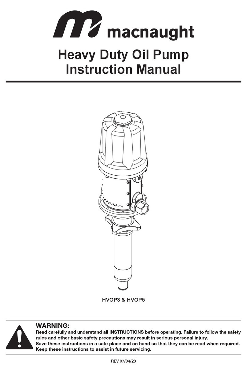
Macnaught OKT583-1-001 User manual

Macnaught

Macnaught OKT583-1-001 User manual

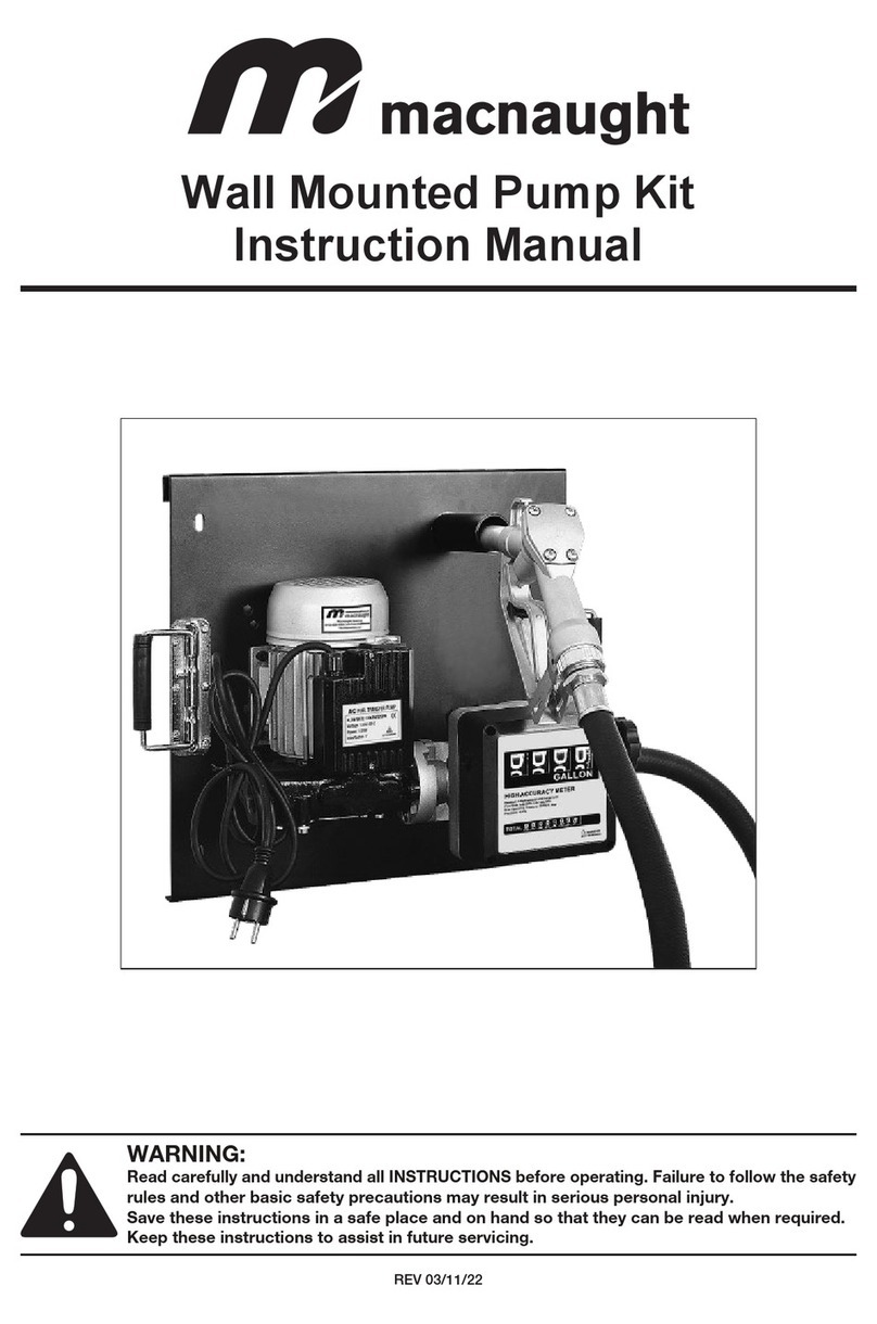
Macnaught R100 User manual

Macnaught

Macnaught R100 User manual

Macnaught J3 User manual

Macnaught

Macnaught J3 User manual

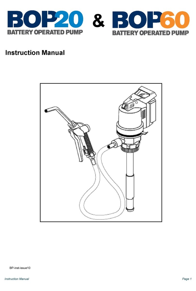
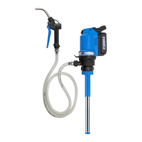
Macnaught BOP60 User manual

Macnaught

Macnaught BOP60 User manual

Macnaught BOP20 User manual

Macnaught

Macnaught BOP20 User manual

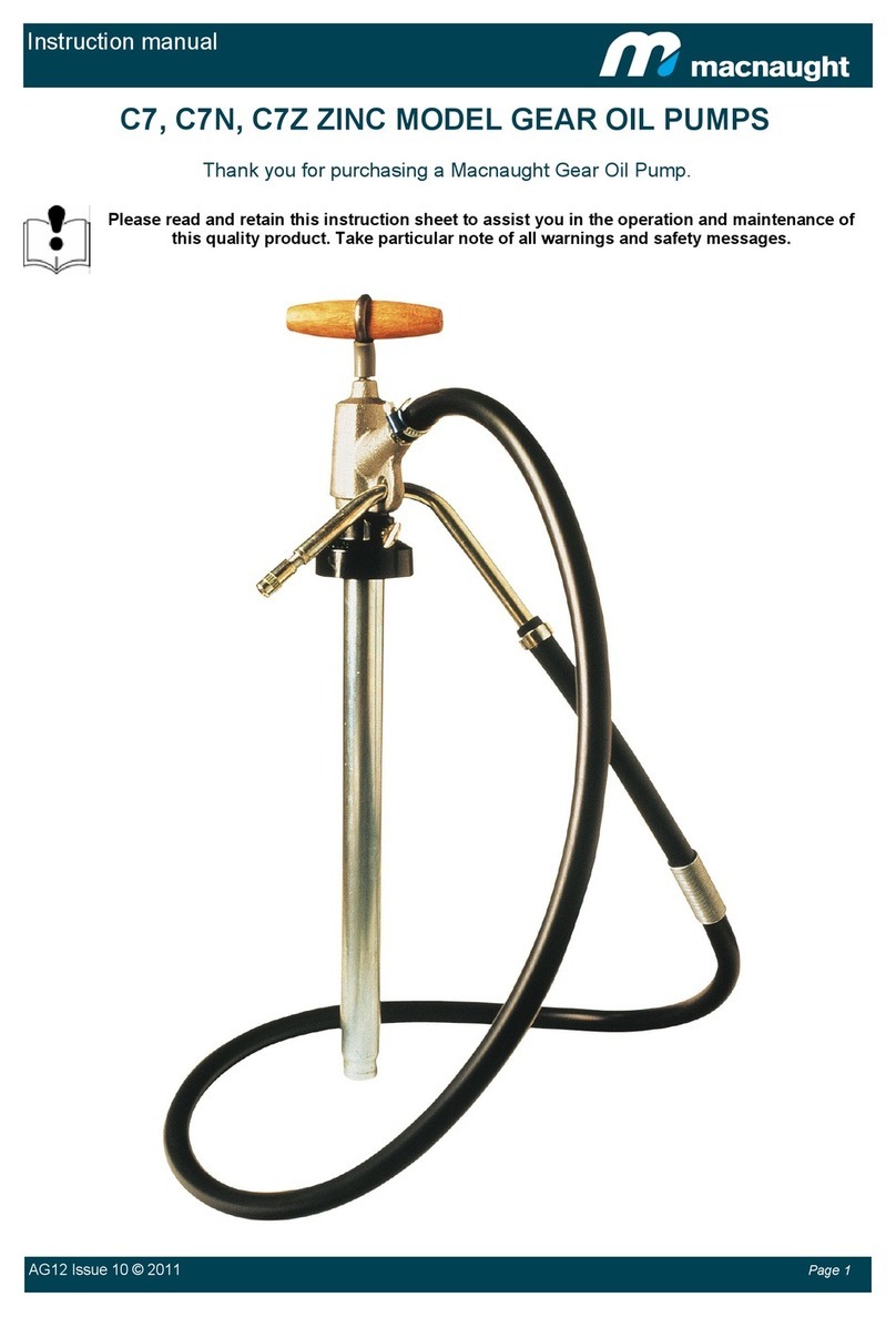
Macnaught C7 User manual

Macnaught

Macnaught C7 User manual

Macnaught FTP120-001 User manual

Macnaught

Macnaught FTP120-001 User manual

Macnaught BOP60HV User manual

Macnaught

Macnaught BOP60HV User manual

Macnaught A2 User manual

Macnaught

Macnaught A2 User manual

Macnaught C7 User manual

Macnaught

Macnaught C7 User manual

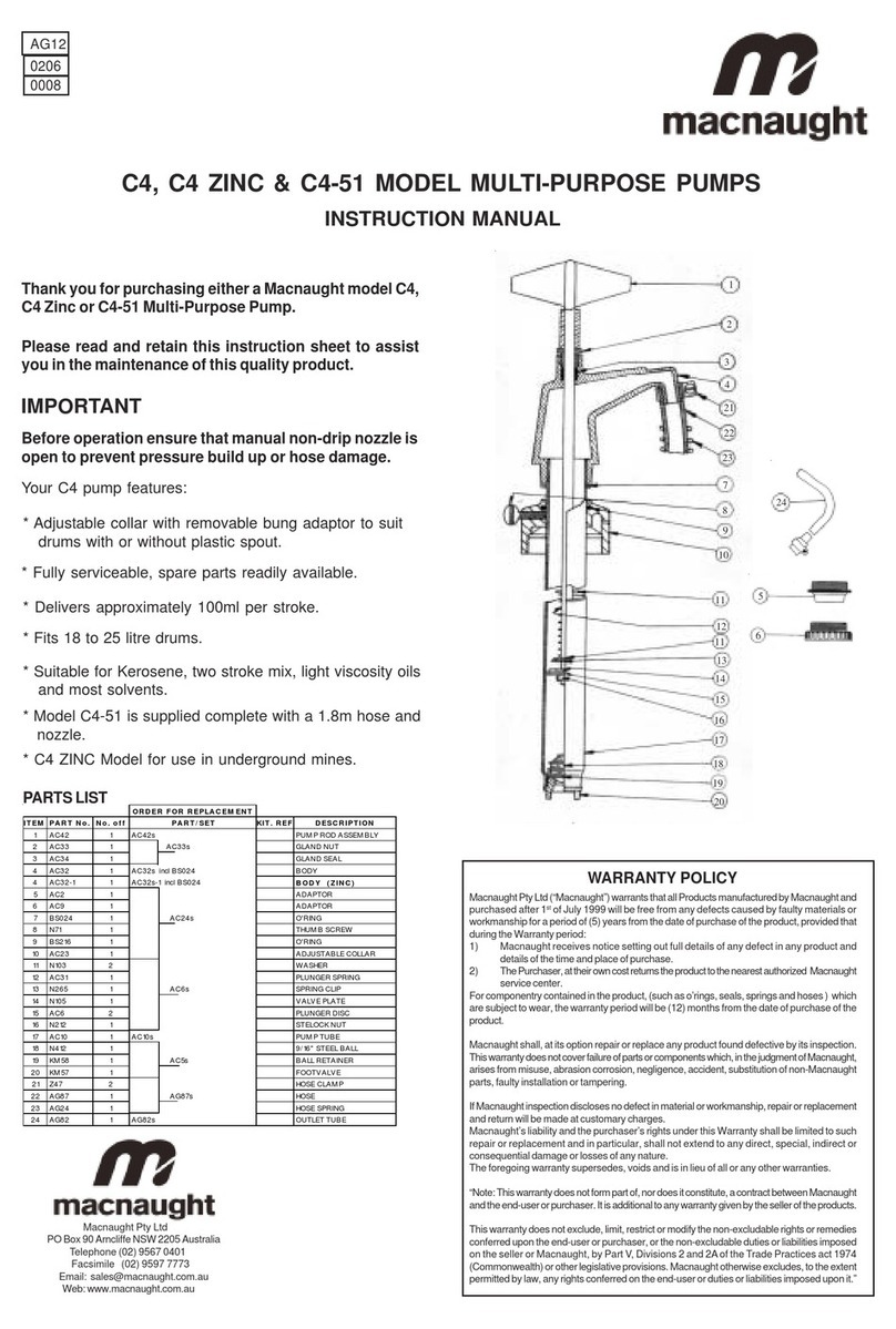
Macnaught C4 User manual

Macnaught

Macnaught C4 User manual

Macnaught AFP12A User manual

Macnaught

Macnaught AFP12A User manual

Macnaught BOP20 BP20-PH User manual

Macnaught

Macnaught BOP20 BP20-PH User manual

Macnaught DP1-FPM User manual

Macnaught

Macnaught DP1-FPM User manual

Macnaught HVOP3 User manual

Macnaught

Macnaught HVOP3 User manual

Macnaught OILMASTER T512-01 User manual

Macnaught

Macnaught OILMASTER T512-01 User manual

Macnaught C11 User manual

Macnaught

Macnaught C11 User manual

Macnaught BOP20 User manual

Macnaught

Macnaught BOP20 User manual

Macnaught Lubemate L-SSRP User manual

Macnaught

Macnaught Lubemate L-SSRP User manual

Macnaught FTWM120-001 User manual

Macnaught

Macnaught FTWM120-001 User manual

Popular Water Pump manuals by other brands

KSB Amarex KRT Installation & operating manual

KSB

KSB Amarex KRT Installation & operating manual

BOC Edwards E1M275S instruction manual

BOC Edwards

BOC Edwards E1M275S instruction manual

Festool VAC SYS VP Original operating manual/spare parts list

Festool

Festool VAC SYS VP Original operating manual/spare parts list

Time Electronics 7195 user manual

Time Electronics

Time Electronics 7195 user manual

Grundfos PS.R.05-17 Installation and operating instructions

Grundfos

Grundfos PS.R.05-17 Installation and operating instructions

Watson Marlow Pumps 600 Series Installation, operating and maintenance manual

Watson Marlow Pumps

Watson Marlow Pumps 600 Series Installation, operating and maintenance manual

Pfeiffer Vacuum HiPace 800 P operating instructions

Pfeiffer Vacuum

Pfeiffer Vacuum HiPace 800 P operating instructions

ASP FSPO Installation, operation and maintenance instructions

ASP

ASP FSPO Installation, operation and maintenance instructions

BOC Edwards Seiko Seiki STP A803 instruction manual

BOC Edwards

BOC Edwards Seiko Seiki STP A803 instruction manual

Biral A 12 Installation and operating instructions

Biral

Biral A 12 Installation and operating instructions

GORMAN-RUPP 14A2-B Installation, operation and maintenance manual

GORMAN-RUPP

GORMAN-RUPP 14A2-B Installation, operation and maintenance manual

ARO PE05P-X-X-B0S Series Operator's manual

ARO

ARO PE05P-X-X-B0S Series Operator's manual

PREMIER TECH Rewatec RVPS1800 Owner's manual and installation guide

PREMIER TECH

PREMIER TECH Rewatec RVPS1800 Owner's manual and installation guide

Adam Pumps PA1 70A Use and maintenance manual

Adam Pumps

Adam Pumps PA1 70A Use and maintenance manual

Baoding Longer Precision Pump Longer BT300-1F operating manual

Baoding Longer Precision Pump

Baoding Longer Precision Pump Longer BT300-1F operating manual

Dover PSG All-Flo C050 Installation, operation & maintenance manual

Dover

Dover PSG All-Flo C050 Installation, operation & maintenance manual

Sethco ZKX 3/4CS operating instructions

Sethco

Sethco ZKX 3/4CS operating instructions

Thermo Scientific 420-1901 operating manual

Thermo Scientific

Thermo Scientific 420-1901 operating manual

manuals.online logo
manuals.online logoBrands
  • About & Mission
  • Contact us
  • Privacy Policy
  • Terms and Conditions

Copyright 2025 Manuals.Online. All Rights Reserved.