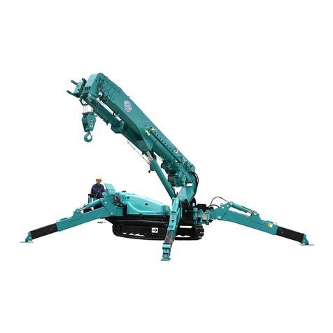
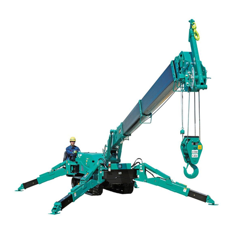
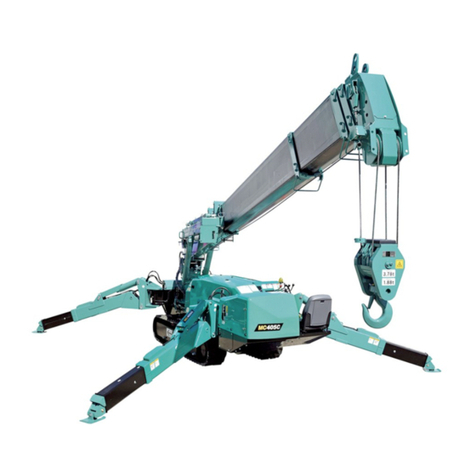
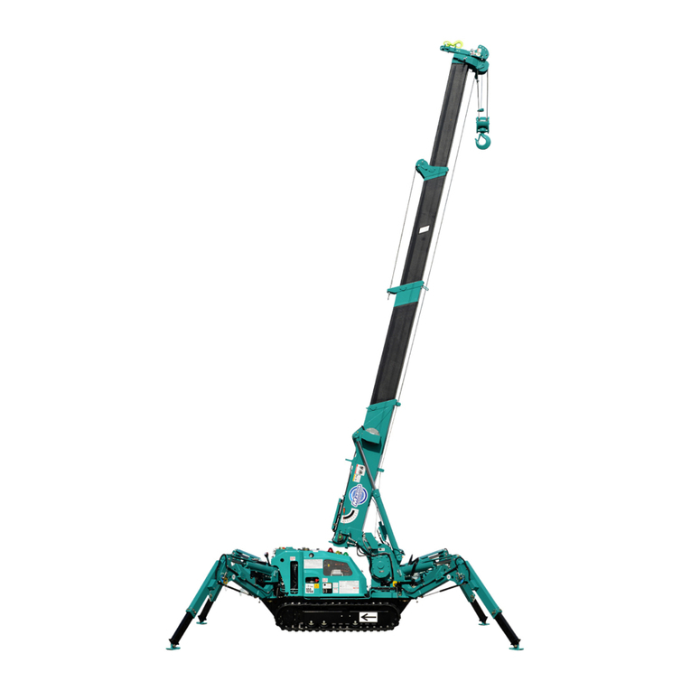
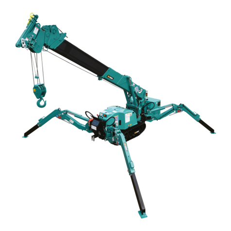
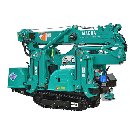
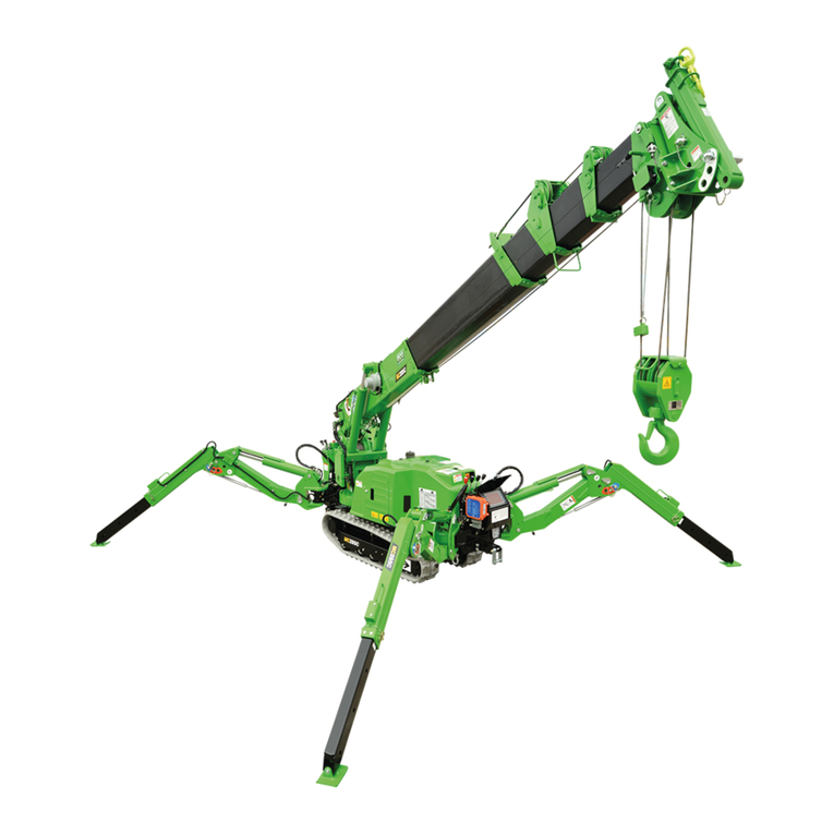
Maeda HIRD MC815 User manual

OPERATORS MANUAL
MAEDA MINI CRANE
MC815
www.hird.co.uk
DISCLAIMER - ALL INSTRUCTIONS ARE SUPPLIED FROM MANUFACTURER AND WHERE CORRECT AT TIME OF PRINT OM 1704-2
Northern (Head Office)
Tel: +44 (0)1482 227333
Western
Tel: +44 (0)1384 900388
Southern
Tel: +44 (0)203 174 0658
Central
Tel: +44 (0)1302 341659

i
CONTENTS
Item Page
INTRODUCTION 1
1. INTRODUCTION 2
2. FOR SAFE USE OF THE MACHINE 3
3. MACHINE OVERVIEW 4
3.1 SPECIFIED OPERATIONS 4
3.2 MACHINE STRUCTURE 4
3.3 MACHINE FUNCTIONS 5
4. QUALIFICATION FOR OPERATION 6
4.1 QUALIFICATION FOR CRANE OPERATION 6
5. TERMINOLOGY 7
5.1 TERMS AND DEFINITIONS 7
5.2 DIAGRAM OF WORKING RADIUS AND LIFTING HEIGHT 8
5.3 RATED TOTAL LOAD CHART 9
5.4 HOW TO LOOK AT THE ANGLE INDICATOR 15
6. OUTLINE OF REMOTE CONTROLLER 16
6.1 FEATURE 16
6.2 CONFIGURATION 16
6.2.1 CONFIGURATION OF REMOTE CONTROLLER 16
6.3 FUNCTIONS 17
6.3.1 FUNCTIONS OF REMOTE CONTROLLER 17
7. DPF OVERVIEW 18
7.1 DPF FUNCTION 18
7.2 DPF REGENERATION 18
SAFETY 21
1. BASIC PRECAUTIONS 22
2. PRECAUTIONS ON HANDLING REMOTE CONTROL SYSTEM 27
3. PRECAUTIONS FOR USE OF ENGINE AND ELECTRIC MOTOR SPECIFICATIONS 31
4. OPERATION RELATED PRECAUTIONS 32
4.1 BEFORE STARTING ENGINE 32
4.2 AFTER STARTING ENGINE 34
4.3 DURING CRANE WORK 39
4.4 PRECAUTIONS FOR TERMINATING CRANE OPERATION (REMOTE CONTROL
SYSTEM) 50
5. TRANSPORT PRECAUTIONS 51
6. BATTERY HANDLING PRECAUTIONS 53
7. MAINTENANCE PRECAUTIONS 55
7.1 PRECAUTIONS BEFORE MAINTENANCE 55
7.2 PRECAUTIONS DURING MAINTENANCE 57
8. SAFETY LABEL LOCATIONS 62

ii
Item Page
OPERATION 73
1. NAME OF EACH SECTION 74
1.1 MACHINE UNITS 74
1.2. DESCRIPTION OF CONTROLS 75
1.2.1. DESCRIPTION OF MONITOR 76
1.2.2. NAMES AND DESCRIPTION OF CONTROL LEVERS 98
1.2.3 NAMES AND DESCRIPTION OF OUTRIGGER OPERATION PANEL 103
1.2.4 EMERGENCY STOP SWITCH 104
1.2.5 STARTER SWITCH 104
1.2.6 LOCK LEVER 104
1.2.7 ACCELERATOR PEDAL 104
1.2.8 LIGHT SWITCH 105
1.2.9 DISCONNECT SWITCH 105
1.2.10 OVERRIDE SWITCH 106
1.2.11 FUSE BOX 107
1.2.12 CIGAR SOCKET 108
1.2.13 MAIN TENANCE USB PORT 108
1.3 NAMES AND DESCRIPTION OF REMOTE CONTROL PARTS 109
1.3.1. TRANSMITTER AND RECEIVER 109
1.3.2 DESCRIPTION OF REMOTE CONTROLLER ACCESSORIES 113
1.4. OUTRIGGER SAFETY DEVICE 114
1.4.1 FUNCTIONS OF OUTRIGGER SAFETY DEVICES 114
1.5 MOMENT LIMITER (OVERLOAD DETECTOR) 115
1.5.1 CONFIGURATION OF MOMENT LIMITER 115
1.5.2 FUNCTIONS OF MOMENT LIMITER 116
1.5.3 MOMENT LIMITER OPERATION 117
1.5.4 MOMENT LIMITER SETTINGS 119
1.5.5 MOMENT LIMITER FUNCTIONS 122
1.5.6 MOMENT LIMITER START CONDITIONS 125
1.5.7 OVERRIDE SWITCH 126
1.5.8 TROUBLESHOOTING FOR MOMENT LIMITER 126
1.6 OVER HOIST DETECTOR 127
1.7 OPERATOR SEAT 128
1.8 RADIATOR COVER 130
1.9 RADIATOR GRILLE 131
1.10 ENGINE COVER 132
1.11 MACHINERY COVER 133
1.12 OPERATION SIDE COVER 134
1.13 POWER UNIT 135
1.13.1 NAMES OF POWER UNIT PARTS 135
1.13.2 NAMES OF POWER SUPPLY BOX PARTS 135
1.13.3 NAMES OF INVERTER PARTS 136

iii
Item Page
2. OPERATION 137
2.1 PRE-OPERATION INSPECTION 137
2.1.1 VISIBLE CHECKS 137
2.1.2 CHECKING BEFORE STARTING ENGINE 137
2.1.3 INSPECTION AFTER STARTING ENGINE 137
2.2 STARTING ENGINE 138
2.2.1 NORMAL STARTING OF ENGINE 138
2.2.2 STARTING ENGINE IN COLD ENVIRONMENT 139
2.3 OPERATIONS AND CHECKS AFTER STARTING ENGINE 140
2.4 BREAK-IN OPERATION 142
2.5 MACHINE TRAVELLING POSTURE 142
2.6 START MOVING MACHINE 143
2.7 CHANGING MACHINE TRAVELLING MODE 144
2.8 CHANGING DIRECTION OF THE MACHINE 144
2.9 STOPPING/PARKING THE MACHINE 146
2.10 STOPPING ENGINE 147
2.11 INSPECTION AFTER STOPPING ENGINE 147
2.12 CAUTIONS IN DRIVING 148
2.13 OUTRIGGER/CRANE RELATED SAFETY DEVICES 150
2.14 OUTRIGGER SETTING OPERATION 153
2.14.1 OUTRIGGER COMPONENTS 155
2.14.2 OUTRIGGER SETUP OPERATION 155
2.15 CAUTIONS BEFORE CRANE OPERATION 160
2.16 OPERATION BEFORE CRANE WORK 161
2.17 CRANE OPERATION POSTURE 162
2.18 WINDING AND UNWINDING 163
2.19 BOOM DERRICKING OPERATION 163
2.20 BOOM TELESCOPING OPERATION 164
2.21 SLEWING OPERATION 165
2.22 ACCELERATOR OPERATION 165
2.23 CRANE STOWAGE OPERATION 166
2.24 OUTRIGGER STOWAGE OPERATION 169
2.25 PROHIBITED OPERATIONS DURING CRANE WORK 173
2.26 PICK & CARRY OPERATION 175
2.26.1 CAUTIONS DURING PICK & CARRY OPERATION 175
2.26.2 PICK & CARRY POSTURE 176
2.26.2.1 CHANGE TO PICK & CARRY POSTURE FROM TRAVELLING
POSTURE 176
2.26.2.2 CHANGE TO PICK & CARRY POSTURE FROM CRANE MODE
POSTURE 177
2.26.3 PICK & CARRY OPERATIONS 178
2.26.4 CANCELING PICK & CARRY OPERATION POSTURE 179
2.26.4.1 HOW TO RETURN TO TRAVELLING POSTURE 179
2.26.4.2 HOW TO RETURN TO CRANE POSTURE 180
2.27 DPF STATIONARY REGENERATION METHOD 181

iv
Item Page
3. OPERATION BY REMOTE CCONTROL 182
3.1 CAUTIONS BEFORE OPERATION 182
3.2 POWERING ON 183
3.3 INDICATIONS OF DISPLAY 184
3.4 STARTING/STOPPING THE ENGINE 188
3.5 OPERATION AFTER ENGINE IS STARTED 188
3.5.1 OPERATION BEFORE WORK 188
3.5.2 SWITCHING OPERATION MODE 188
3.6 TRAVEL OPERATION 189
3.6.1 START MOVING MACHINE 189
3.6.2 CHANGING DIRECTION OF THE MACHINE 190
3.6.3 STOPPING/PARKING THE MACHINE 191
3.7 OUTRIGGER OPERATION 192
3.7.1 OUTRIGGER SETTING OPERATION 193
3.7.2 OUTRIGGER STOWAGE OPERATION 196
3.8 CRANE OPERATION 199
3.8.1 HOOK WINDING AND UNWINDING 200
3.8.2 BOOM DERRICKING OPERATION 200
3.8.3 BOOM TELESCOPING OPERATION 201
3.8.4 SLEWING OPERATION 202
3.8.5 OPERATION WHILE TRAVELING WITH A SUSPENDED LOAD 203
3.8.6 FLY JIB DERRICKING/TELESCOPING OPERATION 203
3.9 OPERATING SPEED SELECTOR/OUTRIGGER SELECT SWITCH 204
3.10 OPERATING ACCELERATOR CONTROL SWITCH 204
3.11 OPERATING HORM SWITCH 204
3.12 EMERGENCYSTOP SWITCH OPERATION 205
3.13 LED LIGHT OPERATIONS 205
3.14 CHECKING AFTER CRANE OPERATION 206
3.14.1 CRANE STOWAGE OPERATION 206
3.14.2 STOPPING OPERATION BY RADIO CONTROL AND INSPECTION 206
4. OPERATING MACHINE WITH ENGINE & ELECTRIC MOTOR 207
4.1 POWER SUPPLY CONNECTION 207
4.2 OPERATION AND CHECKING AFTER POWER CONNECTION 210
4.3 MACHINE OPERATION 212
4.4 MACHINE STOP AND CHECKS AFTER STOPPING MACHINE 212
4.5 POWER SUPPLY SEPARATION 213
5. HANDLING WIRE ROPE 214
5.1 CRITERIA FOR WIRE ROPE REPLACEMENT 214
5.2 CORRETIVE ACTIONS AGAINST TWISTED WIRE ROPE 215
6. TRANSPORTATION 217
6.1 LOADING/UNLOADING 217
6.2 HOISTING MACHINE 218
6.3 CAUTIONS WHEN LOADING MACHINE 219
6.4 CAUTIONS DURING TRANSPORTATION 219

v
Item Page
7. HANDLING MACHINE IN COLD ENVIRONMENT 220
7.1 PREPARING FOR LOW TEMPERATURE 220
8. LONG-TERM STORAGE 222
8.1 BEFORE STORING MACHINE 222
8.2 DURING STORAGE 222
8.3 AFTER STORAGE 223
9. HANDLING BATTERY 224
9.1 CAUTIONS IN HANDLING BATTERY 224
9.2 REMOVING/INSTALLING BATTERY 225
9.3 CAUTIONS IN CHARGING BATTERY 226
9.4 STARTING ENGINE WITH BOOSTER CABLE 227
10. HANDLING REMOTE CONTROLLER BATTERY 229
10.1 REPLACEMENT TIMING OF BATTERY 229
10.2 REPLACEMENT METHOD OF BATTERY 229
10.3 CHARGING METHOD OF BATTERY 230
11. TROUBLESHOOTING 232
11.1 ELECTRICAL COMPONENTS 232
11.2 MACHINE BODY 233
11.3 ENGINE 234
11.4 ELECTRIC MOTOR 235
11.5 BEFORE REMOTE CONTROLLER FAILURE DISGNOSIS 237
11.6 REMOTE CONTROLLER 238
11.7 LIST OF ERROR CODES 239

vi
Item Page
INSPECTION AND MAINTENANCE 245
1. PRECAUTIONS FOR MAINTENANCE 246
2. BASIC MAINTENANCE 248
3. LEGAL INSPECTION 251
4. PERIODIC REPLACEMENT OF IMPORTANT COMPONENTS 252
5. CONSUMABLES 253
6. LUBRICATING OIL 254
6.1 USE OF LUBRICATING OIL ACCORDING TO TEMPERATURES 254
7. ACCESSORY TOOLS AND STANDARD TIGHTENING TORQUE 255
7.1 LIST OF STANDARD TIGHTENING TORQUE 255
7.2 LIST OF HOSE TIGHTENING TORQUE 256
8. INSPECTION AND MAINTENANCE LIST 257
9. MAINTENANCE PROCEDURES 260
9.1 PRE-OPERATION INSPECTION 260
9.1.1 INSPECTION BEFORE STARTING ENGINE (PATROL) 260
9.1.2 INSPECTION BEFORE STARTING ENGINE 263
9.1.3 INSPECTION BEFORE STARTING ENGINE (RADIO CONTROL) 275
9.1.4 INSPECTION AFTER STARTING ENGINE 278
9.1.5 INSPECTION OF ENGINE START AND STOP OPERATION(RADIO CONTROL) 285
9.2 IRREGULAR MAINTENANCE 289
9.3 INITIAL 10 HOUR MAINTENANCE 300
9.4 INITIAL 50 HOUR MAINTENANCE 300
9.5 INITIAL 250 HOURS MAINTENANCE 300
9.6 EVERY 50 HOURS MAINTENANCE 301
9.7 EVERY 100 HOURS MAINTENANCE 305
9.8 EVERY 250 HOURS MAINTENANCE 306
9.9 EVERY 500 HOURS MAINTENANCE 310
9.10 EVERY 1000 HOURS MAINTENANCE 318
9.11 EVERY 1500 HOURS MAINTENANCE 326
9.12 EVERY 2000 HOURS MAINTENANCE 326
9.13 EVERY 3000 HOURS MAINTENANCE 327
SPECIFICATIONS 329
1. PRINCIPAL SPECIFICATIONS LIST 330
2. SPECIFICATION DIMENSIONAL DRAWING 333
3. DIMENSIONAL DRAWING OF OUTRIGGER WIDTH 334
4. RATED TOTAL LOAD CHART 335
4.1 6 FALL HOOK 335
4.2 4 FALL HOOK 338
4.3 2 FALL HOOK 341
4.4 SINGLE FALL HOOK 344
5. WORKING RADIUS/LIFTING HEIGHT 347
6. WORKING RADIUS AND LIFTING HEIGHT (DURING PICK & CARRY) 348

vii
Item Page
FLY JIB 349
1. CAUTIONS IN USING FLY JIB 350
2. MOUNT POSITION OF FLY JIB SAFETY LABELS 351
3. NAME OF EACH SECTION OF FLY JIB 355
4. MOUNTING AND STORING FLY JIB 356
4.1 MOUNTING FLY JIB 357
4.2 STOWING FLY JIB 365
5. HANDLING MONITOR AND MOMENT LIMITER 373
5.1 NAME OF MONITOR DISPLAY 373
5.1.1 MONITOR DISPLAY IN FLY JIB MODE 373
5.1.2 MONITOR DISPLAY IN FLY JIB STOWAGE MODE 376
5.2 MOMENT LIMITER FUNCTIONS 377
5.3 RECOVERY OPERATION FROM AUTOMATIC STOP 377
6. OPERATION 378
6.1 FLY JIB DERRICKING OPERATION 378
6.2 FLY JIB RETRACT/EXTEND OPERATION 378
7. TROUBLESHOOTING 379
7.1 LIST OF ERROR CODE 379
7.2 WHEN THESE PHENOMENA HAPPEN 380
8. INSPECTION AND MAINTENANCE 381
8.1 PRE-OPERATION INSPECTION 381
8.2 PERIODIC REPLACEMENT OF CRITICAL PARTS 383
8.3 CONSUMABLES 383
8.4 MAINTENANCE EVERY 50 HOURS 384
9. SPECIFICATION 385
9.1 SPECIFICATION TABLE 385
9.2 SPECIFICATION DIMENSIONAL DRAWING 385
9.3 RATED TOTAL LOAD CHART 386
9.4 WORKING RADIUS/LIFTING HEIGHT 387

viii
Item Page
SEARCHER HOOK 389
1. CAUTIONS IN USING SEARCHER HOOK 390
2. SEARCHER HOOK SAFETY LABEL LOCATIONS 391
3. NAMES OF SEARCHER HOOK PARTS 394
4. MOUNTING AND STOWING SEARCHER HOOK 395
4.1 MOUNTING SEARCHER HOOK 396
4.2 STOWING SEARCHER HOOK 399
4.3 REMOVING SEARCHER HOOK (CHANGING TO STANDARD SPECIFICATION) 401
4.3.1 REMOVING SEARCHER HOOK BOOM 401
4.3.2 REMOVING BRACKET 402
4.4 MOUNTING SEARCHER HOOK (CHANGING TO SEARCHER HOOK SPECIFICATION) 403
4.4.1 MOUNTING SEARCHER HOOK BOOM 403
4.4.2 ATTACHING BRACKET 404
5. HANDLING MONITOR AND MOMENT LIMITER 405
5.1 NAME OF MONITOR DISPLAY 405
5.1.1 MONITOR DISPLAY IN SEARCHERHOOK MODE 405
5.1.2 CHANGING SEARCHER HOOK MODE 407
5.2 MOMENT LIMITER FUNCTIONS 408
5.3 RECOVERY OPERATION FROM AUTOMATIC STOP 408
6. OPERATION 409
6.1 CHANGING SEARCHER HOOK ANGLE 409
7. TROUBLESHOOTING 410
8. INSPECTION AND MAINTENANCE 411
8.1 PRE-OPERATION INSPECTION 411
9. SPECIFICATION 412
9.1 SPECIFICATION TABLE 412
9.2 SPECIFICATION DIMENSIONAL DRAWING 412
9.3 RATED TOTAL LOAD CHART 413
9.4 WORKING RADIUS/LIFTING HEIGHT 414

1
INTRODUCTION
1. INTRODUCTION 2
2. FOR SAFE USE OF THE MACHINE 3
3. MACHINE OVERVIEW 4
4. QUALIFICATION FOR OPERATION 6
5. TERMINOLOGY 7
6. OUTLINE OF REMOTE CONTROLLER 16
7. DPF OVERVIEW 18

2
1. INTRODUCTION
Thank you for purchasing Maeda Crawler Crane MC815C.
This manual is a guidebook for safe and effective use of this machine.
This manual describes the procedures and precautions to follow for proper operation and
maintenance of the machine.
Many accidents are caused due to failure to observe safety precautions for operation,
inspection, and maintenance.
Be sure to read this manual and understand the procedures for machine operation,
inspection, and maintenance thoroughly before using this machine.
Failure to observe the basic precautions described in this manual may lead to serious
accidents.
Improper operation of this machine can lead to serious injuries or death.
Operators and maintenance personnel must always read this manual prior to
operation or maintenance of this machine.
Keep this manual in a designated place so that all personnel that work on this
machine will read it for reference periodically.
• Avoid operating this machine before understanding this manual thoroughly.
• Keep this manual at hand so that you can read it when necessary.
• If you lose or damage this manual, contact Maeda or our sales service agency
immediately to order a new one.
• This manual should always accompany this machine upon transfer of the machine
to the next owner.
• This manual is based on the data that was available at the time of the creation of
the manual.
The information of this manual, including maintenance specifications, tightening
torque, pressure, measuring method, adjustment value, and illustrations, are
subject to change without prior notice due to continuous machine improvement.
These changes may affect the machine maintenance procedure. Always obtain the
latest information from Maeda or our sales service agency before performing
maintenance of this machine.
For safety instructions, see “2. FOR SAFE USE OF THE MACHINE” on page 3 and
“SAFETY” on page 21.

3
2. FOR SAFE USE OF THE MACHINE
This manual classifies the risks into the following three categories for easy understanding of the
safety information. This denotes that there is an imminent hazard which will cause
serious injury or death.
It also provides information on how to avoid such hazard.
This denotes that there is a hazard which can cause serious injury or
death.
It also provides information on how to avoid such hazard.
This denotes that there is a potential hazard which may cause minor
or moderate injury or serious damage to the machine.
It also provides information on how to avoid such hazard.
This manual also uses the following indications to provide other precautions for handling the
machine and helpful information.
This denotes that failure to properly handle the machine may damage
it or shorten its life.
This denotes helpful information.
The operations, inspections, maintenance and safety precautions for this machine that are
outlined in this manual are relevant to specified tasks.
It is impossible to anticipate all situations where the machine is used.
Thus, the precautions given in this manual and on this machine do not necessarily cover every
safety issue.
When performing the machine operation, inspection or maintenance in a situation that is not
covered by this manual, be sure to take necessary measures and actions for safety on your own.
Even in the above case, never attempt work or operations that this manual prohibits you to do.
CAUTION
NOTES

4
3. MACHINE OVERVIEW
3.1 SPECIFIED OPERATIONS
This machine is to be used for the following operations:
• Crane operation
This machine is a mobile crane mounted on a crawler-type carrier and equipped with a
boom-type crane.
This self-propelled crane is capable of moving (travelling) in the worksite and lifting an object
weighing up to the rated total load.
This crane is also equipped with a remote control system.
3.2 MACHINE STRUCTURE
(1) Carrier In this manual, the front, rear, right and left of the machine are determined as
viewed from the driver’s seat in the traveling direction (forward) of the machine.
(2) Crane The boom slewing directions (clockwise [right] and counterclockwise [left]) are
determined as viewed from above the machine.

5
This machine is composed of the following units and systems:
[1] CARRIER
The carrier consists of the travelling gear, engine, travelling operation unit, and crane operation
unit.
[2] CRANE
The crane consists of the telescopic boom, boom derricking system, slewing system, hook block,
winch system, and outrigger system.
[3] SAFETY DEVICE
This machine is equipped with the following safety devices: Over-hoist detector/automatic stop
system, excessive unwind detector, load indicator, hydraulic safety valve, hydraulic automatic
locking device, slinging rope detachment protector, alarm buzzer, leveling instrument, crane
tip-over alarm (issued if the machine tilts more than 3 degrees while being operated, or more
than 15 degrees while traveling), lock lever, travel/outrigger/crane selector switch (to prevent
crane from activated while traveling), outrigger safety device (outrigger interlock, crane
interlock), overload preventive device (with working envelope specified) and working status
lamp.
3.3 MACHINE FUNCTIONS
[1] CARRIER
• This machine is designed to have a compact overall width when the crane and outriggers are
stowed (traveling posture), which facilitates running in confined areas.
• Use of the two operation levers enables not only travel direction changes (forward, backward,
rightward and leftward) but also pivot turns and spin turns.
• By using the radio controller, it is possible to remotely control the movement of travel.
[2] CRANE
• This crane is equipped with automatic slide outriggers which enable the operator to extend and
set outriggers while seated on the driver's seat.
• Through the combination use of the telescopic boom, derricking and slewing systems besides
the winch system, the crane can raise and lower the hook block to move the lifted object to the
desired position within the rated total load and the specified working envelope.
• The outrigger setup and the crane operations can also be performed with the remote control
system.

6
4. QUALIFICATION FOR OPERATION
•A high incidence of occupational accidents in crane operation has been reported.
Be aware that experienced crane drivers are no exception.
•Warnings and precautions defined in this manual shall be observed for safety
assurance during operation of the machine.
4.1 QUALIFICATION FOR CRANE OPERATION
Only personnel that have obtained the required license or training stipulated by laws and
regulations applicable to the place of use are qualified to operate this machine.
Contact the relevant government office or our sales service agency for further information.

7
5. TERMINOLOGY
5.1 TERMS AND DEFINITIONS
[1] RATED TOTAL LOAD
Is the maximum load that can be applied according to the
boom length and angle. The load includes the mass
(weight) of hoisting accessories (hooks) and slinging
ropes.
[2] RATED LOAD
Is a load derived by subtracting the mass (weight) of
hoisting accessories (hooks) and slinging ropes from the
rated total load.
[3] WORKING RADIUS
A horizontal distance between the axis of slewing and the
hook center.
[4] BOOM LENGTH
A distance between the boom primary pin and the sheave
pin at the tip of the boom.
[5] DERRICKING ANGLE
An angle which the boom forms with the horizon.
[6] LIFTING HEIGHT ABOVE GROUND
A vertical distance between the hook bottom end and the
ground with the hook raised to the upper limit.

8
5.2 DIAGRAM OF WORKING RADIUS AND LIFTING HEIGHT
• The working radius/lifting height shows relationship between working radius, boom
angle and lifting height above ground of this machine with no load hoisted, and
deflection of the boom is not included.
• Status (4) shown in the “diagram of working radius and lifting height” is observed
when half of the “
mark” is exposed from the 3rd boom.
1. In the figure on the right, point A denotes a boom angle
and point B denotes a lifting height above ground.
The same working radius applies to point A and point B.
2. The “diagram of working radius and lifting height”
shows the relationships between the working radius,
boom angle and lifting height at no load, allowing for no
deflection in the boom.
A deflection occurs in the boom when an object is
hoisted, which causes the working radius to widen
slightly.
The rated total load decreases with increase in the working radius. Actual crane operation
requires the planning of work, allowing for sufficient clearance more than that provided in the
diagram.

9
5.3 RATED TOTAL LOAD CHART
• Rated total load chart is based on that the crane is placed leveled and on firm ground.
Depending on the outrigger setting or bad ground conditions the machine may tip
over. Be very careful during the work.
• The rated total load in the chart is based on actual working radius with deflection
which occurs in the boom under load.
• If boom (3) is extended to some extent, work should be performed in accordance with
the performance given in the “Booms (1) + (2) + (3)” column.
• If boom (4) is extended to some extent, work should be performed in accordance with
the performance given in the “Booms (1) + (2) + (3) + (4)” column.
If more than half of the “
mark” is exposed from boom (3), work should be
performed in accordance with the performance given in “Booms (1) + (2) + (3) + (4) +
(5)” column.
• If working radius exceeds the value of Working Radius column in the chart by any
extent, work should be performed within the rated total load in the next column of
Working Radius.
• The rated total load includes the mass of a hoisting attachment (weight of hook: 90
kg).
• Unless the outriggers are extended to maximum, work should always be performed in
accordance with the values in “Rated total load chart for outrigger extended to other
than maximum”.

10
The rated total load chart provides the maximum loads that the crane is capable of hoisting
depending on boom length, by working radius.
[1] BOOM LENGTH
“Boom (1)”, “Booms (1) + (2)”, “Booms (1) + (2) + (3)”, “Booms (1) + (2) + (3) + (4)” and “Booms
(1) + (2) + (3) + (4) + (5)” shown on the top horizontal column of the Rated Total Load Chart
represent the conditions shown in the following figures.
1. Boom (1): All the booms retracted.
2. Booms (1) + (2): All of booms (3), (4) and (5) are retracted, with boom (2) fully extended.
If boom (2) is extended to some extent, work should be performed in accordance with the
performance of this column.
3. Booms (1) + (2) + (3): Both of booms (4) and (5) are retracted, with booms (2) and (3) fully
extended.
If boom (3) is extended to some extent even only slightly, work should be performed in
accordance with the performance of this column.

11
4. Booms (1) + (2) + (3) + (4): With booms (2) and (3) fully extended, booms (4) and (5) are in
a state of intermediate extension, where half of the “ mark” is exposed from boom (3).
If booms (4) and (5) are extended to some extent even only slightly, work should be
performed in accordance with the performance of this column.
5. Booms (1) + (2) + (3) + (4) + (5): All the main booms extended fully.
If more than half of the “ mark” of boom (4) is exposed from boom (3), work should be
performed in accordance with the performance of this column.
Table of contents
Other Maeda Construction Equipment manuals

Maeda
Maeda MC-285C User manual

Maeda
Maeda MC285C-3 User manual

Maeda
Maeda MC815C User guide

Maeda
Maeda MC-174CRM User manual

Maeda
Maeda LC1385M-8B User manual

Maeda
Maeda MC405C-3 User manual

Maeda
Maeda MK1033C-1 User manual

Maeda
Maeda LC785M-6B User manual

Maeda
Maeda CC1485S-1 Installation manual

Maeda
Maeda LC383M-5 User manual

Maeda
Maeda MC285CB-3 User manual

Maeda
Maeda CC423S-1 User manual

Maeda
Maeda MC-305C-2 User guide

Maeda
Maeda MC285C-2 User manual

Maeda
Maeda CC1908S-1 User manual

Maeda
Maeda LC1385M-8BF User manual

Maeda
Maeda MC305C-3 User manual

Maeda
Maeda CC1908S-1 User guide

Maeda
Maeda CC1908S-1 User manual

Maeda
Maeda MC285C-3 User manual