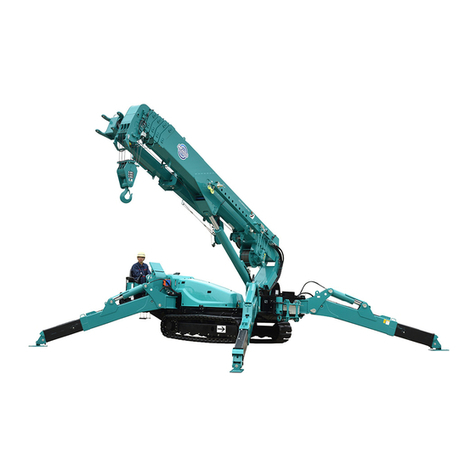
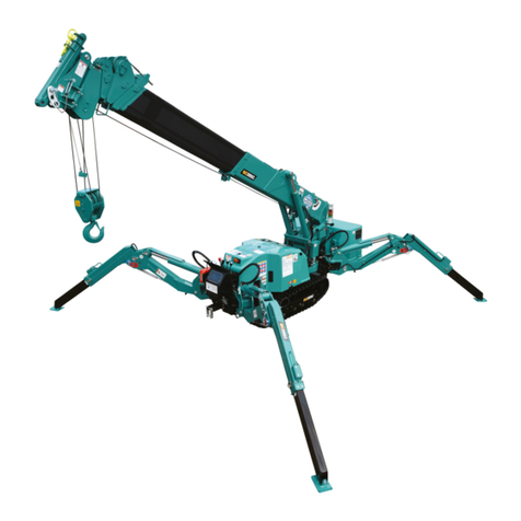
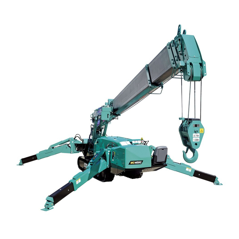
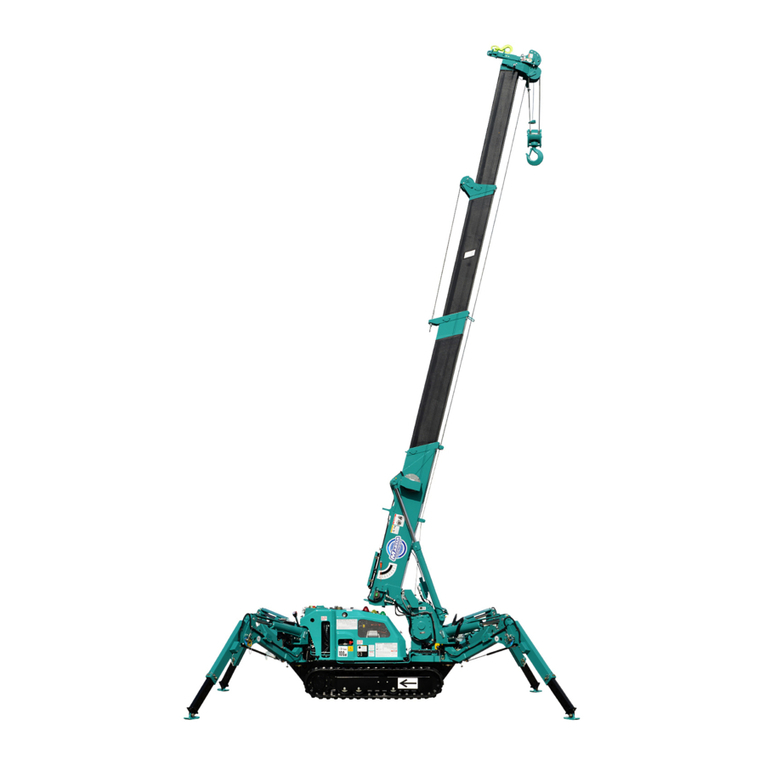
Maeda MC815C User guide

106E-QG1705-00
QUICK OPERATION GUIDE
CRAWLER CRANE
Serial No. T0001 and up
MC815C
・This operation guide explains basic operation of the machine. Before starting work, always
conduct checks written in “INSPECTION AND MAINTENANCE 9.1 PRE-OPERATION
INSPECTION” in the separate “OPERATION MANUAL”.
For safety cautions and detailed operation of the machine not explained in this book, please
read and understand the separate “OPERATION MANUAL” before operating this machine.
・This operation guide does not replace the operation manual. This is just a short helpful
information paper to assist the trained crane operator with the basic operation of the crane. For
complete and detailed information we refer to the operation manual of the crane.


- 1 -
CONTENTS
ITEM Page
1. DESCRIPTION OF CONTROLS 2
1.1 OUTRIGGER OPERATION PANEL 2
1.2 CONTROL LEVERS 3
2. DESCRIPTION OF MONITOR 4
3. OPERATIONS 8
3.1 STARTING / STOPPING ENGINE 8
3.2 TRAVELLING OPERATION 9
3.3 OUTRIGGER OPERATION 10
3.4 CRANE OPERATION 14
3.5 CRANE STOWAGE OPERATION 15
4. REMOTE CONTROL 17
4.1 STARTING / STOPPING ENGINE 17
4.2 TRAVELLING OPERATION 18
4.3 OUTRIGGER OPERATION 19
4.4 CRANE OPERATION 20
FOR SAFE USE OF THE MACHINE
This manual classifies the risks into the following three categories for easy understanding of the safety
information.
This denotes that there is an imminent hazard which will cause serious injury or
death.
It also provides information on how to avoid such hazard.
This denotes that there is a hazard which can cause serious injury or death.
It also provides information on how to avoid such hazard.
This denotes that there is a potential hazard which may cause minor or moderate
injury or serious damage to the machine.
It also provides information on how to avoid such hazard.
This manual also uses the following indications to provide other precautions for handling the machine and
helpful information.
This denotes that failure to properly handle the machine may damage it or shorten
its life.
This denotes helpful information.
CAUTION
NOTES

- 2 -
1. DESCRIPTION OF CONTROLS
(1) Outrigger operation panel
(2) Left control lever
(3) Right control lever
(4) Monitor
(5) Emergency stop switch
(6) Starter switch
(7) Lock lever
(8) Accelerator pedal
(9) Light switch
(10) Disconnect switch
(11) Override switch
(12) Fuse box
(13) Cigar socket
1.1 OUTRIGGER OPERATION PANEL
(1) Outrigger (1) switch
(2) Outrigger (2) switch
(3) Outrigger (3) switch
(4) Outrigger (4) switch

- 3 -
1.2 CONTROL LEVERS
[Traveling mode]
(1) Accelerator up/down
(pop-up up/down)
(2) Horn
(3) Pop-up Enter
(4) Mode selector switch
(Traveling Hi/Low)
(5) Mode selector switch
(Carry/Pick)
(6) Mode selector switch
(Traveling/Outrigger/
Crane)
(7) Right traveling forward
(8) Right traveling backward
(9) -
(10) -
(11) Left traveling forward
(12) Left traveling backward
(13) -
(14) -
[Outrigger mode]
(1) Accelerator up/down
(pop-up up/down)
(2) Horn
(3) Pop-up Enter
(4) Mode selector switch
(Extension/Ground)
(5) Mode selector switch
(Manual/Auto)
(6) Mode selector switch
(Traveling/Outrigger/
Crane)
(7) -
(8) -
(9) -
(10) -
(11) -
(12) -
(13) -
(14) -
[Crane mode]
(1) Accelerator up/down
(pop-up up/down)
(2) Horn
(3) Pop-up Enter
(4) Mode selector switch
(Crane Hi/Low)
(5) Mode selector switch
(Hook stowage/Fully
automated stowage)
(6) Mode selector switch
(Traveling/Outrigger/
Crane)
(7) Unwinding
(8) Winding
(9) Boom lowering
(10) Boom raising
(11) Boom extension
(12) Boom retraction
(13) Boom clockwise swing
(14) Boom counter-clockwise
swing

- 4 -
2. DESCRIPTION OF MONITOR
[ MONITOR DISPLAY (COMMON TO ALL MODES) ]
(1) Date & Time display
(2) Hour meter
(3) Engine speed
(4) Fuel gauge
(5) Eco mode switch
(6) DPF regeneration
switch
(7) Setting switch
(8) Engine and electric
motor switch
(9) Pop-up select switch
(up)
(10) Pop-up select switch
(down)
(11) Enter switch
(12) Replacement reminder
(13) Engine oil pressure
(14) Engine coolant
temperature
(15) Charge
(16) DPF regeneration
request lamp
(17) Exhaust temperature
alarm lamp
(18) DPF regeneration lamp
(19) Failure
(20) Emergency stop lamp
(21) Light
(22) Electricity on lamp
(23) Mode selector switch
(travel/outrigger/crane)
(24) Leveling instrument

- 5 -
[ MONITOR DISPLAY (TRAVELING MODE) ]
(1) BOOM LENGTH
(2) BOOM ANGLE
(3) WORKING RADIUS
(4) SLEW ANGLE
(5) RATED TOTAL LOAD
(6) ACTUAL LOAD
(7) LOAD CAPACITY
(8)MODE SELECTOR
SWITCH (2) (Traveling
Hi/Low)
(9)MODE SELECTOR
SWITCH (3) (Pick/Carry)
(10) FRONT VIEW CAMERA
MONITOR
(11)LEFT SIDE-VIEW
CAMERA MONITOR
(12)Error codes

- 6 -
[ MONITOR DISPLAY (OUTRIGGER MODE) ]
(1) Outrigger (1) Extension
(ANGLE SET-UP)
(2) Outrigger (2) Extension
(ANGLE SET-UP)
(3) Outrigger (3) Extension
(ANGLE SET-UP)
(4) Outrigger (4) Extension
(ANGLE SET-UP)
(5) Outrigger (1) (MIN)
(6) Outrigger (2) (MIN)
(7) Outrigger (3) (MIN)
(8) Outrigger (4) (MIN)
(9) Outrigger (1) (MID)
(10)Outrigger (2) (MID)
(11)Outrigger (3) (MID)
(12)Outrigger (4) (MID)
(13)Outrigger (1) (MAX)
(14)Outrigger (2) (MAX)
(15)Outrigger (3) (MAX)
(16)Outrigger (4) (MAX)
(17)Outrigger (1) (GROUND
SET-UP)
(18)Outrigger (2) (GROUND
SET-UP)
(19)Outrigger (3) (GROUND
SET-UP)
(20)Outrigger (4) (GROUND
SET-UP)
(21)Crane stow position
(22)Mode selector switch (2)
(Extension/Ground)
(23)Mode selector switch (3)
(Manual/Auto)
(24)Left side-view camera
monitor
(25)Error codes

- 7 -
[ MONITOR DISPLAY (CRANE MODE) ]
(1)Load capacity ratio indication
(2)Lifting height indication (LIFTING
HEIGHT)
(3)Lifting height limiter switch
(4)Boom angle upper limit switch
(5)Boom angle lower limit switch
(6)Working radius limiter switch
(7)Clockwise swing angle limiter switch
(8)Counter-clockwise swing angle limiter
switch
(9)Over un-winding indication (OVER
UN-WINDING)
(10)Hanging mode display
(N mode, P mode, M mode)
(11)Boom length indication (BOOM
LENGTH)
(12)Indication of the number of wires hung
(13)Over-winding indication (OVER
WINDING)
(14)Actual load indication (ACTUAL LOAD)
(15)Rated total load indication (RATED
TOTAL LOAD)
(16)Hook grounding indication (GROUND
CONTACT)
(17)Working radius indication (WORKING
RADIUS)
(18)Boom angle indication (BOOM
ANGLE)
(19)Slew angle indication
(20)Mode selector switch (3) (Hook
stowage/Fully automated stowage)
(21)Mode selector switch (2) (Crane
Hi/Low)
(22)Crane stowage position
(23)Outrigger related indication
(24)Error code

- 8 -
3. OPERATIONS
3.1 STARTING / STOPPING ENGINE
[ STARTING OF ENGINE ]
1. Insert the key into the starter switch, turn and hold the
key in the “ON” position, and wait until the “WARM-UP
MONITOR” indicator lamp goes out.
NOTES
When the starter switch key is turned to the “ON” position,
the “WARM-UP MONITOR” indicator lamp lights up to
indicate that the engine is being warmed up.
When the engine has been warmed up, the “WARM-UP
MONITOR” indicator lamp goes out.
2. When the “WARM-UP MONITOR” lamp goes out, turn the
key to the “START” position.
3. When the engine has started, release your hand from the
key.
The key automatically returns to the “ON” position.
[ STOPPING ENGINE ]
1. Take your foot off the accelerator pedal (6), let the engine
idle for about 5 minutes with no load applied.
2. Turn the starter switch key to the “OFF” position.
The engine stops.
3. Remove the starter switch key.

- 9 -
3.2 TRAVELLING OPERATION
1. Slowly and surely shift the lock lever (1) into a free (F)
position.
2. Change the mode to Travel with the mode selector switch
(1) (Travel/Outrigger/Crane) on the monitor, or with the
left control lever.
[ MOVING FORWARD ]
Operate the left and right control levers at the same time.
• Push the left and right control levers slowly forward to start
moving forward.
[ MOVING BACKWARD ]
Operate the left and right control levers at the same time.
• Pull the left and right control levers toward you slowly to
start moving backward.
[ LEFT TURN ]
Pushing the right control lever forward causes the machine
to turn left in the forward direction.
Pulling the right control lever toward you causes the machine
to turn left in the backward direction.
[ RIGHT TURN ]
Pushing the left control lever forward causes the machine to
turn right in the forward direction.
Pulling the left control lever toward you causes the machine
to turn right in the backward direction.
[ CHANGING TRAVELING SPEED MODE ]
Change the traveling mode with the mode selector switch (2)
(Traveling Hi/Low) on the monitor, or with the left control
lever.
• Each touch of the mode selector switch (2) (Traveling
Hi/Low) toggles the mode between “Traveling Hi” and
“Traveling Low”, and the monitor indication changes
accordingly.

- 10 -
3.3 OUTRIGGER OPERATION
[ OUTRIGGER SETTING OPERATION ]
TASKS TO BE PERFORMED BEFORE STARTING THE ENGINE
There are 4 outriggers installed on the machine.
The following explains the setting procedure for only one
“OUTRIGGER (4)”. Repeat the same procedure for the other
three outriggers.
1. Shift the lock lever (1) into the lock (L) position.
2. Turn the starter switch to the “ON” position.
3. Change the mode to Outrigger mode with the mode
selector switch (1) (Travel/Outrigger/Crane) on the
monitor or the left control lever.
4. Make sure that the crane stowage (1) lamp on the monitor
is lit in yellow.
5. Select the Manual mode with the mode selector switch (3)
(Manual/Auto) on the monitor or the left control lever.

- 11 -
6. Pull the position pin (1) out of the outrigger rotary (2) and
rotate the outrigger rotary outward.
7. Rotate the outrigger rotary (2) outwards so that it can
align with the pin hole, and insert the positioning pin (1)
into the hole as far as it will go.
NOTES
The positioning pin (1) is equipped with a wire to prevent
it from being lost.
8. Perform similar preparation work for the other 3
outriggers. NOTES
When you are finished with the above preparation steps
for other outriggers, check if the positioning pins (1) are
securely inserted in place.
9. Make sure that all of the four outrigger extension lamps
(2) on the monitor are lit in green.
NOTES
The crane stowage lamp (1) and four outrigger extension
lamps (2) on the monitor stay on.
OPERATIONS AFTER STARTING ENGINE
If the machine tilts at an angle of “3 degrees” or more while the outriggers are set, the
overturn warning buzzer sounds. Bring the machine to a horizontal position at which
the warning buzzer stops by operating the appropriate outrigger switches.
1. See “3.1 STARTING / STOPPING ENGINE” to start the
engine.
2. Slowly and surely shift the lock lever (1) into a free (F)
position.
3. Select the Extension mode with the mode select switch
(2) (Extension/Ground) on the monitor or the left control
lever.

- 12 -
4. Identify the outrigger to be operated by checking the
outrigger number shown on the operation nameplate
attached to each outrigger switch on the outrigger
operation panel.
5. Set two outrigger switches individually or simultaneously
to the “Extension” position.
When the inner boxes have reached the desired positions
respectively with the corresponding outrigger extension
cylinders extended, set the switch to the “NEUTRAL”
position.
Repeat the above steps for the other two switches to
extend all four outriggers to the desired positions, and set
the switches to the “NEUTRAL” position.
6. Select the Ground mode with the mode selector switch
(2) (Extension/Ground) on the monitor or the left control
lever.
7. Set two outrigger switches individually or simultaneously
to the “Extension” position.
When the adapters have touched the ground, with the
grounding cylinder extended, set the switch to the
“NEUTRAL” position temporarily.
Repeat the above steps for the other two switches to
allow all four outrigger adapters to come into contact with
the ground, and set the switches to the “NEUTRAL”
position.
When operating two outrigger switches at the same time, only two on the front side
(outriggers [(1)] and [(4)]) or two on the rear side (outriggers [(2)] and [(3)]) can be
operated at the same time. Simultaneous operation of the two switches for the
outriggers on either left or right side will cause the outriggers on one side to leave the
ground abruptly. This will result in overturning of the machine.

- 13 -
8. After all outrigger adapters have come into contact with
the ground, set two outrigger switches individually or
simultaneously to the “Extension” position.
When a grounding cylinder extends and the machine
slightly rises off the ground, set the switch to the
“NEUTRAL” position temporarily.
Repeat the above steps for the other two switches to
allow the four outriggers to raise the machine from the
ground at a constant height, and set the switches to the
“NEUTRAL” position temporarily.
Repeat the above steps to gradually raise the machine
from the ground so that the crawler belts can be situated
about 50 mm from the ground.
9. When the machine is raised up to a height of about
50 mm from the ground, adjust the machine so that
the machine is in a horizontal position while
checking the position of the yellow bubble in the
leveling instrument. At this point, if “automatic” is
selected for the mode selection switch (3), the
machine is automatically leveled so that it is in
horizontal condition.
10. When you are finished setting all outriggers, set all
outrigger switches to the “NEUTRAL” position.
11. Make sure that all of the four outrigger grounding lamps
(3) on the monitor are lit in green.
NOTES
All of the crane stowage lamp (1), the four outrigger
extension lamps (2) and four outrigger grounding lamps
(3) are lit in green.
CAUTION
If any of the outrigger grounding lamps (3) are
blinking red, remove the cover (7) of the outrigger
adapters (6) part and check them for foreign materials
being caught in the bend sections.
[ OUTRIGGER STOWING OPERATION ]
Reverse the outrigger set up procedure to stow the outrigger.

- 14 -
3.4 CRANE OPERATION
Perform the following operations before crane work.
1. Shift the lock lever (1) into the free (F) position.
2. Change the mode to Crane with the mode selector switch
(1) (Travel/Outrigger/Crane) on the monitor or the left
control lever.
[ HOOK RAISING AND LOWERING ]
Operate the right operation lever (1) as follows:
• Lowering: Push the lever forward.
• Neutral: Release your hand from the lever.
The lever will return to the “NEUTRAL” position
and the raising/lowering of the hook block stops.
• Raising: Pull the lever to the rear side.
[ BOOM DERRICKING OPERATION ]
Operate the right operation lever (1) as follows:
• Lower: Push the lever forward.
• Neutral:Release your hand from the lever.
The lever returns to the “NEUTRAL” position and
the boom derricking stops.
• Raise: Pull the lever to the rear side.
[ BOOM TELESCOPING OPERATION ]
Operate the left control lever (2) as follows:
• Extension: Push the lever forward.
• Neutral: Release your hand from the lever.
The lever returns to the “NEUTRAL” position
and the boom telescoping stops.
• Retraction: Pull the lever toward you.
[ SLEWING OPERATION ]
Operate the left control lever (2) as follows:
• Left slewing: Push the lever to the left.
• Neutral: Release your hand from the lever.
The lever returns to the “NEUTRAL” position
and the slewing stops.
• Right slewing:Push the lever to the right.

- 15 -
3.5 CRANE STOWAGE OPERATION
The hook stowage switch is used to cancel the automatic stop function of the over
winding detector.
Take sufficient care not to trap hands or objects when stowing the hook block.
CAUTION
• Before stowing the hook block, stop the hook block from swaying.
• When stowing the hook block, be careful not to allow the entire hook block to fall
sideways on the ground due to the wire rope being excessively loosened. Failure to
observe this may result in an irregular winding of the wire rope in the winch drum.
• The “Retract” operation of the boom will lower the hook block. The “Lowering”
operation of the boom also causes the hook block to move downward. Raise the hook
at the same time so that the hook block will not touch the ground or interfere with the
machine.
• Be sure to stow the boom in the designated position. After the boom has been stowed,
make sure that the crane stowage lamp on the monitor is lit in yellow. If the crane
stowage lamp is not lit in yellow, the outriggers cannot be stowed. If the crane
stowage lamp is not lit, perform operations, such as lowering the boom at the lowest
position, or slewing the boom, and check if the crane stowage lamp lights up in yellow.
[Manual stowage]
1. Pull the left control lever (2) toward you to retract the
boom completely.
2. Push and hold the left control lever (2) to the left or right
to slew the boom so that the slewing angle becomes 1 to
2 degrees.
If the boom angle is less than 20 degrees, the boom
cannot be slewed between 335 to 5 degrees to
prevent work directly above the operator.
3. Push and hold the right control lever (1) to the right until
the boom stops automatically.

- 16 -
4. Push the right control lever (1) forward, and hoist the
hook block until it automatically stops (over-winding is
detected). NOTES
If the hook block is excessively hoisted, the over hoist
detector is activated, generating an alarm buzzer. This
allows the ongoing winding operation to automatically
stop.
5. Change the mode change switch (3) to “Hook stowage”
on the monitor. While the button is pressed or the
screen is touched, the hook is hoisted automatically;
stow the hook (4).
6. Make sure that the crane stowage lamp (1) on the
monitor is lit in yellow.
NOTES
If the crane stowage lamp (1) is not lit in yellow, perform
again the said operation, fully retract and lower the boom,
or slew the boom.
[Automatic stowage]
When automatically stowing the crane, check that there are no interfering objects in the
surrounding area before doing so.
If you feel danger during automatic stowage, immediately stop the operation. Automatic
stowage can be stopped by pressing the emergency stop switch, or by operating the
monitor or crane.
1. When the fully automated stowage switch on the monitor is pressed once, the message
“Boom will be stowed. Make sure there is no obstacle around the boom.”will be displayed.
2. Pressing the fully automated stowage switch once more starts the automatic stowage
operation according to the following procedure.
(1) Hook is wound up until over-winding is detected.
(2) The boom is fully retracted.
(3) The boom is raised to 30 degrees.
(In case boom angle is below 30 degrees.)
(4) The boom is slewed to a 2 degree slewing angle.
(5) The boom is fully lowered.
(6) The hook is stowed.
This completes the automatic stowage.

- 17 -
4. REMOTE CONTROL
[ POWERING ON ]
1. Press the remote controller power ON/OFF switch (3)
once, and make sure that the power indicator on the
upper left corner of the left display blinks in green.
“Startsequenz eingeben” appears on the right display
when the remote controller is preparing to be powered
ON. NOTES
When the controller is ready for power-on, performing one
of the following operations will turn OFF the power to the
controller:
• Press and hold the remote controller power ON/OFF
switch (3).
• Aswitch other than the remote controller power ON/OFF
switch (3) is pressed.
• The controller has been left un-operated for 5 second or
longer.
2. When the controller is ready for power-on, pressing and
holding the remote controller power ON/OFF switch (3)
will change the display indication, allowing you to operate
the remote controller.
[ POWERING OFF ]
Press the Emergency stop/Remote controller power OFF
switch (10) when turning off the power to the transmitter, or
in case of an abnormality in crane operations.
The power of the Transmitter turns OFF and the engine
stops.
To cancel the emergency stop, turn the Emergency
stop/Remote controller power OFF switch (10) to the right.
The switch returns to the original position.
4.1 STARTING / STOPPING ENGINE
CAUTION
To start the engine, press and hold the engine
start/stop switch (4) until it starts.
[ STARTING THE ENGINE ]
Pressing the engine start/stop switch (4) when the engine is
stopped will allow the engine to start.
[ STOPPING THE ENGINE ]
Pressing the engine start/stop switch (4) when the engine is
running will allow the engine to stop.

- 18 -
4.2 TRAVELLING OPERATION
Set the operation mode selector switch (5) to Travel.
• Travel (red)
[ MOVING FORWARD ]
Operate the left and right control levers at the same time.
• Move forwards by slowly pushing the left operation lever (1)
and right operation lever (2) forwards.
[ MOVING BACKWARD ]
Operate the left and right control levers at the same time.
• Move backwards by slowly pulling the left operation lever
(1) and right operation level (2) towards yourself.
[ LEFT TURN ]
Pushing the right control lever (2) forward causes the
machine to turn left in the forward direction.
Pulling the right control lever (2) toward you causes the
machine to turn left in the backward direction.
[ RIGHT TURN ]
Pushing the left control lever (1) forward causes the machine
to turn right in the forward direction.
Pulling the left control lever (1) toward you causes the
machine to turn right in the backward direction.
[ CHANGING TRAVELING SPEED MODE ]
Only in the Crane and Travel modes, does it become
possible to switch the speed mode between High and Low by
pressing Speed selector/Outrigger select switch (6).
Other manuals for MC815C
2
Table of contents
Other Maeda Construction Equipment manuals

Maeda
Maeda CC423S-1 User manual

Maeda
Maeda MC405C-3 User manual

Maeda
Maeda CC1485S-1 User guide

Maeda
Maeda LC1385M-8BF User manual

Maeda
Maeda CC1485S-1 Installation manual

Maeda
Maeda MC-174CRM User manual

Maeda
Maeda CC1908S-1 User manual

Maeda
Maeda LC785M-6B User manual

Maeda
Maeda CC1908S-1 User manual

Maeda
Maeda MC405C-3 User manual

Maeda
Maeda CC1908S-1 User guide

Maeda
Maeda MC305C-3 User manual

Maeda
Maeda MC-174CRM User guide

Maeda
Maeda LC1385M-8B User manual

Maeda
Maeda MC815C User manual
Maeda
Maeda MC-104C-2 User manual

Maeda
Maeda MC-285C User guide

Maeda
Maeda LC785M-8B User manual

Maeda
Maeda MC174 User manual

Maeda
Maeda HIRD MC815 User manual