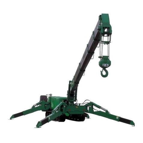
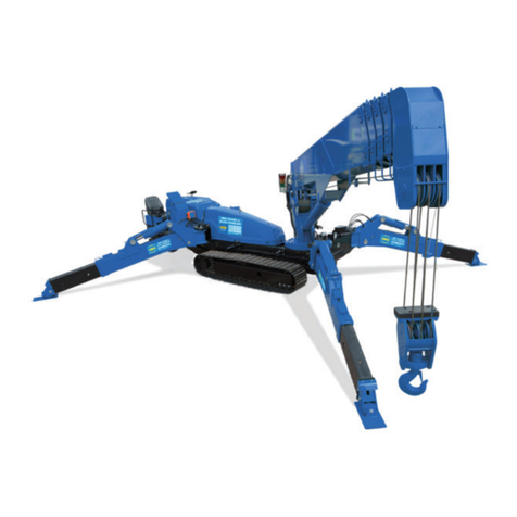
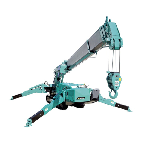
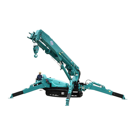
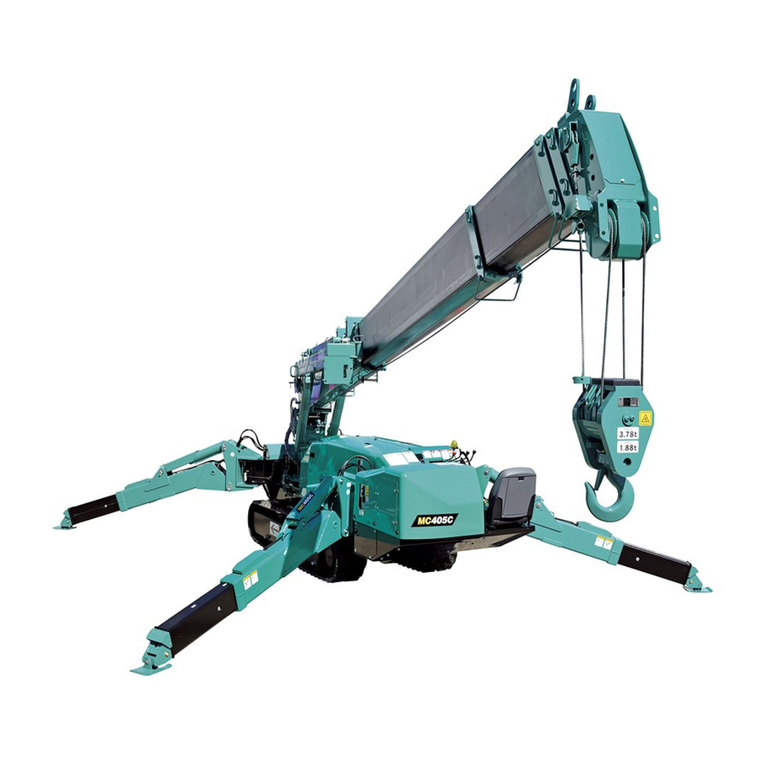
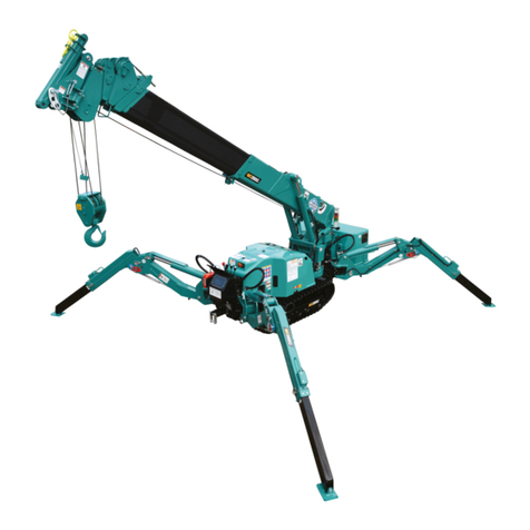
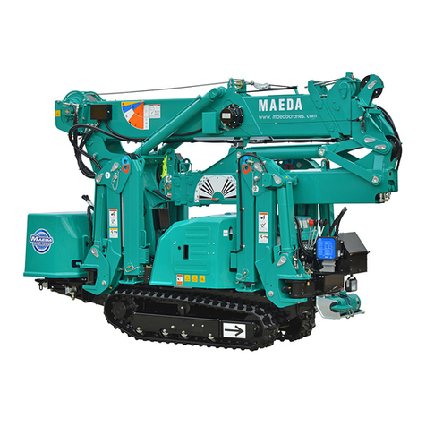
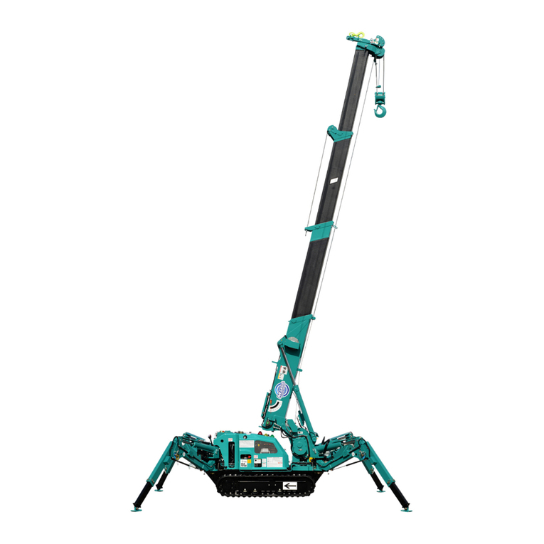
Maeda MC-174CRM User manual

101E-OM0906-00
OPERATION MANUAL
MINI-CRAWLER CRANE
Serial No. G0121and up
kWARNING
Unsafe use of this machine may cause serious injury or death. Operators
must read this manual before operating this machine. This manual should
be kept near the machine for reference and periodically reviewed by all
personnelwho willcome intocontact with it.
NOTICE
MAEDAhas Operation Manualwritten insome other languages. If a foreign
languagemanualisnecessary,contactyourlocaldistributorfor availability.


0-1
CONTENTS
ITEM
Page
INTRODUCTION
1- 1
1. INTRODUCTION
1- 2
2.FOR SAFE USE OF MACHINE
1- 3
3. MACHINE OVERVIEW
1- 4
3.1 SPECIFIED OPERATIONS
1- 4
3.2 MACHINE CONFIGURATION
1- 4
3.3 MACHINE FUNCTIONS
1- 5
4. QUALIFICATION FOR OPERATION
1- 6
4.1 QUALIFICATION FOR CRANE OPERATION
1- 6
5. TERMINOLOGY
1- 7
5.1 DEFINITION OF TERMS
1- 7
5.2 DIAGRAM OF WORKING RADIUS AND LIFTING HEIGHT
1- 8
5.3 TOTAL RATED LOAD CHART
1- 9
5.4 ANGLE INDICATOR
1-14
SAFETY
2- 1
1. BASIC PRECAUTIONS
2- 2
2. DRIVING RELATED PRECAUTIONS
2- 7
2.1 BEFORE STARTING THE ENGINE
2- 7
2.2 AFTER STARTING THE ENGINE
2- 8
2.3 WORKING WITH THE CRANE
2-12
3. TRANSPORT PRECAUTIONS
2-21
4. BATTERY HANDLING PRECAUTIONS
2-23
5. MAINTENANCE PRECAUTIONS
2-25
5.1 PRECAUTIONS BEFORE MAINTENANCE
2-25
5.2 PRECAUTIONS DURING MAINTENANCE
2-27
6. SAFETY LABEL LOCATIONS
2-32
7. WEEE DIRECTIVE LABEL LOCATIONS
2-39
OPERATION
3- 1
1. MACHINE BY SECTION
3- 2
1.1 MACHINE BY UNIT
3- 2
1.2 TRAVELLING OPERATION UNIT
3- 3
1.2.1 DESCRIPTION OF EACH LEVER
3- 4
1.2.2 DESCRIPTION OF EACH SWITCH
3- 6
1.2.3 DESCRIPTION OF EACH METER AND LAMP
3- 8
1.3 CRANE OPERATION UNITS
3- 9
1.3.1 DESCRIPTION OF EACH LEVER
3-10
1.3.2 DESCRIPTION OF EACH SWITCH
3-11
1.4 MOMENT LIMITER (OVERLOAD DETECTOR)
3-16
1.4.1 MOMENT LIMITER CONFIGURATION
3-16
1.4.2 FUNCTION OF MOMENT LIMITER
3-17
1.4.3 MOMENT LIMITER OPERATIONS
3-18

0-2
ITEM
Page
1.4.4 NAMES OF MOMENT LIMITER DISPLAY UNIT
3-20
1.4.5 OTHER MOMENT LIMITER FUNCTIONS
3-29
1.4.6 MOMENT LIMITER STARTING STATUS
3-30
1.4.7 MOMENT LIMITER ERROR CAUSES AND ACTIONS TO BE TAKEN
3-31
1.5 OVER HOIST DETECTOR
3-32
1.6 MACHINERY COVER
3-33
2. OPERATIONS
3-34
2.1 CHECKS BEFORE OPERATION
3-34
2.1.1 CHECKS BEFORE STARTING THE ENGINE (VISIBLE CHECKS)
3-34
2.1.2 CHECKS BEFORE STARTING THE ENGINE
3-37
2.1.3 CHECKS AFTER STARTING THE ENGINE
3-46
2.2 STARTING THE ENGINE
3-54
2.2.1 NORMAL ENGINE START
3-54
2.2.2 STARTING THE ENGINE WITH AUXILIARY STARTER SWITCH
3-56
2.2.3 STARTING THE ENGINE WITH RECOIL STARTER
3-58
2.3 OPERATIONS AND CHECKS AFTER STARTING THE ENGINE
3-59
2.4 BREAKING-IN MACHINE
3-61
2.5 MACHINE TRAVELLING POSITION
3-61
2.6 STARTING MOVING THE MACHINE
3-62
2.7 CHANGING MACHINE TRAVELLING MODE
3-63
2.8 CHANGING DIRECTION OF THE MACHINE
3-63
2.9 STOPPING/PARKING THE MACHINE
3-64
2.10 STOPPING THE ENGINE
3-65
2.11 INSPECTION AFTER STOPPING THE ENGINE
3-65
2.12 CAUTIONS WHILE DRIVING
3-66
2.13 OUTRIGGER SET UP OPERATION
3-68
2.13.1 NAME OF OUTRIGGER COMPONENTS
3-70
2.13.2 OUTRIGGER SET UP OPERATION
3-70
2.14 CAUTIONS BEFORE CRANE OPERATION
3-75
2.15 OPERATIONS BEFORE CRANE OPERATIONS
3-76
2.16 CRANE OPERATION POSITION
3-77
2.17 HOOK RAISING/LOWERING OPERATION
3-78
2.18 BOOM DERRICKING OPERATION
3-79
2.19 BOOM TELESCOPING OPERATION
3-80
2.20 SLEWING OPERATION
3-81
2.21 ACCELERATION OPERATION
3-82
2.22 CRANE STOWING OPERATION
3-83
2.23 OUTRIGGER STOWING OPERATION
3-85
2.24 DO’S AND DON’TS DURING CRANE OPERATIONS
3-91
3. HANDLING RUBBER TRACKS
3-93
3.1 GOOD USE
3-93
3.2 WARRANTY
3-93
3.3 PROHIBITIONS AND CAUTIONS WHEN USING RUBBER TRACKS
3-94
4. WHAT TO DO WITH TWISTED WINCH WIRE ROPE
3-97

0-3
ITEM
Page
5. TRANSPORTATION
3-98
5.1 LOADING/UNLOADING
3-98
5.2 HOISTING MACHINE
3-99
5.3 CAUTIONS IN LOADING MACHINE
3-100
5.4 CAUTIONS DURING TRANSPORTATION
3-100
6. HANDLING IN COLD WEATHER
3-101
6.1 PREPARING FOR LOW TEMPERATURE
3-101
7. LONG-TERM STORAGE
3-103
7.1 BEFORE STORING THE MACHINE
3-103
7.2 DURING STORAGE
3-103
7.3 AFTER STORAGE
3-103
8. HANDLING THE BATTERY
3-104
8.1 CAUTIONS IN HANDLING BATTERY
3-104
8.2 REMOVING/INSTALLING THE BATTERY
3-105
8.3 CAUTIONS WHEN CHARGING THE BATTERY
3-106
8.4 STARTING THE ENGINE WITH BOOSTER CABLE
3-107
9. TROUBLESHOOTING
3-109
9.1 ELECTRICAL COMPONENTS
3-109
9.2 MACHINE BODY
3-109
9.3 ENGINE
3-110
INSPECTION AND MAINTENANCE
4- 1
1. PRECAUTIONS FOR MAINTENANCE
4- 2
2. BASIC MAINTENANCE
4- 4
3. LEGAL INSPECTION
4- 6
4. CONSUMABLES
4- 6
5. LUBRICATING OIL
4- 7
5.1 USE OF LUBRICATING OIL ACCORDING TO TEMPERATURES
4- 7
6. ACCESSORY TOOLS AND STANDARD TIGHTENING TORQUE
4- 8
6.1 ACCESSORY TOOLS
4- 8
6.2 STANDARD TIGHTENING TORQUE LIST
4- 8
7. INSPECTION AND MAINTENANCE LIST
4-10
8. MAINTENANCE PROCEDURES
4-12
8.1 INITIAL 10 HOUR MAINTENANCE
4-12
8.2 INITIAL 25 HOUR MAINTENANCE
4-12
8.3 INITIAL 50 HOUR MAINTENANCE
4-12
8.4 INITIAL 200 HOUR MAINTENANCE
4-12
8.5 CHECKS BEFORE OPERATION
4-12
8.6 IRREGULAR MAINTENANCE
4-13
8.7 MAINTENANCE EVERY 50 HOURS
4-24
8.8 MAINTENANCE EVERY 100 HOURS
4-30
8.9 MAINTENANCE EVERY 250 HOURS
4-30
8.10 MAINTENANCE EVERY 500 HOURS
4-31
8.11 MAINTENANCE EVERY 1000 HOURS
4-33

0-4
ITEM
Page
SPECIFICATIONS
5- 1
1. SPECIFICATIONS
5- 2
2. OVERALL DIMENSIONS
5- 4
3. OUTRIGGER SPREAD DIMENSIONS
5- 5
4. RATED TOTAL LOAD CHART
5- 6
5. WORKING RANGE
5- 9
REMOTE CONTROL
6- 1
1. OUTLINE OF REMOTE CONTROLLER
6- 2
1.1 FEATURE
6- 2
1.2 CONFIGURATION
6- 2
1.3 FUNCTIONS OF REMOTE CONTROL SYSTEM
6- 3
2. SAFETY PRECAUTIONS
6- 4
2.1 FOR SAFETY OPERATIONS
6- 4
2.2 PRECAUTIONS FOR CRANE OPERATION
6- 6
2.2.1 PRIOR TO STARTING ENGINE
6- 6
2.2.2 SUBSEQUENT TO STARTING ENGINE
6- 7
2.2.3 TERMINATING THE OPERATION
6- 7
3. LOCATIONS OF SAFETY LABELS
6- 8
4. COMPONENTS OF THE TRANSMITTER
6-10
5. COMPONENTS OF THE RECEIVER
6-15
5.1 COMPONENTS OF THE RECEIVER
6-15
5.2 FUSE IN THE RECEIVER
6-17
6. MODE SETTING OF THE TRANSMITTER
6-18
6.1 A MODE
6-18
6.1.1 OPENING A MODE SCREEN
6-18
6.1.2 MESSAGES IN THE A MODE SCREEN
6-18
6.1.3 AN EXAMPLE FOR SETTING IN THE A MODE
6-22
6.2 PROCEDURE IN THE OPERATION MODE
6-23
6.2.1 CALL OUT CRANE MODE
6-23
6.2.2 CALL OUT OUTRIGGER MODE
6-24
7. CHECKING BEFORE OPERATION
6-26
7.1 CHECKING BEFORE STARTING ENGINE
6-26
7.1.1 CHECKING BEFORE TURNING ON THE TRANSMITTER
6-26
7.1.2 CHECKING AFTER TURNING ON THE TRANSMITTER
6-27
7.1.3 CHECKING RECEIVER
6-31
7.2 CHECKING AFTER STARTING ENGINE
6-32
7.2.1 VERIFICATION FOR THE ENGINE START AND STOP
6-32
7.2.2 CHECKING “OUTRIGGER MODE”OPERATION
6-33
7.2.3 CHECKING “CRANE MODE”OPERATION
6-35
8. OPERATION
6-38
8.1 CAUTIONS BEFORE OPERATION
6-38
8.2 OPERATION IN OUTRIGGER MODE
6-39
8.2.1 OUTRIGGER SETTING
6-41
8.2.2 OUTRIGGER STOWING
6-43

0-5
ITEM
Page
8.3 OPERATION IN CRANE MODE
6-44
8.3.1 SLEWING OPERATION
6-46
8.3.2 BOOM TELESCOPING
6-46
8.3.3 HOOK RAISING AND LOWERING
6-47
8.3.4 BOOM DERRICKING
6-47
8.3.5 SET-UP AND CANCEL MICRO SPEED
6-48
8.3.6 ENGINE STOP AND EMERGENCY STOP PROCEDURE
6-50
8.3.7 ENGINE START AND RESET PROCEDURE
6-50
8.4 CHECKING AFTER CRANE OPERATION
6-51
9. TROUBLE SHOOTING
6-52
9.1 BEFORE TROUBLE SHOOTING
6-52
9.2 ERRORS IN THE REMOTE CONTROL DEVICES
6-53
10. SYSTEM SPECIFICATIONS
6-55

0-6

1-1
INTRODUCTION
1. INTRODUCTION
1- 2
2.FOR SAFE USE OF MACHINE
1- 3
3. MACHINE OVERVIEW
1- 4
4. QUALIFICATION FOR OPERATION
1- 6
5. TERMINOLOGY
1- 7

1-2
1. INTRODUCTION
Thank you for purchasing our Mini Crawler Crane “MC-174CRM”.
This manual is a guidebook for the safe and effective use of this machine.
This manual describesthe procedures for proper operation and maintenance of the machine.
Warnings and precautions defined in this manual must be observed for safety.
Accidents are caused when operation, inspection, or maintenance is not followed according
to these guidelines.
Be sure to read this manual and understand the procedures for machine operation,
inspection, and maintenance thoroughly before operating this machine.
Failure to observe the basic precautions defined in this manual may lead to hazardous
accidents.
Failure to use this machine properly can lead to serious personal injury or death.
Operators and maintenance personnel must always read this manual prior to
operation or maintenance of this machine.
Save this manual at a designated place for reference when necessary. All personnel
who work on this machine are to carry out periodic reference.
•Only those who have a thorough understanding of the fundamental procedures
provided in this manual are qualified to perform machine operation.
•Keep this manual handy for reference when necessary.
•Should you lose or damage this manual, contact Maeda or our sales service
agency immediately for ordering a new manual.
•This manual should always accompany this machine upon transfer of the machine
to the next owner.
•This manual has adopted data that was available at the time of the creation of the
manual.
The contents of this manual, including maintenance specifications, tightening
torque, pressure, measuring method, adjustment value, and illustrations, are
subject to change upon unremitting refinement of the machine, without notice.
Machine maintenance may be susceptible to revisions. Always obtain the latest
information from Maeda or our sales service agency before performing
maintenance of this machine.
For safety instructions, see “2. For Safe Use of Machine” on page 1-3 and “Safety”
on page 2-1.

1-3
2. FOR SAFE USE OF MACHINE
This manual classifies the risks into the following three categories to present the details of the safety
labels in easy-to-understand manner.
This denotes that there is an imminent hazard which will cause serious
personal injury or death.
Follow instructions to avoid danger.
This denotes that there is a hazard which can cause serious personal injury
or death.
Follow instructions to avoid danger.
This denotes that there is a potential hazard which may cause minor or
moderate personal injury or serious damage to this machine.
Follow instructions to avoid danger.
This manual also provides the following to indicate what must be observed for the sake of the machine
and what will be of help.
This denotes that failure to handle the machine properly may damage the
machine or shorten its life.
This denotes helpful information.
This manual covers not only procedures for operation, inspection, and maintenance of this machine, but
also safety precautions where this machine is only used for specified tasks.
Not every event is foreseeable and therefore, cautions given in this manual and on this machine do not
necessarily cover every safety-related issue.
The result of operation, inspection, and maintenance carried out in a way that is not described in this
manual are your responsibility.
Even in the above case, never attempt any work or operation that this manual prohibits you to do.
CAUTION
NOTES

1-4
3. MACHINE OVERVIEW
3.1 SPECIFIED OPERATIONS
This machine is to be used for operation listed below.
•Crane operation
This machine is a mobile crane with a rubber track travelling dolly (carrier) mounted with a boom crane.
This self-propelled crane is capable of moving (travelling) in the worksite and craning an object weighing
within the rated total load.
This is also a remote-controlled crane.
3.2 MACHINE CONFIGURATION
(1) Travelling dolly
(2) Crane
(3) Safety device
Viewed from the operator’s seat, the front, back, left, and right of the
machine are determined in this manual, viewing in the travelling
direction (front) of the machine.
Boom slewing motion is determined with the machine viewed from
immediately above; slew clockwise denotes right-handed motion and
slew counterclockwise denotes left-handed motion.
EXTERNAL VIEW

1-5
This machine is composed of the units listed below.
[1] TRAVELLING DOLLY
This is composed of a travelling gear, engine, travelling operation unit, and crane operation unit.
[2] CRANE
This is composed of a telescoping system, derrick system, hook block, winch system, and outrigger
system.
[3] SAFETY DEVICE
This is composed of the following parts and devices: Over hoist detector/automatic stop device, angle
indicator, hydraulic safety valve, hydraulic automatic locking device, slinging rope detachment protector,
alarm buzzer, audio alarm,level, crane tip-over alarm (an alarmissued in the event of the crane operation
at 3-degree inclination and travelling at 15-degree inclination), travelling lever lock, travelling/crane
selector switch (designed to prevent the machine from craning at travelling), moment limiter (working
envelope limited), working status lamp.
3.3 MACHINE FUNCTIONS
[1] TRAVELLING DOLLY
•This is a compact machine designed to keep the overall width between the crane and outrigger
minimized with them housed (in travelling position).
This compact design is ideal for work in confined areas.
•Two-travelling lever operation enables not only direction changes among forward, backward, and
right/left but pivot turn and spin turn.
[2] CRANE
•An automatic slide outrigger is included in the crane to permit outrigger extension and grounding from
the operator’s station.
•Through the combined use of telescoping, derricking, slewing, and winch system operation, the crane is
capable of raising or lowering the hook block and moving an object weighing within the rated total load
to a designated position within the confines of the working envelope.
•Remote-control units allow remote outrigger setting and remote crane operation.

1-6
4. QUALIFICATION FOR OPERATION
•A high incidence of occupational accidents in crane operation has been reported.
Be aware that experienced engineers are also no exception.
•Warnings and precautions defined in this manual shall be observed for safety assurance
during operation of the machine.
4.1 QUALIFICATION FOR CRANE OPERATION
Only personnel that have obtained the correct training or license stipulated by laws and regulations
applicable to the place of use are qualified to operate this machine.
Contact the relevant government office or our sales service agency for further information.

1-7
5. TERMINOLOGY
5.1 DEFINITION OF TERMS
[1] RATED TOTAL LOAD
This is the maximum load that can be applied according to a boom
length and angle. The load includes the mass (weight) of hoisting
accessories (hooks) and slinging ropes.
[2] RATED LOAD
This is a load derived by subtracting the mass (weight) of hoisting
accessories (hooks) and slinging ropes from the rated total load,
which is a withstand load for hoisting.
[3] WORKING RADIUS
This is a horizontal distance between the axis of slewing and the
hook center.
[4] BOOM LENGTH
This is a distance between the boom primary pin and the sheave
pin of the end boom.
[5] BOOM ANGLE
This is an angle which the boom forms with the horizontal plain.
[6] LIFTING HEIGHT ABOVE GROUND
This is a vertical distance between the hook bottom and the ground
with the hook raised to the upper limit.

1-8
5.2 DIAGRAM OF WORKING RADIUS AND LIFTING HEIGHT
•The diagram of working radius and lifting height shows the relationships between the working
radius of this machine, boom angle, and lifting height above the ground with no object
hoisted. The diagram has been made allowing for no deflection in the boom.
•The boom (4) in the diagram of working radius and lifting height represents a state that half of
the “
mark”passes boom (3).
1. Point A denotes a boom angle and point B denotes a lifting
height above ground in the figure at right.
The same working radius is applied to points A and B.
2. The “diagram of working radius and lifting height” shows the
relationships the working radius, boom angle, and lifting
height at no load, allowing for no deflection in the boom.
A deflection occurs in the boom when an object is hoisted,
which causes the working radius to widen slightly.
The rated total load decreases with increase in the working
radius.Actual crane operation requires theplanning of work,
allowing for sufficient clearance more than that provided in
the diagram.

1-9
5.3 TOTAL RATED LOAD CHART
•All the values provided in the total rated load chart are based on the assumption that the
machine is placed on a level and firm surface.
The machine may topple over if proper outrigger setting or ground condition fails to be
assured. Exercise due caution when performing crane operation.
•The values in the total rated load chart are determined based on the working radius allowing
for deflection that is developed when load is applied to the boom.
•When extending 3rd boom even if only slightly, crane operation should proceed to the extent
of performance of “4.21mBoom”.
•When half of the “
mark” passes 2nd boom, crane operation should proceed to the extent of
performance of “5.45m Boom”.
•If the working radius exceeds that stated in the table even if only slightly, crane operation
should proceed with respect to the rated total load corresponding to the working radius in the
following table.
•The rated total load is a load including the mass of a hoisting accessory (hook: 20kg).
•When the crane is used with the outriggers extended other than at the maximum, crane
operation should proceed with respect to the values specified in the total rated load chart
corresponding to Rated Total Load Chart with outrigger extended to other than Maximum.

1-10
The total rated load chart provides the maximum loads that the crane is capable of hoisting objects in
parallel with the length of the boom. The loads are specified by working radius.
[1] BOOM LENGTH
The following figures illustrate the condition of the booms, “1.83m Boom”, “2.97m Boom”, “4.21m Boom”
and “5.45m Boom”in the preceding boxes in the total rated load chart.
1. “1.83m Boom”: All the booms are retracted.
2. “2.97m Boom”: With booms (3) and (4) retracted, boom (2) is fully extended.
“2.97m Boom”is to apply to crane operation with boom (2) extended even if only slightly.
3. “4.21m Boom”: With booms (2) fully extended, booms (3) and (4) are extended midway (half of the “
mark” passes boom (2)).
“4.21m Boom”is to apply to crane operation with booms (3) and (4) extended even if only slightly.

1-11
4. “5.45m Boom”: All the booms are fully extended.
“5.45m Boom”is to apply to crane operation with half of the “
mark” on boom (3) passes boom (2).

1-12
[2] OUTRIGGER MAXIMUM EXTENSION
•Make sure all the outriggers are placed in the correct position before performing crane
operation.
It is strictly forbidden to perform any crane operation before you place outriggers.
•Always place the machine in a horizontal position with the use of the level when extending the
outriggers. A warning buzzer sounds when the machine is inclined 3° or more and stops when
the machine is placed in a horizontal position.
•Where a crane operation in a condition that outriggers are not fully extended is required, see "
Rated Total Load Chart with outrigger extended to other than Maximum" of the Rated Total
Load Chart. Failure to perform crane operation with proper values may cause the machine to
topple over. Exercise caution when performing operation.
•Despite the maximum extension of all the outriggers, the
width of extended outriggers decreases due to an
ungraded ground even when clearance "a" in the right
figure is 50 mm. Crane operation should proceed with
respect to the values specified in “When the crane is
used with the outriggers extended midway”in the total
rated load chart.
•Where any of the outrigger inner box is retracted into the
outer box, only " Rated Total Load Chart with outrigger
extended to other than Maximum " of the Rated Total
Load Chart is applicable for that crane operation, even
when it is retracted for the length of 1 position pin span.
•The machine becomes unsteady at some point if it undergoes a 360-degree slewing with an
object hoisted. Irrespective of the rated total load, ensure operation is in a short working
radius and at low speed.
The diagram shown on the right represents the condition “When
the crane is used with the outriggers extended at the maximum” in
the total rated load chart.
If the inner box is retracted even if only slightly, crane operation
should proceed with respect to the values specified in the total
rated load chart corresponding to “Rated Total Load Chart with
outrigger extended to other than Maximum”.
See "OPERATION 2.13 OUTRIGGER SET UP OPERATION”for
proper setting of the outriggers.
NOTES
Outrigger maximum extension is defined as that:
1. The outrigger is set at the positioning pin position (55 degrees
front, 50 degrees back).
2. The inner box of all the outriggers is extended fully.
3. All the outriggers are placed on a level surface.
4. Approx. 50mm is assured for clearance "a” (between the
outrigger bottom and crawler bottom) as shown in the figure to
the right.
Other manuals for MC-174CRM
2
Table of contents
Other Maeda Construction Equipment manuals

Maeda
Maeda MK1033C-1 User manual

Maeda
Maeda MC815C User manual

Maeda
Maeda MC174 User manual

Maeda
Maeda LC1385M-8BF User manual

Maeda
Maeda MC285C-3 User manual

Maeda
Maeda LC785M-6B User manual

Maeda
Maeda MC-305C-2 User manual

Maeda
Maeda MC-285C User guide

Maeda
Maeda CC1908S-1 User guide

Maeda
Maeda CC1485S-1 Installation manual

Maeda
Maeda MC-104C-2 User manual

Maeda
Maeda MC-174CRM User manual

Maeda
Maeda CC1908S-1 User manual

Maeda
Maeda MC815C User manual

Maeda
Maeda MC-305C-2 User manual

Maeda
Maeda MC285C-3 User manual

Maeda
Maeda LC785M-8B User manual

Maeda
Maeda CC1908S-1 User manual

Maeda
Maeda CC1485S-1 User guide

Maeda
Maeda MC815C User guide