Maeda CC1485S-1 Installation manual

585E-OM1712-02
OPERATION MANUAL
CRAWLER CRANE
Serial No. 7048 and up
Unsafe use of this machine may cause serious injury or death. Operators
must read this manual before operating this machine. This manual should
be kept near the machine for reference and periodically reviewed by all
personnel who will come into contact with it.
NOTICE
MAEDA has Operation Manuals written in some other languages. If a
foreign language manual is necessary, contact your local distributor for
availability.
CC1485S
-1


i
CONTENTS
Item
Page
INTRODUCTION
1
1. INTRODUCTION 2
2. FOR SAFE USE OF THE MACHINE 3
3. MACHINE OVERVIEW 4
3.1 SPECIFIED OPERATIONS
4
3.2 MACHINE STRUCTURE 4
3.3 MACHINE FUNCTIONS
5
4. QUALIFICATION FOR OPERATION 6
4.1 QUALIFICATION FOR CRANE OPERATION 6
5. CRANETERMINOLOGY 7
5.1 TERMS AND DEFINITIONS 7
5.2 DIAGRAM OF WORKING RADIUS AND LIFTING HEIGHT
8
5.3 RATED TOTAL LOAD CHART 9
SAFETY
13
1. BASIC PRECAUTIONS 14
1.1 PRECAUTIONS BEFORE STARTING WORK 14
1.2 PREPARING FOR SAFE OPERATION 15
1.3 PRECAUTIONS FOR FIRE PREVENTION 17
1.4 CAUTIONS IN GETTING ON AND OFF THE MACHINE 18
1.5 OTHER PRECAUTIONS
19
2. OPERATION RELATED PRECAUTIONS 20
2.1 PRECAUTIONS ON WORK SITE
20
2.2 CAUTIONS WHEN STARTING ENGINE 23
2.3 PRECAUTIONS FOR STARTING CARRIER AND OPERATING CRANE 25
2.4 CAUTIONS DURING CRANE OPERATION 29
3. TRANSPORT PRECAUTIONS 37
4. MAINTENANCE PRECAUTIONS
39
4.1 PRECAUTIONS BEFORE MAINTENANCE 39
4.2 PRECAUTIONS DURING MAINTENANCE 43
5. SAFETY LABEL LOCATIONS
48

ii
Item
Page
OPERATION
59
1. NAME OF EACH SECTION 60
1.1 MACHINE UNITS
60
1.2 CRANE OPERATION UNITS 61
1.2.1 MACHINE MONITOR COMPONENTS 62
2. EXPLANATION OF ALL EQUIPMENT 63
2.1 MACHINE MONITOR 63
2.1.1 MONITOR BASIC ACTION AND DISPLAY
65
2.1.2 WARNING DISPLAY 72
2.2 SWITCHES 75
2.3 OPERATION LEVERS AND PEDALS 85
2.4 MOMENT LIMITER (OVERLOAD PREVENTIVE DEVICE) 89
2.4.1 CONFIGURATION OF MOMENT LIMITER 89
2.4.2 FUNCTIONS OF MOMENT LIMITER 90
2.4.3 MOMENT LIMITER OPERATION AND CANCELING (RECOVERY) 91
2.4.4 MOMENT LIMITER FUNCTIONS 94
2.4.5 MOMENT LIMITER CANCELING SWITCH 102
2.5 OVERWINDING PREVENTION DEVICE
104
2.6 AIR CONDITIONER HANDLING 105
2.6.1 COMPONENTS OF CONTROL PANEL 105
2.6.2 AIR CONDITIONER OPERATION METHOD 109
2.6.3 PRECAUTIONS IN AIR CONDITIONER USE 111
2.6.4 INSPECTION AND MAINTENANCE OF AIR CONDITIONER INSTALLED ON
THE MACHINE
111
2.7 CAR RADIO HANDLING
112
2.7.1 EXPLANATION OF THE EQUIPMENT 112
2.7.2 CAR RADIO OPERATION METHOD
115
2.7.3 PRECAUTIONS IN CAR RADIO USE 117
2.8 FUSE 118
2.9 FUSIBLE LINK
119
2.10 CONTROLLER 120
2.11 CAB FRONT WINDOW
121
2.12 DOOR 123
2.13 HAMMER FOR EMERGENCY ESCAPE 124
2.14 CAP AND COVER WITH LOCK 125
2.15 BATTERY ROOM DOOR 126
2.16 LEFT COVER
126
2.17 RIGHT COVER 127
2.18 MACHINERY COVER 128
2.19 HOLDER FOR OPERATION MANUAL
128
2.20 GREASE PUMP HOLDER 129
2.21 CUP HOLDER
129
2.22 RETRACTABLE SEAT BELT HANDLING 129

iii
Item
Page
3. OPERATION
130
3.1 PRE-OPERATION INSPECTION 130
3.1.1 CHECKING BEFORE STARTING ENGINE
130
3.1.2 CHECKING BEFORE STARTING ENGINE 133
3.1.3 CHECKING AFTER STARTING ENGINE 147
3.2 OPERATIONS AND CHECKS BEFORE STARTING ENGINE 150
3.3 STARTING ENGINE 151
3.4 OPERATIONS AND CHECKS AFTER STARTING ENGINE
153
3.4.1 WARM-UP OPERATIONS FOR ENGINE 153
3.4.2 WARM-UP OPERATIONS FOR HYDRAULIC EQUIPMENT 154
3.5 STOPPING ENGINE 156
3.6 BREAK-IN OPERATION 157
3.7 MACHINE TRAVELLING POSTURE 157
3.8 STARTING (FORWARD AND BACKWARD)/STOPPING THE MACHINE 158
3.9 CHANGING DIRECTION OF THE MACHINE 161
3.10 SLEWING THE MACHINE 162
3.11 PARKING THE MACHINE 163
3.12 INSPECTION AND CHECK AFTER COMPLETING WORK
164
3.12.1 AFTER STOPPING ENGINE 164
3.12.2 LOCKING 164
3.13 CAUTIONS IN DRIVING 165
3.14 PRECAUTIONS BEFORE CRANE OPERATION 168
3.15 OPERATION BEFORE CRANE WORK
170
3.16 CRANE OPERATION POSTURE 172
3.17 HOISTING AND LOWERING OPERATION 173
3.17.1 NORMAL HOISTING AND LOWERING OPERATION 173
3.17.2 HOISTING AND LOWERING OPERATION AT HIGH SPEED 174
3.17.3 HOISTING OPERATION WITH HOOK STOWAGE SWITCH 175
3.18 BOOM DERRICKING OPERATION 176
3.19 BOOM TELESCOPING OPERATION 177
3.20 SLEWING OPERATION
179
3.21 ACCELERATOR OPERATION 180
3.22 CRANE STOWAGE OPERATION
182
3.22.1 CRANE STOWAGE OPERATION AT THE TIME OF SIMPLE STOWAGE OF
HOOK BLOCK
182
3.22.2 CRANE STOWAGE OPERATION AT THE TIME OF NORMAL STOWAGE OF
HOOK BLOCK
185
3.23 PROHIBITED OPERATIONS DURING CRANE WORK 187
3.24 OPERATION DURING TRAVELLING HOIST 189
3.24.1 PRECAUTIONS IN OPERATION DURING TRAVELLING HOIST
189
3.24.2 OPERATION POSTURE DURING TRAVELLING A HOISTED LOAD 190
3.24.3 OPERATION OF TRAVELLING A HOISTED LOAD WORK
191
3.24.4 CANCEL OPERATION OF TRAVELLING HOIST OPERATION POSTURE 191

iv
Item
Page
4. HANDLING OF WIRE ROPE 192
4.1 CRITERIA FOR WIRE ROPE REPLACEMENT
192
4.2 WINCH WIRE ROPE REEVING SYSTEM AND GROSS RATED LOAD 194
4.3 MEASURE TO TAKE WHEN WINCH WIRE ROPE IS TWISTED
195
5. TRANSPORTATION 197
5.1 LOADING/UNLOADING 197
5.1.1 LOADING 198
5.1.2 FIXING THE MACHINE 200
5.1.3 UNLOADING
201
5.2 HOISTING MACHINE 202
5.2.1 HOISTING MACHINE WITH BOOM LOWERED 202
5.2.2 HOISTING MACHINE WITH BOOM 204
5.3 CAUTIONS DURING TRANSPORTATION 205
6. HANDLING WHEN COLD
206
6.1 PREPARING FOR LOW TEMPERATURE 206
7. LONG-TERM STORAGE 208
7.1 BEFORE STORING MACHINE
208
7.2 DURING STORAGE 208
7.3 AFTER STORAGE
209
8. TROUBLESHOOTING 210
8.1 WHEN FUEL RUNS OUT 210
8.2 PHENOMENONS THAT ARE NOT A FAULT
211
8.3 WHEN BATTERY HAS DISCHARGED 212
8.3.1 BATTERY HANDLING PRECAUTIONS
212
8.3.2 REMOVING/INSTALLING BATTERY 213
8.3.3 CAUTIONS IN CHARGING BATTERY 214
8.3.4 STARTING ENGINE WITH BOOSTER CABLE 215
8.4 WHEN SUCH A PHENOMENON OCCURS 217
8.4.1 ELECTRICAL COMPONENTS
217
8.4.2 MACHINE BODY COMPONENTS 219
8.4.3 ENGINE COMPONENTS 220
8.4.4 MOMENT LIMITER COMPONENTS
222
8.4.5 OVERWINDING PREVENTION DEVICE 223

v
Item
Page
INSPECTION AND MAINTENANCE
225
1. PRECAUTIONS FOR MAINTENANCE 226
2. BASIC MAINTENANCE
228
3. LEGAL INSPECTION 232
4. PERIODIC REPLACEMENT OF CRITICAL PARTS 233
5. CONSUMABLES 234
6. OTHER REPLACEMENT PARTS 235
7. USE OF FUEL AND LUBRICATING OIL
236
7.1 USE OF FUEL AND LUBRICATING OIL ACCORDING TO TEMPERATURES 236
8. STANDARD TIGHTENING TORQUE 238
8.1 STANDARD TIGHTENING TORQUE LIST 238
9. LIST OF ITEMS FOR INSPECTION AND MAINTENANCE 239
10. MAINTENANCE PROCEDURES 241
10.1 INITIAL 500 HOUR MAINTENANCE 241
10.2 PRE-OPERATION INSPECTION 241
10.3 IRREGULAR MAINTENANCE 242
10.4 MAINTENANCE EVERY 50 HOURS 258
10.5 MAINTENANCE EVERY 250 HOURS
260
10.6 MAINTENANCE EVERY 500 HOURS 264
10.7 MAINTENANCE EVERY 1000 HOURS 274
10.8 MAINTENANCE EVERY 1500 HOURS 279
10.9 MAINTENANCE EVERY 3000 HOURS 279
10.10 MAINTENANCE EVERY 4000 HOURS
280
10.11 MAINTENANCE EVERY 5000 HOURS 281
11. VENTING AIR IN HYDRAULIC CIRCUITS 284
12. RELIEVING INTERNAL PRESSURE OF HYDRAULIC CIRCUIT 288
13. ATTACHING/DETACHING SINGLE-FALL HOOK 289
13.1 ATTACHING SINGLE-FALL HOOK 289
13.2 DETACHING SINGLE-FALL HOOK 292
SPECIFICATIONS
295
1. PRINCIPLE SPECIFICATION LIST
296
2. SPECIFICATION DIMENSIONAL DRAWING 297
3. RATED TOTAL LOAD CHART
298
4. WORKING RADIUS/LIFTING HEIGHT 301

vi
Item
Page
FLY-JIB
303
1. PRECAUTIONS OF FLY-JIB OPERATION 304
2. SAFETY LABEL LOCATION
306
3. FLY-JIB EACH SECTION 309
4. FLY-JIB INSTALLATION AND STOWAGE 310
4.1 INSTALLATION OF FLY-JIB 311
4.2 CHANGING OF FLY-JIB TILT ANGLE 316
4.3 EXTENDING AND RETRACTING NO.2 FLY-JIB
321
4.3.1 EXTENDING NO.2 FLY-JIB CONFIGURED 0 DEGREE OR 20 DEGREES
TILT ANGLE
321
4.3.2 EXTENDING NO.2 FLY-JIB CONFIGURED 40 DEGREES OR 60 DEGREES
TILT ANGLE
322
4.3.3 RETRACTING OF No.2 FLY-JIB 324
4.4 STOWAGE OF FLY-JIB 325
4.5 REMOVAL OF FLY-JIB 330
4.6 INSTALLATION OF FLY-JIB 334
5. HANDLING MONITOR AND MOMENT LIMITER
342
5.1 NAMES OF MONITOR DISPLAY 342
5.1.1 MONITOR DISPLAY IN FLY-JIB MODE 342
5.1.2 MONITOR DISPLAY WHEN FLY-JIB IS STOWED 344
5.2 MOMENT LIMITER FUNCTIONS 345
5.2.1 DISPLAY FOR FLY-JIB MODE SWITCHING 346
5.3 SETTING OF OPERATING CONDITIONS 347
6. OPERATIONS 348
6.1 CAUTIONS FOR FLY-JIB OPERATION 348
7. TROUBLESHOOTING 349
7.1 LIST OF ERROR CODES
349
7.2 WHEN SUCH A PHENOMENON OCCURS 350
8. INSPECTION AND MAINTENANCE 351
8.1 CHECKING BEFORE OPERATION 351
8.2 MAINTENANCE EVERY 50 HOURS 353
9. SPECIFICATIONS
354
9.1 SPECIFICATION TABLE 354
9.2 SPECIFICATION DIMENSIONAL DRAWING 355
9.3 RATED TOTAL LOAD CHART 356
9.4 WORKING RADIUS/LIFTING HEIGHT 357
9.4.1 WORKING RADIUS/LIFTING HEIGHT (WHEN FLY-JIB ANGLE IS 0 DEGREES
AND 20 DEGREES)
357
9.4.2 WORKING RADIUS/LIFTING HEIGHT (WHEN FLY-JIB ANGLE IS 40 DEGREES
AND 60 DEGREES)
358

1
INTRODUCTION
1. INTRODUCTION 2
2. FOR SAFE USE OF THE MACHINE
3
3. MACHINE OVERVIEW
4
4. QUALIFICATION FOR OPERATION 6
5. CRANE TERMINOLOGY 7

2
1. INTRODUCTION
Thank you for purchasing Maeda Crawler Crane CC1485S-1.
This manual is a guidebook for safe and effective use of this machine.
This manual describes the procedures and precautions to follow for proper operation
and maintenance of the machine.
Be sure to read this manual and understand the procedures for machine operation,
inspection, and maintenance thoroughly before using this machine.
Failure to observe the basic precautions described in this manual may lead to serious
accidents.
Improper operation of this machine can lead to serious injuries or death.
Operators and maintenance personnel must always read this manual prior to
operation or maintenance of this machine.
Keep this manual in a designated place so that all personnel that work on this
machine will read it for reference periodically.
•Avoid operating this machine before understanding this manual thoroughly.
• Keep this manual at hand so that you can read it when necessary.
•
If you lose or damage this manual, contact Maeda or our sales service
agency immediately to order a new one.
•
This manual should always accompany this machine upon transfer of the
machine to the next owner.
If the machine is resold to a third party without informing us in advance, no
warranty whatsoever shall be applicable.
•
This manual is based on the data that was available at the time of the
creation of the manual.
The information in
this manual, including maintenance specifications,
tightening torq
ue, pressure, measuring method, adjustment value, and
illustrations, are subject to change without prior notice due to continuous
machine improvement.
These changes may affect the machine maintenance procedure. Always
obtain the latest information from Maeda or our sales service agency before
performing maintenance of this machine.
For safety instructions, see "2. FOR SAFE USE OF THE MACHINE" on page 3
and "SAFETY" on pages 13 and above.
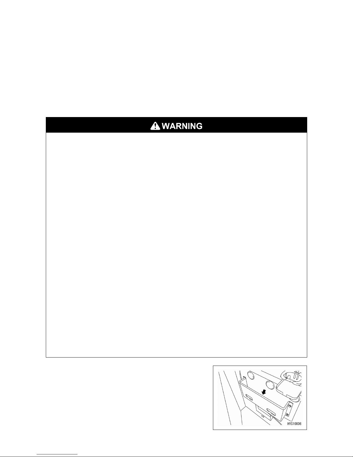
[Storage place of the operation manual]
Magazine box at the left side of operator's seat

3
2. FOR SAFE USE OF THE MACHINE
This manual classifies the risks into the following categories for easy understanding of this
manual and the safety labels attached to this machine.
This denotes that there is an imminent hazard which will cause
serious injury or death.
It also provides information on how to avoid such hazard.
This denotes that there is a hazard which can cause serious injury or
death.
It also provides information on how to avoid such hazard.
This denotes that there is a potential hazard which may cause minor
or moderate injury or serious damage to the machine.
It also provides information on how to avoid such hazard.
This manual also uses the following indications to provide other precautions for handling the
machine and helpful information.
This denotes that failure to properly handle the machine may damage
it or shorten its life.
This denotes helpful information.
The operations, inspections, maintenance and safety precautions for this machine that are
outlined in this manual are relevant to specified tasks.
Thus, the precautions given in this manual and on this machine do not necessarily cover
every safety issue.
When performing the machine operation, inspection or maintenance in a situation that is not
covered by this manual, be sure to take necessary measures and actions for safety on your
own.
Even in the above case, never attempt work or operations that this manual prohibits you to
do.
CAUTION
NOTES

4
3. MACHINE OVERVIEW
3.1 SPECIFIED OPERATIONS
This machine is to be used for the following operations:
• Crane operation
• Travelling suspension operation
This machine is a mobile crane consisting of the upper swiveling body equipped with a boom
type crane and the lower crawler type carrier.
This self-propelled crane is capable of moving (travelling) in the worksite and lifting an object
weighing up to the rated total load.
3.2 MACHINE STRUCTURE
(1) Carrier
(2) Upper slewing body
(3) Safety device
In this manual, the front, rear, left and right directions are
defined with the basic reference direction that the operator sits
on the operator's seat with the carrier's sprocket (A) at the rear
and viewing the machine's traveling direction (forward). For the
slewing of boom (upper slewing body), the boom slewing
directions (clockwise for right and counterclockwise for left)
are determined as viewed from above the machine.
EXTERNAL VIEW

5
This machine is composed of the following units and systems:
[1] CARRIER
Consists of the traveling system.
[2] CRANE
Consists of the engine, travelling operation unit, crane operation unit, boom telescoping unit,
boom derricking unit, slewing unit, hook block and winch system.
[3] SAFTEY DEVICE
Comprises the overwinding prevention device, over-unwinding prevention device, overload
preventive device, slinging rope detachment protector, hydraulic safety valve, telescoping
cylinder hydraulic automatic locking device, derricking cylinder hydraulic automatic locking
device, alarm buzzer, machine body inclination alarm, leveling instrument, working status lamp,
and the crane and travelling operation locking lever.
3.3 MACHINE FUNCTIONS
[1] CARRIER
• The carrier is of a crawler type, which facilitates running in rough terrain and soft ground.
• Operating the two travelling levers enables not only travelling direction changes (forward,
backward, right and left) but also pivot turns and spin turns.
[2] UPPER SLEWING BODY
• The upper slewing body is allowed to perform 360 degrees slewing by slewing operation.
• Through the combined use of the telescopic boom, derrick and slewing systems besides the
winch system, the crane can raise and lower the hook block to move the lifted object to the
desired position within the rated total load and the specified working envelope.

6
4. QUALIFICATION FOR OPERATION
•A high incidence of occupational accidents in crane operation has been reported.
Be aware that experienced engineers are also no exception.
•
Warnings and precautions defined in this manual shall be observed for safety
assurance during operation of the machine.
4.1 QUALIFICATION FOR CRANE OPERATION
Only personnel that have obtained the required license or training stipulated by laws and
regulations applicable to the place of use are qualified to operate this machine.
Contact the relevant government office or our sales service agency for further information.

7
5. CRANE TERMINOLOGY
5.1 TERMS AND DEFINITIONS
[1] RATED TOTAL LOAD
The maximum load that can be applied according to the
boom length and angle. The load includes the mass
(weight) of hoisting accessories (hooks) and slinging
ropes.
[2] RATED LOAD
A load derived by subtracting the mass (weight) of hoisting
accessories (hooks) and slinging ropes from the rated total
load, and can be hoisted.
[3] WORKING RADIUS
A horizontal distance between the axis of slewing and the
hook centre.
[4] BOOM LENGTH
Refers to the distance between the boom primary pin and
the sheave pin of the boom end.
[5] BOOM DERRICK ANGLE
Refers to the angle which the boom forms with the horizon.
[6] LIFTING HEIGHT ABOVE GROUND
A vertical distance between the hook bottom end and the
ground with the hook raised to the upper limit.

8
5.2 DIAGRAM OF WORKING RADIUS AND LIFTING HEIGHT
• The working radius/lifting height shows relationship between working radius, boom
angle and lifting height above ground of this machine with no load hoisted, and
deflection of the boom is not included.
• Stage "4" in the diagram of working radius and lifting height indicates that one half
portion of the " mark" is extruding from the 4th stage boom.
1. The point A in the figure at right indicates the boom angle
and point B the lifting height above ground.
The working radius of points A and B are the same.
2. The "diagram of working radius and lifting height" shows
the relationships between the working radius, boom
angle and lifting height at no load, allowing for no
deflection in the boom.
A deflection occurs in the boom when an object is hoisted,
which causes the working radius to widen slightly.
The rated total load decreases with increase in the
working radius. Actual crane operation requires the
planning of work, allowing for sufficient clearance more
than that provided in the diagram.

9
5.3 RATED TOTAL LOAD CHART
• Rated total load chart is based on level, hard ground.
• Values given in the rated total load chart are based on the working radius including
the deflection of boom under actual load.
•
When boom (3) is extended even for a minimal extent, perform the work within the
capacity indicated in the column of "boom (3)".
• When boom (4) is
extended even for a minimal extent, perform the work within the
capacity indicated in the column of "boom (4)".
• When more than one-half of the "
mark" of boom (4) is exposed from boom (3),
perform the work within the capacity indicated in the column of "boom (5)".
•
If working radius exceeds the value of Working Radius column in the chart by any
extent, work should be performed within the rated total load in the next column of
Working Radius.
• The value of a rated total load including the mass of hoisting accessories (hook: 90
kg (applicable for 2-fall and 4-fall wire rope) or 20 kg (dedicated for Single-fall hook
wire).

10
The rated total load chart provides the maximum loads that the crane is capable of hoisting
objects depending on boom length by working radius.

11
[1] BOOM LENGTH
In the Rated Total Load Chart, the "4.745 m boom (1)", "7.625 m boom (2)", "10.505 m boom
(3)", "13.385 m boom (4)" and "16.265 m boom (5)" given in columns on the top denote the
respective states of the following figures:
1. "4.745m boom (1)":All the booms are retracted.
2. "7.625 m boom (2)":Booms (3), (4) and (5) are retracted, while boom (2) alone is fully
extended.
If boom (2) is extended even to a small extent, perform the work in the capacity indicated in
this column.
3. "10.505 m boom (3)": (4) and (5) are retracted, while booms (2) and (3) are fully extended.
If boom (3) is extended even to a small extent, perform the work in the capacity indicated in
this column.

12
4. "13.385 m boom (4)": Booms (2) and (3) are fully extended, while booms (4) and (5) are
extended to an intermediate length ( mark) is exposed half way from boom (3).
If booms (4) and (5) are extended even to a small extent, perform the work in the capacity
indicated in this column.
5. "16.265 m boom (5)": All the booms are fully extended.
When more than one-half of the " mark" of boom (4) is exposed from boom (3), perform
the work within the capacity indicated in this column.
Other manuals for CC1485S-1
1
Table of contents
Other Maeda Construction Equipment manuals

Maeda
Maeda MC-285C User manual

Maeda
Maeda MC815C User guide

Maeda
Maeda CC1485S-1 User guide

Maeda
Maeda MC285C-3 User manual

Maeda
Maeda MC-174CRM User manual

Maeda
Maeda LC383M-5 User manual

Maeda
Maeda CC1908S-1 User guide

Maeda
Maeda MC174 User manual

Maeda
Maeda MC405C-3 User manual

Maeda
Maeda CC1908S-1 User manual

Maeda
Maeda MK1033C-1 User manual

Maeda
Maeda LC1385M-8B User manual

Maeda
Maeda MC-174CRM User manual

Maeda
Maeda HIRD MC815 User manual

Maeda
Maeda CC1908S-1 User manual

Maeda
Maeda MC-104C-2 User manual

Maeda
Maeda MC-305C-2 User manual

Maeda
Maeda LC1385M-8BF User manual

Maeda
Maeda MC285CB-3 User manual

Maeda
Maeda MC285C-2 User manual