manuals.online logo
Brands
  1. Home
  2. •
  3. Brands
  4. •
  5. Magnescale
  6. •
  7. Measuring Instrument
  8. •
  9. Magnescale LH72 Manual

Magnescale LH72 Manual

1/12
LH72 initial Setup Manual
LH72
Ver.4 (2020.11) CS&S
Confirmation: software version 4.04
LH72
Initial Setup Manual
Contents Page
Preparations before making the initial settings (checking conditions of use) 2 to 3
How to set up Basic Settings 4 to 6
How to set up Detailed Settings (continued from Basic Settings) 7
Factory Default (All Clear) 9
Appendix 1: Front panel, Alarm indication 10
Appendix 2: Adapter connections (scales and gauges) 11 to 12
Table of contents
STEP 4~5
STEP 1~3
Initial Setup Flow
Basic
Settings
Detailed
Settings
STEP 1~3 STEP 4~5
START Finished
Advance
Preparation
Check the conditions of use
2/12
LH72 initial Setup Manual
Items Indication Description Setting
Addition display Selection of addition axis, addition
conditions, etc.
If you select LATHE (lathe function) in
the type selection, this item will
appear.
2: No addition, count value of the 2nd axis
3: No addition, count value on the 3rd axis
2 Add 3: Count value of 2nd axis + 3rd axis
2 Add -3: Count value of 2nd axis-3rd axis
-2 Add 3: 3rd axis-2nd axis count value
-2Add-3: -2nd axis -3rd axis count value
Destination country Please select the region to be used.
(Displayable units) Std: General Area
US: U.S.A.
JPN: Japan
Measuring unit
resolution
Set the resolution output from the
measurement unit to be used for
each axis.
The resolutions that can be selected
are length and angle.
Expanded selections increase the
number of options.
Length: 0.05 to 100μm
*See Tables 1, 2 and 3
or
Angle: 1 second to 1 degree
*Angular resolution (1sec to 1 degree) when
using a rotary scale
Measuring Unit Output
resolution
connection
cable Adapter *
SR-1711
SR-1711R
0.5μm HK-**C
HK-**CR
SZ05-T01
SR801/ MSS-101
SR801R
0.5μm HK-1**C
HK-2**C
SZ05-T01
SR801/ MSS-101
SR801R
0.5μm CE07-**C SZ51-MS01
+ SZ70-1
SR10 / SR30 /
SR50
SR50-R
0.5μm HK-4**C
HK6-**CR
SZ05-T01
SR118 0.5μm CE05-**C
CH02-**
DZ51
+ SZ70-1
SR108
SR107
0.5μm SZ51-MS01
+ SZ70-1
SR128 0.5μm CH01-**C SZ70-1
SR128 / SR127 0.5μm CH01-LW**C SZ51-MS01
+ SZ70-1
SR138R(GB-ER) 0.5μm CH04-03C
Preparations before making the initial setting (1/2)
By confirming the conditions of use in advance, the setting operation can be performed easily.
Let's start with the basic settings.
Basic Setting Items
default
Table1: Length scale output resolution
* For adapter information, refer to Appendix 2 Adapter Connection in this Manual
Measuring Unit Output
resolution
Adapter/
conversion cable Adapter *
SL110
SL130
10μm PL20B SZ70-1
SL110
SL130
10μm PL20C
SJ300 1μm CH33-**CPD/CED
SJ700 5μm SZ70-1
SJ700A 5μm
Table 2: Digiruler output resolution
Measuring Unit Output
resolution
Adapter/
conversion cable Adapter *
DG-B 0.5μm DZ-51 SZ70-1
DL310B/330B 10μm DZ-51 SZ70-1
DK series 0.1μm or
0.5μm
CE29-**
Table3: Digital gage output resolution
3/12
LH72 initial Setup Manual
Items
Indication
Description Setting
Display resolution
and polarity
Sets the resolution to be displayed for each
axis. A value lower than the input resolution
cannot be set. Selects the value for each
axis, including the polarity (+/-).
The default value is set by the basic setting.
Length: 0.05 to 100μm
or
Angle: 1 second to 1 degree
Scaling Displayed by multiplying the measured value
by the magnification 0.1 times to about 10 times
Error
compensation
Setting of linear compensation and
segmented error compensation Err OFF:off
Lin Err:linear compensation
±600μm/m
*Expanded selections ±1000μm/m
SEG Err:segmented error compensation
Flicker control Flicker prevention function for the smallest
display digit OFF: Function stop
1: Weak
2: Strong
Sleep The display turns off when there is no
movement of the length measurement unit or
key operation for a certain period of time
while the power is on.
It will return when the length measurement
unit is moved or the Key operation is
performed again.
OFF: Do not put to sleep
1: 1 minute later
5: 5 minutes later
10:10 minutes later
30:30 minutes later
60: 60 minutes later
Preparations before making the initial setting (2/2)
Check the usage conditions for Detailed Settings.
(Since the setting conditions can be changed later, use the default values to skip items for which
the conditions have not been confirmed)
Detailed Setting Items
default
4/12
LH72 initial Setup Manual
LH72 (3 axes input)
After about 2 seconds
ADD(Z-axis addition axis setting):
Selection of length measurement unit
input for input 2nd axis and input 3rd axis,
and setting of addition display (Note)
Note: When displaying the Z axis in
addition, be sure to connect a scale
with high resolution to input 2 of the
display unit.
Edit key
DC input
How to set up Basic Settings (1/3)
When the power is turned on for the first
time after shipment from the factory
Connect the AC adapter and turn the primary power "on".
Step 1
When you want to change the basic
settings
The following display appears
Note:
If you change the basic settings,
Detailed Settings will be reset to the factory defaults.
Configure the basic settings.
Choose one of the following methods of operation.
Connecting the AC Adapter
AC primary power source
Standby key light
Item feed Key
SET-UP key
Enter key
Axis selection Key
Continued on next page
COUNTRY (destination country):
Please select your region
Signal resolution
(Measuring unit resolution):
Sets the output resolution of the
scale to be connected. Supports the
input of length and angle display
units.
Symbol Destination Unit
STD General area
US U.S.A.
JPN Japan
COUNTRY (Destination)
COUNTRY
(destination)
ADD
(addition display)SIG RES
(measuring unit resolution)
AC adapter is energized.
Turn on key, the LED light changes from
“blinking” to “off” and then press
and hold key for 3 seconds.
Pressing key changes the basic setting mode in the order in which it is set.
5/12
LH72 initial Setup Manual
input 3- input 2
input 2
input 3
input 2 + input 3
input 2 – input 3
- (input 2 + input 3)
How to set up Basic Settings (2/3)
Enter the settings confirmed in "Preparations before making initial settings (1/2)".
Repeat steps (1), (2), and (3) to make the basic settings.
Step 2
COUNTRY
(destination)
ADD
(addition display)SIG RES
(measuring unit resolution)
STANDARD
(General area)
U.S.A.
JAPAN
0.5μm
0.1μm
10μm
5μm
1μm
10 minutes
1 minute
10 seconds
1 second
How to view extended
settings:
For extended settings,
press key(EDIT)
when the input resolution
of each axis is displayed.
2μm
100μm
50μm
25μm
20μm
0.05μm
1 degree
default
default
Basic Settings
(1) Use key to change the basic setting item.
(2) The setting selection can be switched with key on the right side of the counter display.
(3) To define the new value, press key.
Display method:
- For each setting item, the current setting
contents are displayed after about 1 second. If
there is no change in the contents, move to the
next section with key.
6/12
LH72 initial Setup Manual
Setup key
Enter key
Select axis key
Reset key
ABS lamp
Φ lamp
(two times display)
Axis label lamp
Key to be used at the end of the basic setting mode (LH72)
Step 3 Once you have completed the basic settings, exit this mode and move to
Detailed Setting mode.
How to set up Basic Settings (3/3)
How to Exit Basic Setting Mode
①Press key or key.
②The display changes to .
③Pressing key displays .
④Press key.
⑤Press key. The display returns to normal.
This completes the basic settings.
Edit key
7/12
LH72 initial Setup Manual
・Display resolution is set by pressing key on each axis.
・A value smaller than the input resolution cannot be selected.
・Polarity changes with key
・To display the diameter (double display), turn on on the
display axis.
Scaling magnification input
≤≤
magnification
Diameter display
Display resolution
SCALING
(scaling)
Angle display
Length display
Extended resolution
Press the edit key
How to set up Detailed Settings (1/1) (continued from Basic Settings)
Step 4 Make the detailed settings. *If you have already completed the basic settings and want to
reconfigure only the advanced settings, you can do the same.
Basic Settings
Press the setup key
in the normal count display state.
Detailed Settings
default
No compensation
Error compensation off
Linear compensation
Linear Error
Segmented error compensation
Segmentation Error
Error Setting
(compensation value) Selection of error compensation function
default
~
Input a correction value of ±0.600 mm for a distance
of 1 m. Input up to ±1.000 mm when extended is
selected.
~
Extended res.
Normal
Enter with the number keys
Segmentation Error
(Segmented error compensation)
For the operation method, refer to the instruction
manual or the simple manual (Segmented error
compensation).
Segmented error compensation function uses a scale
with reference point to correct mechanical errors for
each interval.
The range that can be corrected is the range of the
counter display based on the reference point position.
In order to use this function, it is necessary to
measure the section error of the machine with a laser
interferometer, length reference device, etc. in
advance.
Liner Error
(Linear compensation)
default
8/12
LH72 initial Setup Manual
FLICKER
(flicker control)
SLEEP
(sleep)
Step 5
Inhibition Weak Inhibition Strongoff
Flickering of the smallest digits can be suppressed in two stages
default
1 min.
none
10 min. 1h
5 min. 30 min.
If no operation or scale movement is performed for a certain
period of time, the display will turn off.
default
6.When the Detailed Settings are complete, switch to the normal display.
Press key.
This completes the initial settings..
Detailed Settings
9/12
LH72 initial Setup Manual
1. Hold down key and key at the same time to start the power supply.
⇒The model name of the counter is displayed
2. When you press key, is displayed,
followed by .
3. Pressing key changes the display as shown below.
4."RUN" LEDs will be lit.
5. Press key to confirm the number of input axis.
6.Turn off the primary power supply of the AC adapter.
In case of LH72-3 is displayed.
To set the factory settings (all clear), perform the following operations.
Make preparation such as taking notes in advance for necessary items.
Also, do not perform any operation other than the explanation.
Factory Default (All Clear)
Mainly used keys
Reference key
Setup key
How to check the software version:
Power ON → Display LH → Key → Version
Press any key to return to the LH display.
Connect the AC adapter to the DC-IN input on the back of the counter and
turn on the primary power supply.
Lights up
”RUN”
Edit key
DC input
Connecting the AC Adapter
AC primary power source
START
completion
→ → →
→ → →
Caution: If you do this, all settings will be the factory default settings.
10/12
LH72 initial Setup Manual
No. Name No. Name No. Name
①Axis label ⑧ABS/INC key ⑮TOOL MASTER key
②ABS lamp, Φ lamp ⑨SETUP key ⑯Axis select key
③Counter display ⑩PROG key ⑰Numeric key
④RESET key ⑪Status lamp ⑱Function key
⑤P key ⑫RUN/NEXT key ⑲Tool coordinates (Tool number)
⑥Datum point value setting key ⑬EDIT key
⑦REF key ⑭Standby key
Display Status Display Status
Measurement unit not
connected
Storage data error
Speed over (Note)Error in reference point
detection
Overflow
Program error
Power failure
Program error
Alarm indication
Note: When using an adapter connection (SZ**), no speed override indication is shown, but rather an error message.
Appendix 1
Front panel
(Blinking)
11/12
LH72 initial Setup Manual
Appendix 2-1 Adapter connection (Length scale)
SZ51-MS01/SZ51-DR01
* HA13A, 15A, 23A and 25A are used as head amps
Screws
Screws
Screws
Head-amp
Connector
SZ05-T01
Connector
Screws
Cable (300mm)
SZ70-1
Counter unit
Head-amp
connector
Screws
Cable (300mm)
Counter unit
Screws
Use screws to secure it in place.
SZ70-1
Use screws to secure it in place.
Scale/ Head Resolution Adapter Counter
SR128(GB-A) 0.5μm SZ70-1 LG20
LH70/71/71A/72
LY71/72
PL20B 10μm
SJ700 5μm
Scale/ Head Resolution Adapter 1 Adapter 2 Counter
SR108(GB) 0.5μm SZ51-MS01 SZ70-1 LG20
LH70/71/71A/72
LY71/72
PL20A 10μm SZ51-DR01
Scale Resolution Adapter Counter
SR-1711(GP)、SR10A/741(GS)、
SR50A(GF,GF-R)、SR30A(GM)、
SR801/801R(GL)
0.5μm SZ05-T01 LG20
LH70/71/71A/72
LY71/72
12/12
LH72 initial Setup Manual
DZ51
Adapter connection (Digital gauge)
Gauge Resolution Adapter 1 Adapter 2 Counter
DG-B 0.5μm DZ51 SZ70-1 LG20
LH70/71/71A/72
LY71/72
DL310B/330B 10μm
Gauge Resolution Adapter Counter
DG 0.5μm SZ05-T01 LG20
LH70/71/71A/72
LY71/72
Screws
Screws
Screw
Appendix 2-2
Head-amp
Connector
Connector
Screws
SZ05-T01
connector
Cable (300mm)
SZ70-1
Counter unit
Head-amp
Screws
Cable (300mm) Counter unit
Use screws to secure it in place.
SZ70-1
Gauge Resolution Adapter Counter
DE12BR/30BR 0.1μm SZ70-1 LG20
LH70/71/71A/72
LY71/72
Gauge Resolution Connection cable Counter
DK-** 0.1μm
or
0.5μm
CE29-**
**: 003/01/03/05/10
(0.3 to 10m)
LG20
LH70/71/71A/72
LY71/72 Counter unit
Screws
DK series CE29-**
Use screws to secure it in place.

Other manuals for LH72

1

Other Magnescale Measuring Instrument manuals

Magnescale SR85 Owner's manual

Magnescale

Magnescale SR85 Owner's manual

Magnescale SR87 Owner's manual

Magnescale

Magnescale SR87 Owner's manual

Magnescale SR77 Owner's manual

Magnescale

Magnescale SR77 Owner's manual

Magnescale DF800S Series User manual

Magnescale

Magnescale DF800S Series User manual

Magnescale DS10NR5 User manual

Magnescale

Magnescale DS10NR5 User manual

Magnescale DT12N User manual

Magnescale

Magnescale DT12N User manual

Magnescale LY71 User manual

Magnescale

Magnescale LY71 User manual

Magnescale PL101 Series User manual

Magnescale

Magnescale PL101 Series User manual

Magnescale LH71 Series User manual

Magnescale

Magnescale LH71 Series User manual

Magnescale DK812 Series User manual

Magnescale

Magnescale DK812 Series User manual

Magnescale MJ632 User manual

Magnescale

Magnescale MJ632 User manual

Magnescale LY71 Manual

Magnescale

Magnescale LY71 Manual

Magnescale U12B User manual

Magnescale

Magnescale U12B User manual

Magnescale DK812A Series User manual

Magnescale

Magnescale DK812A Series User manual

Magnescale DG205 Series User manual

Magnescale

Magnescale DG205 Series User manual

Magnescale DK802 Series User manual

Magnescale

Magnescale DK802 Series User manual

Magnescale LY72 Manual

Magnescale

Magnescale LY72 Manual

Magnescale LY71 Service manual

Magnescale

Magnescale LY71 Service manual

Magnescale SR75 Owner's manual

Magnescale

Magnescale SR75 Owner's manual

Magnescale DS50NR5 User manual

Magnescale

Magnescale DS50NR5 User manual

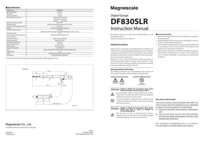
Magnescale DF830SLR User manual

Magnescale

Magnescale DF830SLR User manual

Magnescale DZ176 User manual

Magnescale

Magnescale DZ176 User manual

Magnescale DK812S Series User manual

Magnescale

Magnescale DK812S Series User manual

Magnescale DL310B User manual

Magnescale

Magnescale DL310B User manual

Popular Measuring Instrument manuals by other brands

Task Force Tips MONSOON MONITOR Instructions for installation, safe operation and maintenance

Task Force Tips

Task Force Tips MONSOON MONITOR Instructions for installation, safe operation and maintenance

SATO SK-L750 instruction manual

SATO

SATO SK-L750 instruction manual

BLUE JAY BJ192I user manual

BLUE JAY

BLUE JAY BJ192I user manual

Tractel dynafor Expert 0.5 Installation, operating and maintenance manual

Tractel

Tractel dynafor Expert 0.5 Installation, operating and maintenance manual

OHAUS ST400D-B instruction manual

OHAUS

OHAUS ST400D-B instruction manual

Siemens SITRANS DA400 operating instructions

Siemens

Siemens SITRANS DA400 operating instructions

FRC ThrottleXcel ELA100 manual

FRC

FRC ThrottleXcel ELA100 manual

Veesta World V-PM2000 Series user manual

Veesta World

Veesta World V-PM2000 Series user manual

Micronics PF D550 user guide

Micronics

Micronics PF D550 user guide

Endress+Hauser Prosonic FDU80 Safety instructions

Endress+Hauser

Endress+Hauser Prosonic FDU80 Safety instructions

Marathon Austin BA030018 manual

Marathon

Marathon Austin BA030018 manual

EMX Industries Brite-X 100 operating instructions

EMX Industries

EMX Industries Brite-X 100 operating instructions

Endress+Hauser Gammapilot M FMG50 Brief operating instructions

Endress+Hauser

Endress+Hauser Gammapilot M FMG50 Brief operating instructions

Panduit CDE3 installation instructions

Panduit

Panduit CDE3 installation instructions

Fluke 700G Series Manual supplement

Fluke

Fluke 700G Series Manual supplement

Endress+Hauser Proline Promass 80 operating instructions

Endress+Hauser

Endress+Hauser Proline Promass 80 operating instructions

Bosch GAM Professional 220 Original instructions

Bosch

Bosch GAM Professional 220 Original instructions

Phoenix Controls FSR100 manual

Phoenix Controls

Phoenix Controls FSR100 manual

manuals.online logo
manuals.online logoBrands
  • About & Mission
  • Contact us
  • Privacy Policy
  • Terms and Conditions

Copyright 2025 Manuals.Online. All Rights Reserved.