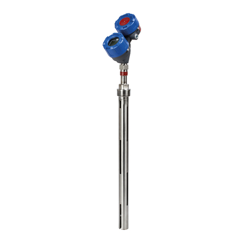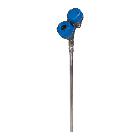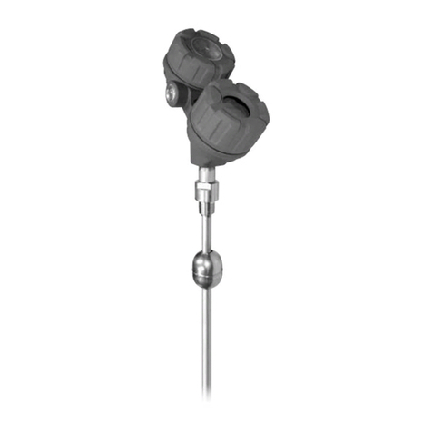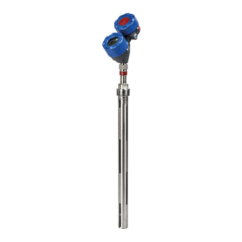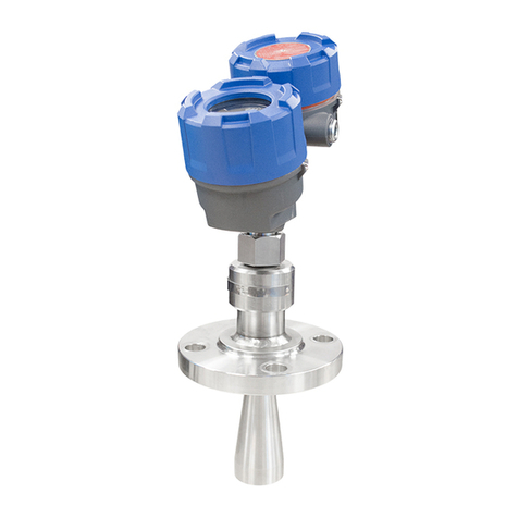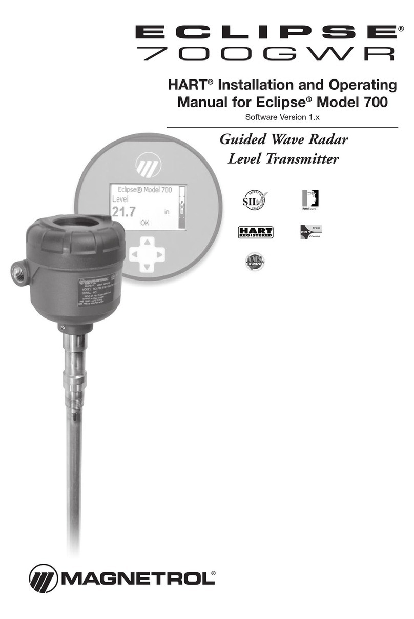
57-642 ECLIPSE Model 705 Guided Wave Radar Transmitter for Hygienic Industries
Table o Contents
1.0 QuickStart Installation
1.1 Getting Started..........................................................4
1.1.1 Equipment and Tools..................................... 4
1.1.2 Configuration Information.............................5
1.2 Qui kStart Mounting................................................5
1.2.1 Probe..............................................................5
1.2.2 Transmitter.....................................................6
1.3 Qui kStart Wiring.................................................... 6
1.4 Qui kStart Configuration......................................... 7
2.0 Complete Installation
2.1 Unpa king................................................................ 8
2.2 Ele trostati Dis harge (ESD) Handling Pro edure...8
2.3 Before You Begin.......................................................9
2.3.1 Site Preparation.............................................. 9
2.3.2 Equipment and Tools..................................... 9
2.3.3 Operational Considerations............................9
2.4 Mounting..................................................................9
2.4.1 Prior to Installing a Hygieni
Single Rod Probe..........................................10
2.4.1.1 To install a Model 7xF or Model 7xH
Single Hygieni Probe...........................10
2.4.2 Installing the Transmitter............................. 11
2.4.2.1 Integral Mount......................................11
2.4.2.2 Remote Mount......................................11
2.5 Wiring.................................................................... 12
2.5.1 General Purpose or Non-In endive
(CI I, Div 2)................................................. 12
2.5.2 Intrinsi ally Safe........................................... 13
2.5.3 Explosion Proof............................................13
2.6 Configuring the Transmitter....................................14
2.6.1 Operating Parameters................................... 14
2.6.2 Setting Up for Ben h Configuration............ 14
2.6.3 Transmitter Display and Keypad.................. 15
2.6.4 Password Prote tion (Default = 0)................15
2.6.5 Model 705 Menu: Step-By-Step Pro edure.. 16
2.6.5.1 Measurement Type: Level Only.............16
2.6.5.2 Measurement Type: Level and Volume..19
2.6.6 Offset Des ription........................................22
2.7 Configuration Using HART®..................................23
2.7.1 Conne tions................................................. 23
2.7.2 Display Menu...............................................23
2.7.3 HART Menu – Model 705 3.x.................... 24
2.7.4 HART Revision Table.................................. 25
3.0 Reference Information
3.1 Des ription............................................................. 25
3.2 Theory of Operation...............................................26
3.2.1 Mi ropower Impulse Radar.......................... 26
3.2.2 Time Domain Refle tometry (TDR)............26
3.2.3 Equivalent Time Sampling (ETS).................26
4.0 Initial Start-Up
4.1 Probe Lo ation.........................................................27
4.2 Probe Bends............................................................. 27
4.2.1 Shallow Bends................................................28
4.2.2 Field Bends.................................................... 28
4.2.3 A ommodating Non-Linearity..................... 29
4.3 Ele troni s Mounting...............................................30
4.4 Basi Start-Up.......................................................... 30
4.4.1 Probe Length................................................. 30
4.4.2 Blo king Distan e and Damping .................. 30
4.4.3 Strapping Tables.............................................31
4.4.4 Tuning/Optimization..................................... 32
4.4.4.1 Diele tri Range/Sensitivity.....................32
4.4.4.2 PACTware E hoCurve............................. 32
4.4.4.3 Blo king Distan e................................... 32
4.4.4.4 E ho Curves in Dry and Filled States......32
4.4.4.5 Strapping Table Configuration................ 33
4.4.4.6 Additional Considerations.......................33
5.0 Troubles ooting
5.1 Troubleshooting System Problems............................34
5.2 Status Messages........................................................ 35
5.3 Agen y Approvals.....................................................37
5.3.1 Agen y Spe ifi ations (XP Installation)..........37
5.3.2 Agen y Spe ifi ations (IS Installation)........... 38
5.3.3 Agen y Spe ifi ations (FOUNDATION fieldbus)... 39
6.0 Parts
6.1 Repla ement Parts....................................................40
6.2 Re ommended Spare Parts....................................... 40
7.0 Specifications
7.1 Fun tional................................................................41
7.1.1 O-Ring (Seal) Sele tion Chart....................... 41
7.2 Performan e (Model 705)........................................ 42
7.3 Pro ess Conditions...................................................43
7.4 Probe Spe ifi ations................................................. 43
7.5 Physi al.................................................................... 44
8.0 Model Numbers
8.1 Transmitter...............................................................45
8.2 Probe........................................................................46
9.0 Dry Calibration Procedure
9.1 Calibration Verifi ation............................................47
9.1.1 Wet Calibration Verifi ation of ECLIPSE......47
9.1.2 Dry Calibration Verifi ation of ECLIPSE......47
9.1.3 Dry Calibration Verifi ation Ben h................47
9.2 Pro edure to Verify Calibration of ECLIPSE........... 48
9.2.1 Initial Baseline Verifi ation of ECLIPSE........48
9.2.2 Subsequent Calibration Verifi ation...............48
9.3 Sample Calibration Verifi ation Do ument..............49
10.0 Hygienic Probe Rebuild Procedure..............................50
10.1 Model 7xH............................................................ 50
10.2 Model 7xF-E..........................................................51
Model 705 Configuration Data S eet................................. 52
Strapping Table Data S eet.................................................54
Appendix A: GWR – Emitted Energy................................. 55
Appendix B: Indexing Bent GWR Probes in Vessels............56
Appendix C: Segmented Probes...........................................58
