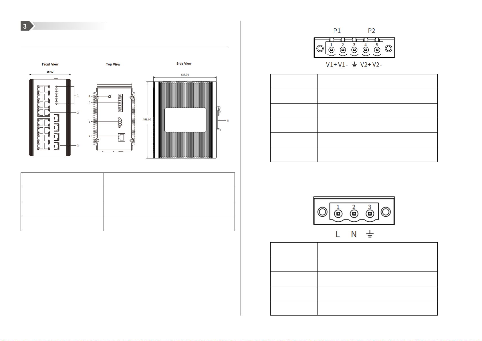
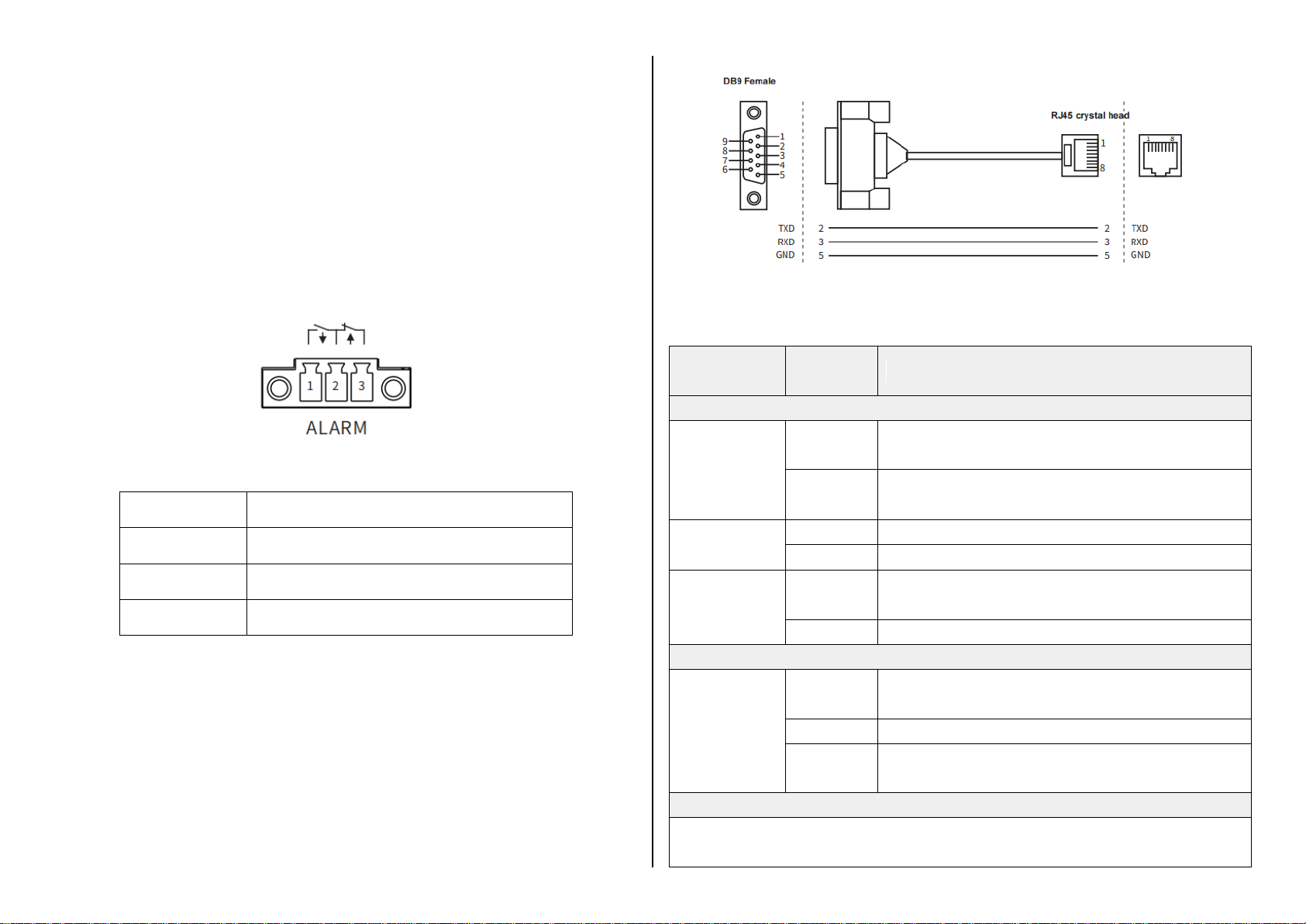
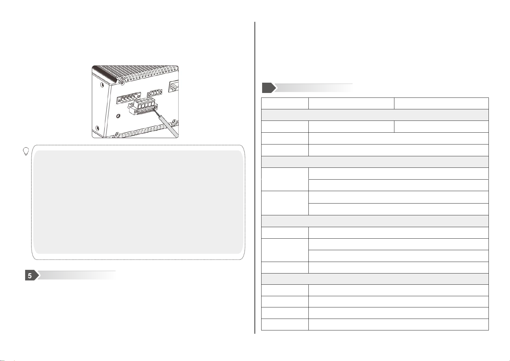
Maiwe MISCOM7220G-4GF-16GT User manual
Other Maiwe Switch manuals

Maiwe
Maiwe MIEN5208 Series User manual

Maiwe
Maiwe MISCOM8028GX-4XGF-16GF-8GC User manual

Maiwe
Maiwe Admas2208P-M12-8TPOE User manual

Maiwe
Maiwe MIEN2016 User manual

Maiwe
Maiwe MIGE2206G-2GF-4GT User manual

Maiwe
Maiwe MISCOM7212GP Series User manual

Maiwe
Maiwe MISCOM8028-4GF User manual

Maiwe
Maiwe MIEN2208-F User manual

Maiwe
Maiwe MIEN2205 User manual

Maiwe
Maiwe MIEN2216 User manual

Maiwe
Maiwe MIEN2208 Series User manual

Maiwe
Maiwe MIEN1203 User manual

Maiwe
Maiwe MIEN2204 Series User manual

Maiwe
Maiwe MISCOM7028GX Series User manual

Maiwe
Maiwe MISCOM8220G User manual

Maiwe
Maiwe MIEN2206 User manual

Maiwe
Maiwe MIEN6208 Series User manual

Maiwe
Maiwe MIEN2208 Series User manual

Maiwe
Maiwe MIEN3020G-4GC-16GT User manual

Maiwe
Maiwe MIGE2210 Series User manual


Popular Switch manuals by other brands

SMC Networks
SMC Networks SMC6224M Technical specifications

Aeotec
Aeotec ZWA003-S operating manual

TRENDnet
TRENDnet TK-209i Quick installation guide

Planet
Planet FGSW-2022VHP user manual

Avocent
Avocent AutoView 2000 AV2000BC AV2000BC Installer/user guide

Moxa Technologies
Moxa Technologies PT-7728 Series user manual

Intos Electronic
Intos Electronic inLine 35392I operating instructions

Cisco
Cisco Catalyst 3560-X-24T Technical specifications

Asante
Asante IntraCore IC3648 Specifications

Siemens
Siemens SIRIUS 3SE7310-1AE Series Original operating instructions

Edge-Core
Edge-Core DCS520 quick start guide

RGBLE
RGBLE S00203 user manual