REPAIR
For repairing methods, proceed in the same orders as 2414B except for swinging function at support point of 2414B.
1.Disassembling of the handle and switch
Unless the motor housing has been removed, the handle R cannot be disconnected. To disconnect the
handle R, first remove the motor housing. (See 2. Disassembling of the motor.)
2.Disassembling of the motor
After removing the carbon brush(2 pieces), remove the pan head screws M5(4 pieces) for mounting themotor housing
and pan head screws M5(3 pieces) for mounting the handle to separate the one body of motor housing and handle from
the gear housing, and then you can take away the armature.
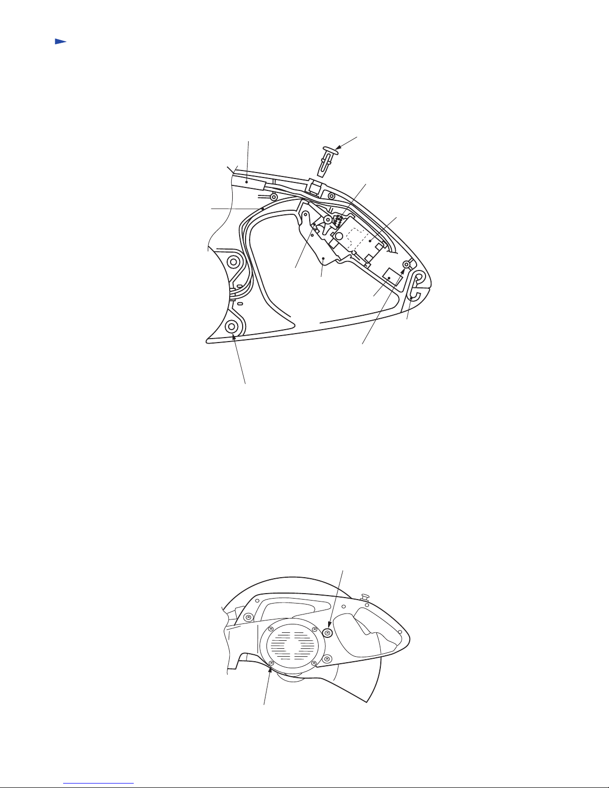
Cab tire cord Switch button
Compression spring
Switch
Hanger
Condenser
Switch lever
Switch lock
Lead wire
from the field
Tapping screws(3 pieces)
for mounting handle R/L
Pan head screws M5(3 pieces)
for mounting handle
Pan head screws M5(3 pieces)
for mounting the handle
Pan head screws M5(4 pieces)
for mounting the motor housing
The handle R/L are fixed with 4 pieces of tappingscrews and are mounted on the gear housing withthe 3 pan head
screws M5. To disconnect the handleL, disconnect these 7 screws. See the figure for the switch structure.