Makita DSC163 User manual

GB Cordless Steel Rod Cutter
Instruction manual
DSC163

2
12
34
56
78
1
2
3
4
5
6
7
89
10
11
12
13
11
11
12
13
11
12

3
910
11 12
13 14
15 16
12
14
11
12
13
15
16
17
11
18 19
20
21
22
23
24
22
25
26
27

4
ENGLISH (Original instructions)
Explanation of general view
SPECIFICATIONS
• Due to our continuing program of research and development, the specifications herein are subject to change without
notice.
• Specifications and battery cartridge may differ from country to country.
• Weight, with battery cartridge, according to EPTA-Procedure 01/2014
Applicable battery cartridge
BL1830 / BL1830B / BL1840 / BL1840B / BL1850 / BL1850B / BL1860B
• Some of the battery cartridges listed above may not be available depending on your region of residence.
WARNING:
•Only use the battery cartridges listed above. Use of any other battery cartridges may cause injury and/or fire.
Symbols
The following show the symbols used for the equipment.
Be sure that you understand their meaning before use.
Intended use
The tool is intended for cutting rebar.
Noise
The typical A-weighted noise level determined according
to EN60745-1:
Sound pressure level (LpA) : 78 dB(A)
Uncertainty (K) : 3 dB(A)
The noise level under working may exceed 80 dB (A).
Wear ear protection
Vibration
The vibration total value (tri-axial vector sum) determined
according to EN60745-1:
Work mode : cutting rebar
Vibration emission (ah) : 2.5 m/s2or less
Uncertainty (K) : 1.5 m/s2
• The declared vibration emission value has been
measured in accordance with the standard test method
and may be used for comparing one tool with another.
• The declared vibration emission value may also be
used in a preliminary assessment of exposure.
1. Red indicator
2. Button
3. Battery cartridge
4. Star marking
5. LED indicator
6. Switch Lock
7. Switch trigger
8. Side A
9. Side B
10. Protector
11. Rebar
12. Blades
13. Stopper
14. More than 200 mm
15. Air Hole
16. Hex Wrench
17. Return Valve
18. Blade A (Thicker Blade)
19. Blade B (Thinner Blade)
20. Bolt (Longer)
21. Bolt (Shorter)
22. Washer
23. Bar Holder
24. Cutter Rod
25. Blade A on Bar Holder
26. Blade B on Cutter Rod
27. Spare Blades
Model DSC163
Max. Cutting Capacity (Dia.mm)
16 mm
Grade 40 - Grade 60
Grade 40: Tensile Strength 490 N/mm270,000 PSI
Grade 60: Tensile Strength 620 N/mm290,000 PSI
Cutting Speed 2.8 seconds
Overall length 360 mm
Net weight 6.9 kg
Rated voltage D.C. 18V
..... Read instruction manual.
........ Only for EU countries
Do not dispose of electric equipment or
battery pack together with household
waste material!
In observance of the European
Directives, on Waste Electric and
Electronic Equipment and Batteries and
Accumulators and Waste Batteries and
Accumulators and their implementation in
accordance with national laws, electric
equipment and batteries and battery
pack(s) that have reached the end of their
life must be collected separately and
returned to an environmentally
compatible recycling facility.
Cd
Ni-MH
Li-ion

5
WARNING:
• The vibration emission during actual use of the power
tool can differ from the declared emission value
depending on the ways in which the tool is used.
• Be sure to identify safety measures to protect the
operator that are based on an estimation of exposure in
the actual conditions of use (taking account of all parts
of the operating cycle such as the times when the tool
is switched off and when it is running idle in addition to
the trigger time).
EC Declaration of Conformity
For European countries only
The EC declaration of conformity is included as Annex A
to this instruction manual.
General power tool safety
warnings
WARNING: Read all safety warnings, instructions,
illustrations and specifications provided with this
power tool. Failure to follow all instructions listed below
may result in electric shock, fire and/or serious injury.
Save all warnings and
instructions for future reference.
The term “power tool” in the warnings refers to your
mains-operated (corded) power tool or battery-operated
(cordless) power tool.
Work area safety
1. Keep work area clean and well lit. Cluttered or dark
areas invite accidents.
2. Do not operate power tools in explosive
atmospheres, such as in the presence of
flammable liquids, gases or dust. Power tools
create sparks which may ignite the dust or fumes.
3. Keep children and bystanders away while
operating a power tool. Distractions can cause you
to lose control.
Electrical Safety
1. Power tool plugs must match the outlet. Never
modify the plug in any way. Do not use any
adapter plugs with earthed (grounded) power
tools. Unmodified plugs and matching outlets will
reduce risk of electric shock.
2. Avoid body contact with earthed or grounded
surfaces, such as pipes, radiators, ranges and
refrigerators. There is an increased risk of electric
shock if your body is earthed or grounded.
3. Do not expose power tools to rain or wet
conditions. Water entering a power tool will increase
the risk of electric shock.
4. Do not abuse the cord. Never use the cord for
carrying, pulling or unplugging the power tool.
Keep cord away from heat, oil, sharp edges or
moving parts. Damaged or entangled cords increase
the risk of electric shock.
5. When operating a power tool outdoors, use an
extension cord suitable for outdoor use. Use of a
cord suitable for outdoor use reduces the risk of
electric shock.
6. If operating a power tool in a damp location is
unavoidable, use a residual current device (RCD)
protected supply. Use of an RCD reduces the risk of
electric shock.
7. Power tools can produce electromagnetic fields
(EMF) that are not harmful to the user. However,
users of pacemakers and other similar medical
devices should contact the maker of their device and/
or doctor for advice before operating this power tool.
Personal Safety
1. Stay alert, watch what you are doing and use
common sense when operating a power tool. Do
not use a power tool while you are tired or under
the influence of drugs, alcohol or medication. A
moment of inattention while operating power tools
may result in serious personal injury.
2. Use personal protective equipment. Always wear
eye protection. Protective equipment such as a dust
mask, non-skid safety shoes, hard hat or hearing
protection used for appropriate conditions will reduce
personal injuries.
3. Prevent unintentional starting. Ensure the switch
is in the off-position before connecting to power
source and/or battery pack, picking up or carrying
the tool. Carrying power tools with your finger on the
switch or energising power tools that have the switch
on invites accidents.
4. Remove any adjusting key or wrench before
turning the power tool on. A wrench or a key left
attached to a rotating part of the power tool may result
in personal injury.
5. Do not overreach. Keep proper footing and
balance at all times. This enables better control of
the power tool in unexpected situations.
6. Dress properly. Do not wear loose clothing or
jewellery. Keep your hair and clothing away from
moving parts. Loose clothes, jewellery or long hair
can be caught in moving parts.
7. If devices are provided for the connection of dust
extraction and collection facilities, ensure these
are connected and properly used. Use of dust
collection can reduce dust-related hazards.
8. Do not let familiarity gained from frequent use of
tools allow you to become complacent and ignore
tool safety principles. A careless action can cause
severe injury within a fraction of a second.

6
9. Always wear protective goggles to protect your
eyes from injury when using power tools. The
goggles must comply with ANSI Z87.1 in the USA,
EN 166 in Europe, or AS/NZS 1336 in Australia/
New Zealand. In Australia/New Zealand, it is
legally required to wear a face shield to protect
your face, too.
It is an employer's responsibility to enforce the
use of appropriate safety protective equipments
by the tool operators and by other persons in the
immediate working area.
Power tool use and care
1. Do not force the power tool. Use the correct power
tool for your application. The correct power tool will
do the job better and safer at the rate for which it was
designed.
2. Do not use the power tool if the switch does not
turn it on and off. Any power tool that cannot be
controlled with the switch is dangerous and must be
repaired.
3. Disconnect the plug from the power source and/or
remove the battery pack, if detachable, from the
power tool before making any adjustments,
changing accessories, or storing power tools.
Such preventive safety measures reduce the risk of
starting the power tool accidentally.
4. Store idle power tools out of the reach of children
and do not allow persons unfamiliar with the
power tool or these instructions to operate the
power tool. Power tools are dangerous in the hands
of untrained users.
5. Maintain power tools and accessories. Check for
misalignment or binding of moving parts,
breakage of parts and any other condition that
may affect the power tool’s operation. If damaged,
have the power tool repaired before use. Many
accidents are caused by poorly maintained power
tools.
6. Keep cutting tools sharp and clean. Properly
maintained cutting tools with sharp cutting edges are
less likely to bind and are easier to control.
7. Use the power tool, accessories and tool bits etc.
in accordance with these instructions, taking into
account the working conditions and the work to
be performed. Use of the power tool for operations
different from those intended could result in a
hazardous situation.
8. Keep handles and grasping surfaces dry, clean
and free from oil and grease. Slippery handles and
grasping surfaces do not allow for safe handling and
control of the tool in unexpected situations.
9. When using the tool, do not wear cloth work
gloves which may be entangled. The entanglement
of cloth work gloves in the moving parts may result in
personal injury.
Battery tool use and care
1. Recharge only with the charger specified by the
manufacturer. A charger that is suitable for one type
of battery pack may create a risk of fire when used
with another battery pack.
2. Use power tools only with specifically designated
battery packs. Use of any other battery packs may
create a risk of injury and fire.
3. When battery pack is not in use, keep it away from
other metal objects, like paper clips, coins, keys,
nails, screws or other small metal objects, that can
make a connection from one terminal to another.
Shorting the battery terminals together may cause
burns or a fire.
4. Under abusive conditions, liquid may be ejected
from the battery; avoid contact. If contact
accidentally occurs, flush with water. If liquid
contacts eyes, additionally seek medical help.
Liquid ejected from the battery may cause irritation or
burns.
5. Do not use a battery pack or tool that is damaged
or modified. Damaged or modified batteries may
exhibit unpredictable behaviour resulting in fire,
explosion or risk of injury.
6. Do not expose a battery pack or tool to fire or
excessive temperature. Exposure to fire or
temperature above 130 °C may cause explosion.
7. Follow all charging instructions and do not charge
the battery pack or tool outside the temperature
range specified in the instructions. Charging
improperly or at temperatures outside the specified
range may damage the battery and increase the risk
of fire.
Service
1. Have your power tool serviced by a qualified
repair person using only identical replacement
parts. This will ensure that the safety of the power tool
is maintained.
2. Never service damaged battery packs. Service of
battery packs should only be performed by the
manufacturer or authorized service providers.
3. Follow instruction for lubricating and changing
accessories.

7
CORDLESS STEEL ROD CUTTER
SAFETY WARNINGS
1. Hold the tool securely while it is in use. If the tool is
not held securely, you may be injured.
2. Keep your hands and face away from the moving
parts. They may cause an injury.
3. Release the Switch trigger immediately to stop
operation when the tool is out of order or makes
an abnormal sound during use. Have it inspected
and repaired by an authorized service center.
Failure to do so may result in damage or injury.
4. If you drop or strike the tool, check carefully that
the body is not damaged, cracked, or deformed.
Any such damage could cause injury.
5. This tool is an electro-hydraulic tool. The oil
reservoir was filled before delivery. Do not add oil
unless the tool operates abnormally.
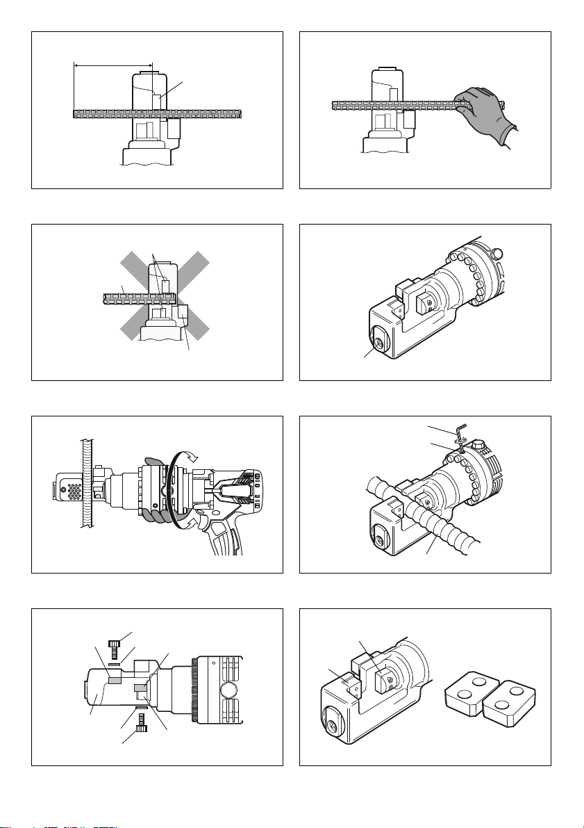
6. Metal cutting blades have sharp edges. Handle
them carefully to avoid being cut.
7. Damaged, deformed or cracked blades may cause
serious accidents as well as impair operation.
Replace with new genuine blades immediately.
SAVE THESE INSTRUCTIONS.
WARNING:
DO NOT let comfort or familiarity with product (gained
from repeated use) replace strict adherence to safety
rules for the subject product. MISUSE or failure to
follow the safety rules stated in this instruction
manual may cause serious personal injury.
Important safety instructions for
battery cartridge
1. Before using battery cartridge, read all
instructions and cautionary markings on (1)
battery charger, (2) battery, and (3) product using
battery.
2. Do not disassemble battery cartridge.
3. If operating time has become excessively shorter,
stop operating immediately. It may result in a risk
of overheating, possible burns and even an
explosion.
4. If electrolyte gets into your eyes, rinse them out
with clear water and seek medical attention right
away. It may result in loss of your eyesight.
5. Do not short the battery cartridge:
(1) Do not touch the terminals with any
conductive material.
(2) Avoid storing battery cartridge in a container
with other metal objects such as nails, coins,
etc.
(3) Do not expose battery cartridge to water or
rain.
A battery short can cause a large current flow,
overheating, possible burns and even a
breakdown.
6. Do not store the tool and battery cartridge in
locations where the temperature may reach or
exceed 50 °C (122 °F).
7. Do not incinerate the battery cartridge even if it is
severely damaged or is completely worn out. The
battery cartridge can explode in a fire.
8. Be careful not to drop or strike battery.
9. Do not use a damaged battery.
10. The contained lithium-ion batteries are subject to
the Dangerous Goods Legislation requirements.
For commercial transports e.g. by third parties,
forwarding agents, special requirement on packaging
and labeling must be observed.
For preparation of the item being shipped, consulting
an expert for hazardous material is required. Please
also observe possibly more detailed national
regulations.
Tape or mask off open contacts and pack up the
battery in such a manner that it cannot move around in
the packaging.
11. Follow your local regulations relating to disposal
of battery.
12. Use the batteries only with the products specified
by Makita. Installing the batteries to non-compliant
products may result in a fire, excessive heat,
explosion, or leak of electrolyte.
SAVE THESE INSTRUCTIONS.
CAUTION: Only use genuine Makita batteries. Use
of non-genuine Makita batteries, or batteries that have
been altered, may result in the battery bursting causing
fires, personal injury and damage. It will also void the
Makita warranty for the Makita tool and charger.
Tips for maintaining maximum battery life
1. Charge the battery cartridge before completely
discharged. Always stop tool operation and
charge the battery cartridge when you notice less
tool power.
2. Never recharge a fully charged battery cartridge.
Overcharging shortens the battery service life.
3. Charge the battery cartridge with room
temperature at 10 °C - 40 °C (50 °F - 104 °F). Let a
hot battery cartridge cool down before charging it.
4. Charge the battery cartridge if you do not use it for
a long period (more than six months).
FUNCTIONAL DESCRIPTION
CAUTION:
• Always be sure that the tool is switched off and the
battery cartridge is removed before adjusting or
checking function on the tool.
Installing or removing battery cartridge
(Fig. 1)
CAUTION:
• Always switch off the tool before installing or removing
of the battery cartridge.
•Hold the tool and the battery cartridge firmly when
installing or removing battery cartridge. Failure to
hold the tool and the battery cartridge firmly may cause
them to slip off your hands and result in damage to the
tool and battery cartridge and a personal injury.

8
To remove the battery cartridge, slide it from the tool while
sliding the button on the front of the cartridge.
To install the battery cartridge, align the tongue on the
battery cartridge with the groove in the housing and slip it
into place. Insert it all the way until it locks in place with a
little click. If you can see the red indicator on the upper
side of the button, it is not locked completely.
CAUTION:
• Always install the battery cartridge fully until the red
indicator cannot be seen. If not, it may accidentally fall
out of the tool, causing injury to you or someone
around you.
• Do not install the battery cartridge forcibly. If the
cartridge does not slide in easily, it is not being inserted
correctly.
Battery protection system (Lithium-ion
battery with star marking) (Fig. 2)
Lithium-ion batteries with a star marking are equipped
with a protection system. This system automatically cuts
off power to the tool to extend battery life.
The tool will automatically stop during operation if the tool
and/or battery are placed under one of the following
conditions:
• Overloaded:
The tool is operated in a manner that causes it to
draw an abnormally high current.
In this situation, release the switch trigger on the tool
and stop the application that caused the tool to
become overloaded. Then pull the switch trigger
again to restart.
If the tool does not start, the battery is overheated. In
this situation, let the battery cool before pulling the
switch trigger again.
• Low battery voltage:
The remaining battery capacity is too low and the tool
will not operate. In this situation, remove and
recharge the battery.
Indicating the remaining battery capacity
(Fig. 3)
(Country specific)
When you pull the switch trigger, the LED display shows
the remaining battery capacity as the following table.
NOTE:
• The LED display goes off approximately one minute
after releasing the switch trigger to save the battery
power. To check the remaining battery capacity, slightly
pull the switch trigger.
• When the LED display lights up but the tool does not
work even with a recharged battery cartridge, cool
down the tool fully. If the condition does not change,
have the tool repaired by a Makita local service center.
OPERATING PROCEDURE
Read, understand and follow all safety instructions and
operating procedures. If you do not understand the
instructions, or if conditions are not correct for proper
operation, do not operate this tool. Consult your
supervisor or other responsible person.
WARNING:
• Before the Battery is inserted into the tool, pull and
release the switch trigger to ensure that it returns when
released.
The motor is on when the switch trigger is pulled and off
when the switch trigger is released.
Switch Lock Operation (Fig. 4)
• Push in the Switch Lock on side A. The Switch is un-
locked and the Trigger can be operated.
• Push in the Switch Lock on side B. The Switch is
locked and the Trigger cannot be operated.
CAUTION:
• The switch trigger should be locked at all times when
not in use.
WARNING:
• Before operation, confirm that the position of the
operator, relative to the tool, and the surrounding area
is safe for operation. Put on safety glasses and wear
protective clothing.
• Refer to the tool specifications in this manual and do
not cut rebar of size or hardness that exceeds the
cutting capacity of the tool.
• Do not cut material other than rebar. Please ask the
manufacturer if you want to cut other materials.
WARNING:
• Replace damaged (chipped, broken, cracked) or
deformed blades immediately. The blade will not cut
true and may fracture or break causing serious
personal injury.
Cutting Procedure
WARNING:
•Never use the tool without the protector in place.
Failure to do so can cause serious personal injury.
(Fig. 5)
• Protector is an equipment to prevent fragments from
being projected towards the operator. It does not
prevent a projection to the axial direction of the rebar.
Position yourself so that the protector blocks the
fragments.
• In some figures the protector is not shown, but it is for
showing the inside of the protector. Always use the
protector in place.
1. Position the rebar to be cut between the blades.
(Fig. 6)
Adjust the Stopper according to the diameter of the
rebar to be cut so that the rebar is at 90 degrees to the
blades. The Stopper supports the rebar and keeps it
perpendicular to the blades when cutting. (Fig. 7)
LED indicator status Remaining battery
capacity
About 50% or more
About 20% - 50%
About less than 20%

9
WARNING:
• When cutting rebar, adjust the Stopper according to the
diameter of the rebar to be cut so that the rebar is at 90
degrees to the blades. Without this adjustment, the cut
piece may fly off and cause serious injury to the
operator or bystanders. Never fail to check the position
of the operator relative to the tool and confirm the
safety of the operator and surrounding area.
2. Position the rebar deep enough between the blades
so that it does not touch the protector. (Fig. 8)
WARNING:
• If the rebar to be cut is not positioned fully between the
blades, the blades will be damaged; the rebar will be
ejected violently and may cause serious personal
injury.
WARNING:
• Do not cut rebar when the piece to be cut off is less
than 200 mm in length. Cutting shorter length may
cause the rebar to fly off during cut and may result in
serious personal injury. (Fig. 9)
WARNING:
• Do not cut rebar when it is not properly supported by
the Stopper. When cutting, hold the rebar on the
Stopper side. (Fig. 10, 11) If not, the cut piece may fly
off and cause serious injury to the operator or
bystanders.
3. Push in the Switch Lock on Side A. The switch is
unlocked and the trigger can be operated.
4. Press the switch trigger to start cutting operation. The
Cutter Rod will move forward to cut the rebar. Keep
the Switch depressed until the Cutter Rod stops at the
end of its stroke.
5. Release the switch trigger when the cut is completed
and the Cutter Rod has reached the end of its stroke.
The Cutter Rod will then return automatically to its
starting position. The Cutter Rod will not return if the
stroke is not completed. Similarly the Cutter Rod will
not be able to move forward again until after it returns
completely to its starting position. Press the switch to
start the next cut, only after the Cutter Rod completely
returns to its starting position and stops.
WARNING:
• When cutting rebar of a high tensile strength the cut
piece may fly off and cause serious injury to the
operator. Wear safety glasses and confirm that the
surrounding area is safe before starting operation.
WARNING:
• Keep your hands and face away from the blades, the
moving parts and the cutting area, during operation.
Remove the Battery from the tool immediately after
use.
NOTE:
• If the temperature of the tool housing exceeds 70°C
(160°F), the tool capacity decreases. In such a case,
stop the use and allow the tool to cool down.
NOTE:
• Keep the air hole in the end of the Bar Holder clear of
dirt and debris. The air hole controls the internal
pressure and should not be obstructed. (Fig. 12)
Rotating Function of Motor (Fig. 13)
The Motor Body can be rotated through 360 degrees, in
either direction, during operation. This feature is
particularly useful when working in awkward or narrow
areas as it allows the operator to position the tool in the
best position for easy operation.
Return Valve Operation (Fig. 14)
The function of the Return Valve is to allow the Cutter Rod
to return to the starting position if it is unable complete a
cut or becomes jammed. Loosening the return valve half
turn will release the oil pressure and allow the Cutter Rod
to return. Retighten the Return Valve once the Cutter Rod
is fully returned and before starting the next operation.
BLADES REPLACEMENT
PROCEDURE
If the cutting edges of the blades are chipped, cracked,
deformed, or damaged in any way, their cutting ability will
be reduced. Cutting under such conditions may cause
further damage and result in personal injury. The blades
should be replaced as a set immediately if any damage is
found.
WARNING:
• When replacing the blades, ensure that the Battery is
removed from the tool to prevent accidental operation.
Ensure that Blade A, on the Bar Holder and Blade B, on
the Cutter Rod are fitted in their correct respective
positions. (Fig. 15)
1. Undo the bolts and the washers that hold Blade A and
Blade B.
2. Remove dirt and clean the surfaces where the new
blades are to be fitted.
3. Fit Blade A to the Bar Holder and Blade B to the Cutter
Rod. Replace bolts and washers and tighten firmly.
WARNING:
• The bolts that hold Blade A and Blade B should be
tightened regularly. If the bolts become loose the
Blades may be damaged and may cause personal
injury.

10
Type of spare blade and detachment
(Fig. 16)
Securing bolts should be firmly tightened.
Confirm periodically that the blade is tightened properly.
Spare blade size Use this table to identify the correct blades for your model.
NOTE:
• Use only genuine Makita blades.
ADDING OIL
This Cordless Steel Rod Cutter is electro-hydraulic. When
shipped from the factory, it was filled with oil. Do not
attempt to add oil as long as the tool performs well. Over a
period of time the oil level will gradually go down.
Eventually this will cause a noticeable dropping off in
performance. When this happens add oil as follows.
1. Place some rebar between the blades and pull the
switch trigger.
2. Release the switch trigger just before the cut is
completed to stop the tool.
3. Remove the Battery from the tool, so that the Blades
cannot be moved accidentally.
4. Remove the Bolt (SB10x15) which caps the oil filler
hole. Add the oil, being careful not to allow any oil to
spill into the motor.
5. Replace the Bolt (SB10x15) and tighten securely.
6. Reinsert the Battery into the tool and complete the
cutting operation.
7. Repeat the above procedure several times until the oil
level remains correct.
CAUTION:
• Only pure hydraulic oil as recommended by Makita
should be used in this tool. Recommended oils include
the Makita supplied hydraulic oil, Super Hyrando #46
(JX Nippon Oil & Energy Corp.); Shell Tellus Plus #46
(U.S. Shell); or equivalent spec anti-wear hydraulic oil,
ISO Viscosity Grade 46. Do not use other oils as these
may cause damage to the seals and other internal
machine parts.
Model A (Fitted to Bar Holder) B (Fitted to Cutter Rod)
DSC163 (ø3 - ø16) 22 × 17 × 9 mm (Bolt Size 5 mm) 22 × 17 × 8 mm (Bolt Size 5 mm)

11
TROUBLE SHOOTING
WARNING:
• Remove battery before working on machine.
NOTE:
• The internal components of the pump and piston area have very close tolerances and are sensitive to damage from
dust, dirt, contamination of the hydraulic fluid or improper handling. The disassembly of the pump housing requires
special tools and training, and should only be attempted by qualified repair personnel that have been properly trained
and have the right tools. The improper servicing of electrical components can lead to conditions that could cause
serious injury. The pump, piston components and all electrical parts should be serviced only by authorized repair shop,
dealer or distributor.
PROBLEM CAUSE SOLUTION
Cutter Rod will not
extend.
Insufficient oil Top up oil. (Refer to “Adding Oil”)
Cutter Rod has not returned completely due
to build up of debris between Cutter Rod and
Bar Holder.
Manually push back Cutter Rod.
Remove debris and clean
Cutter Rod has not returned completely due
to damage to the Cutter Rod.
Replace Cutter Rod.
Cutter Rod has not returned completely due
to loose or damaged Blades.
Tighten Blade bolts.
Replace Blades
Cutter Rod has not returned completely due
to weak Return spring.
Replace Return spring.
Insufficient power to cut
rebar.
Insufficient oil. Top up oil. (Refer to “Adding Oil”)
Return Valve not properly seated or seating
damaged.
Clean tip of Return Valve and Seating.
Remove any scratched from seating.
Return Valve, damaged. Replace.
Incorrect clearance between Cylinder and
Piston.
Replace Piston (Note: different size pistons
available)
Check Valve, not properly seated or seating
damaged.
Clean Check Valve and seating.
Replace.
Urethane packing, damaged or broken. Replace.
Oil leaks. Oil leveller Bladder, damaged or broken. Replace.
Cutter Rod/ Bar Holder, O-Ring damaged;
Rod/Bar Holder, surface scratched or
grooved.
Replace Back-Up Ring and O-ring.
Replace Cutter Rod/Bar Holder
Cylinder/Bar Holder, O-Ring damaged Replace O-ring.
Cylinder/Pump Case, Gasket damaged. Replace liner B.
Bar Holder/Cylinder/Pump Case, flange bolts
loose.
Tighten bolts.
Motor not moving.
Motor slow or erratic.
Voltage incorrect. Charge Battery.
Battery at end of working life. Replace Battery.
DC Motor damaged by over-heating. Replace DC Motor.
DC Motor bearings or gear damaged or
broken.
Replace bearings or gear.

TRD
www.makita.com
Makita Europe N.V.
Makita Corporation
3-11-8, Sumiyoshi-cho,
Anjo, Aichi 446-8502 Japan
Jan-Baptist Vinkstraat 2,
3070 Kortenberg, Belgium
DSC163-ENEU-1807
MAINTENANCE
CAUTION:
• Always be sure that the tool is switched off and the
battery cartridge is removed before attempting to
perform inspection or maintenance.
• Never use gasoline, benzine, thinner, alcohol or the
like. Discoloration, deformation or cracks may result.
To maintain product SAFETY and RELIABILITY, repairs,
any other maintenance or adjustment should be
performed by Makita Authorized Service Centers, always
using Makita replacement parts.
OPTIONAL ACCESSORIES
CAUTION:
• These accessories or attachments are recommended
for use with your Makita tool specified in this manual.
The use of any other accessories or attachments might
present a risk of injury to persons. Only use accessory
or attachment for its stated purpose.
If you need any assistance for more details regarding
these accessories, ask your local Makita Service Center.
• Makita genuine battery and charger
NOTE:
• Some items in the list may be included in the tool
package as standard accessories. They may differ from
country to country.
Other manuals for DSC163
3
Table of contents
Other Makita Cutter manuals

Makita
Makita CC301D User manual

Makita
Makita 180 mm 4157KB User manual

Makita
Makita 4100NS User manual

Makita
Makita 4100NH3Z User manual

Makita
Makita CP100DZ User manual

Makita
Makita 4190D User manual

Makita
Makita CS002G User manual

Makita
Makita CA5000X User manual

Makita
Makita LXT DSC191Z User manual

Makita
Makita CE001GT202X20 User manual

Makita
Makita CC300D User manual

Makita
Makita EK7650H User manual

Makita
Makita 4105KB User manual

Makita
Makita 4131 User manual

Makita
Makita DSC251 User manual

Makita
Makita M4100 User manual

Makita
Makita DCS550ZJ User manual

Makita
Makita DCC501 User manual

Makita
Makita 4101RH User manual

Makita
Makita SC103D User manual