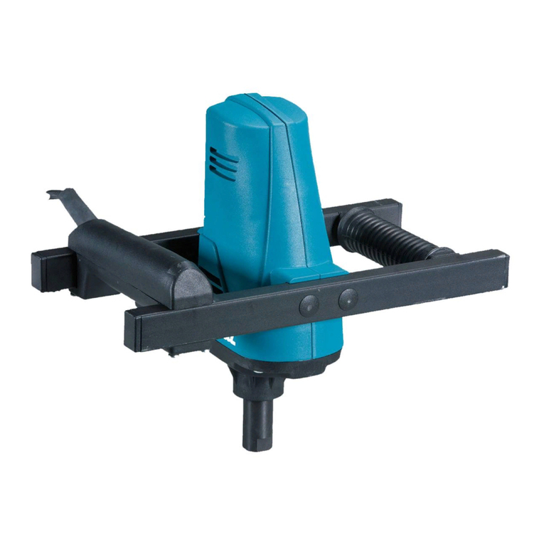
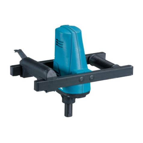
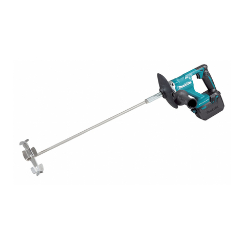
Makita UT2204 User manual

1
GB Power Mixer INSTRUCTION MANUAL
UA
✂✁✄☎✆✝☎✄
✞✆✟✄✠✡✄
☛☞✌✍✎✏✑✒☛✓
✔
✕✑✌✖✗✏✘✍✘ ✒ ☛✙
PL Mieszarka elektryczna INSTRUKCJA OBS
✚
UGI
RO Ma
✛
in
✜
de amestecat MANUAL DE INSTRUC
✢
IUNI
DE Rührgerät BEDIENUNGSANLEITUNG
HU Elektromos kever
✣
gép HASZNÁLATI KÉZIKÖNYV
SK Výkonová mieša
✤
ka NÁVOD NA OBSLUHU
CZ Míchadlo NÁVOD K OBSLUZE
UT2204

2
1
2
1 007096
1
2 007097
1
23
3 007092
1
2
3
4 007093
1
5 007101
1
2
3
6 007102
1
2
7 007103
1
2
3
8 007104
12
3
9 007098
1
10 001145
1
2
11 007099

3
ENGLISH
Explanation of general view
1-1. Lock button
1-2. Switch trigger
2-1. Indicator lamp
3-1. Hex nut
3-2. Shaft
3-3. Shaft holder
4-1. Wrench 19
4-2. Notch
4-3. Wrench 19
5-1. Mixing blade
6-1. Hex bolt
6-2. Shaft
6-3. Flat surface
7-1. Mixing blade
7-2. Shaft
8-1. Hex bolt
8-2. Shaft
8-3. Flat surface
9-1. Filter
9-2. Cover
9-3. Screwdriver
10-1. Limit mark
11-1. Screwdriver
11-2. Brush holder cap
SPECIFICATIONS
Model UT2204
No load speed (min-1) 550
Mixing blade diameter 220 mm
Overall length 929 mm
Net weight 3.7 kg
Safety class /II
• Due to our continuing programme of research and development, the specifications herein are subject to change without notice.
• Note: Specifications may differ from country to country.
ENE056-1
Intended use
The tool is intended for mixing wall materials, etc.
(except flammable materials)
ENF002-1
Power supply
The tool should be connected only to a power supply of
the same voltage as indicated on the nameplate, and
can only be operated on single-phase AC supply. They
are double-insulated in accordance with European
Standard and can, therefore, also be used from sockets
without earth wire.
ENG003-2
For European countries only
Noise and Vibration
The typical A-weighted sound pressure level is 83 dB (A).
Uncertainty is 3 dB(A).
The noise level under working may exceed 85 dB (A).
Wear ear protection.
The typical weighted root mean square acceleration
value is not more than 2.5 m/s2.
These values have been obtained according to
EN60745.
For Model UT2204
ENH101-5
EC-DECLARATION OF CONFORMITY
We declare under our sole responsibility that this
product is in compliance with the following standards of
standardized documents;
EN60745, EN55014, EN61000 in accordance with
Council Directives, 89/336/EEC, 98/37/EC.
Yasuhiko Kanzaki CE2005
000087
Director
MAKITA INTERNATIONAL EUROPE LTD.
Michigan Drive, Tongwell, Milton Keynes, Bucks MK15
8JD, ENGLAND
Responsible manufacturer:
Makita Corporation Anjo Aichi Japan
GEB001-2
SPECIFIC SAFETY RULES
DO NOT let comfort or familiarity with product
(gained from repeated use) replace strict adherence
to drill safety rules. If you use this power tool
unsafely or incorrectly, you can suffer serious
personal injury.
1. Use auxiliary handles supplied with the tool.
Loss of control can cause personal injury.
2. Hold power tools by insulated gripping
surfaces when performing an operation where
the cutting tool may contact hidden wiring or
its own cord. Contact with a "live" wire will make
exposed metal parts of the tool "live" and shock
the operator.
3. Always be sure you have a firm footing.
Be sure no one is below when using the tool in
high locations.
4. Hold the tool firmly.
5. Keep hands away from rotating parts.
6. Do not leave the tool running. Operate the tool
only when hand-held.
7. Do not touch the drill bit or the workpiece

4
immediately after operation; they may be
extremely hot and could burn your skin.
8. Some material contains chemicals which may
be toxic. Take caution to prevent dust
inhalation and skin contact. Follow material
supplier safety data.
SAVE THESE INSTRUCTIONS.
WARNING:
MISUSE or failure to follow the safety rules stated in
this instruction manual may cause serious personal
injury.
FUNCTIONAL DESCRIPTION
CAUTION:
• Always be sure that the tool is switched off and
unplugged before adjusting or checking function on
the tool.
Switch action
Fig.1
CAUTION:
• Before plugging in the tool, always check to see
that the switch trigger actuates properly and
returns to the "OFF" position when released.
To start the tool, simply pull the switch trigger. Release
the switch trigger to stop.
For continuous operation, pull the switch trigger and
then push in the lock button.
To stop the tool from the locked position, pull the switch
trigger fully, then release it.
Indicator lamp
Fig.2
The green power-ON indicator lamp lights up when the
tool is plugged to the mains. If the indicator lamp is lit but
the tool does not start even if the tool is switched ON,
the carbon brushes may be worn out, or the motor or the
switch may be defective. If the indicator lamp does not
light up, the mains cord or the indicator lamp may be
defective. When the mains cord is defective, the tool
neither starts nor lights the indicator lamp. When the
indicator lamp is defective, the tool starts without the
indicator lamp lighting up.
ASSEMBLY
CAUTION:
• Always be sure that the tool is switched off and
unplugged before carrying out any work on the
tool.
Installing shaft
Fig.3
Tighten the shaft with hex. Nut into the shaft holder as
far as the hex nut comes into contact with the holder..
Hold the notch in the shaft holder with wrench 19 so that
it cannot revolve. With the notch held so, tighten the hex
nut with another wrench 19 in the direction of arrow
Fig.4
Installing mixing blades
Fig.5
Fig.6
Insert the mixing blade into the shaft and secure it with
the hex bolt.
At this time, position it so that the top end of the hex bolt
always fits to the flat surface on the shaft and tighten the
hex bolt with the provided wrench.
When installing the mixing blades at two different
positions (which is applicable only to the mixing blades
allowed to do so), mount and secure the two mixing
blades on the flat part of the shaft with the hex bolts so
that the same surface of blades faces each other as
shown in the figure.
Fig.7
Fig.8
OPERATION
Mixing
CAUTION:
• Do not use to mix flammable material such as paint
with thinner used as solvent. Failure to do so may
cause injury.
1. Hold the rear handle of the tool with one hand and
the grip with the other hand firmly, place the
mixing blade under material fully and turn on the
tool after making sure work site safety.
2. Move the mixing blade up and down during the
mixing operation so that whole part of material
can be mixed.
3. When finishing mixing, turn off the tool, make sure
that the mixing blade has come to a complete stop,
and then pull it out of the vessel.
MAINTENANCE
CAUTION:
• Always be sure that the tool is switched off and
unplugged before attempting to perform inspection
or maintenance.
Replacing filter
Fig.9
Replace the filter regularly as the cooling efficiency of
the tool is reduced due to built-up dust or particles in
the filter.

5
Insert the slotted bit screwdriver and the like between
the tool and the cover as shown in the figure. Lift it up
just like using a shovel and remove the cover.
Replace the filter in the cover with a new one.
Reinstall the cover on the tool.
Replacing carbon brushes
Fig.10
Remove and check the carbon brushes regularly.
Replace when they wear down to the limit mark. Keep
the carbon brushes clean and free to slip in the holders.
Both carbon brushes should be replaced at the same
time. Use only identical carbon brushes.
Use a screwdriver to remove the brush holder caps.
Take out the worn carbon brushes, insert the new ones
and secure the brush holder caps.
Fig.11
To maintain product SAFETY and RELIABILITY, repairs,
any other maintenance or adjustment should be
performed by Makita Authorized Service Centers,
always using Makita replacement parts.
ACCESSORIES
CAUTION:
• These accessories or attachments are
recommended for use with your Makita tool
specified in this manual. The use of any other
accessories or attachments might present a risk of
injury to persons. Only use accessory or
attachment for its stated purpose.
If you need any assistance for more details regarding
these accessories, ask your local Makita Service Center.
• Mixing blades
• Shaft

6
✂✁✄☎✆✝✞✄
✟✠✡☛☞✌☞☞✡
✍✠
✎✏✑✏✒✓☞✠✑✠
✔✕✍✖
1-1.
✗✘✙✚✛✜✢✣
1-2.
✤ ✢✦✙✛
✧★✩★✙ ✛✪✛
2-1.
✫✛✩✦✢✪✙✛
✘ ✬ ★✙ ✛✜✢✣✛
3-1.
✭✮✚✜★✯✣✛ ✛
✯✛✰✙✛
3-2.
✱✛✲
3-3. Shaft holder
4-1.
✤✲✳✪
19
4-2.
✴✣✢✣✘✵✶
4-3.
✤✲✳✪
19
5-1.
✷★✚✙
✬✲✸
✵✩✘✹✺✧✛ ✸
6-1.
✻✢✲✜
✘✵
✹✮✚✜★✯✣ ✛ ✢✳
✯✢✲✘✧✙✢✳
6-2.
✱✛✲
6-3.
✴✲✛✚✙✛
✦✢✧✮✣✼ ✸
7-1. Mixing blade
7-2.
✱✛✲
8-1.
✻✢✲✜
✘✵
✹✮✚✜★✯✣ ✛ ✢✳
✯✢✲✘✧✙✢✳
8-2.
✱✛✲
8-3.
✴✲✛✚✙✛
✦✢✧✮✣✼ ✸
9-1.
✗✘✲✶✜✣
9-2.
✤✣★✹✙✛
9-3.
✱★✙✣✺✜✙✛
10-1.
✽✾✩✮✿✺✧✛✲✶ ✛
✧✘✬✩✘✜✙✛
11-1.
✱★✙✣✺✜✙✛
11-2.
✤✢✧✦✛✪✢✙
❀✘✜✙✢✜✣★✩✛✪✛
❁❂❃❄❅❆❄❅
❃❇❈❇❉ ❁❂ ❈ ❊❋❁❊❉❊
●❍■❏❑▲
UT2204
▼◆❖■P◗❘❙▲
❚❍❑❍❘❙❍❯❍
❚❍■ ❱
(
❚◆
-1) 550
❲◗❳❨❏❙❩
■❖❘P❳
■❑❬
❭❨◗❪❱◆❳❫❫❬
220
❨❨
❴❳❯❳❑▲❫❳
■❍◆❵❖❫❳
929
❨❨
❛❖❘❙❳
◆❳❯❳
3,7
P❯
❜❑❳❘
❝❏❭❞❏P❖
/II
•
❛❏❩❏❭
❙❏
,
❡
❍
❨❖
❫❏
❞❩❖❞❖❫❬
❢❨❍
❞❩❍❯❩❳❨❖
■❍❘❑◗■❵❏❫▲
◗
❩❍❭◆❖❙P❱
,
❫❳◆❏■❏❫◗
❙❱❙
❙❏❚❫ ◗❣
❫◗
❚❳❩❳P❙❏❩❖❘❙❖P❖
❨❍❵❱❙▲
❝❱❙❖
❭❨◗❫❏❫◗
❝❏❭
❞❍❞❏❩❏■❵❏❫❫❬
.
•
❤❩❖❨◗❙P❳
.
✐
❩◗❭❫❖❚
P❩❳❥❫❳❚
❙❏❚❫ ◗❣
❫◗
❚❳❩❳P❙❏❩❖❘❙❖P❖
❨❍❵❱❙▲
❝❱❙ ❖
❩◗❭❫❖❨❖
.
ENE056-1
❦❧♠♥♦♣qr♦♦s
t✉✈✇①②③④✉✇
⑤①⑥⑦✉⑧⑨ ④✉⑩
❶❷❸
⑦③❹❺②❻⑧✉✉❸
③⑧✇④①❹⑧❷❹❻
❶❷❸
❻⑥❼⑩✉⑧✉✉❸
✈✇❹✉
❹
✇
.
❶
. (
⑦⑧
❻⑥✉❸✇❼⑩③
⑦⑧❽③⑥✈✇⑥❾
③⑧✇④①❹⑧❷❹❻
)
ENF002-1
❿➀r❧r➁➂
➀♠➃➁r♦♦s
t✉✈✇①②③④✉✇
③⑩➄✉⑧
⑤❹❶❼❷➅⑨⑧✇⑥
❷⑥❺④
❶⑩
❶➄④①④❷⑧
✈✇①②③②
,
➆⑩
③⑧➇
✉⑧⑤①②➈②
,
⑦⑧⑦✉⑧⑨④✉②
❻
✇⑧➉❷⑥⑨➊❹
⑦
⑦⑧❻⑩❶✈ ➋❼ ⑥③⑥
❾⑧①⑧❼✇④①⑥✈✇⑥❼⑧③⑥
,
❹
❻❹✉
③⑩➄④
⑤①⑧➊➅❻⑧✇⑥
❷⑥❺④
❻❹❶
⑩❶✉ ⑩➌⑧⑦✉⑩➈⑩
❶➄④①④❷⑧
⑤④①④③❹✉✉⑩➈⑩
✈✇①②③②
.
t✉✈✇①②③④✉✇
③⑧➇
⑤⑩❶❻❹❽✉②
❹⑦⑩❷❸➊❹➅
⑦➈❹❶✉⑩
⑦
➇❻①⑩⑤④❽✈➋❼⑥③
✈✇⑧✉❶⑧①✇⑩③
❹
,
⑩✇➄④
,
③⑩➄④
⑤❹❶❼❷➅⑨⑧✇⑥✈ ❸
❶⑩
①⑩⑦④✇⑩❼
➉④⑦
❼❷④③⑥
⑦⑧⑦④③❷④✉✉❸
.
ENG003-2
➍➎➁➏➐♠
➑➁s
➐❧♣➒♦
➓➃❧➂➔♠
→➣↔
↕♣
➃➎➙❧♣➛➎s
➜⑥⑤⑩❻⑥❽
①❹❻④✉➋
⑦❻②❼⑩❻⑩➈⑩
✇⑥✈❼②
⑦⑧
❺❼⑧ ❷⑩➅
➝
❶⑩①❹❻✉➅➇
83
❶➞
(A).
➟⑩➈①❹❺✉❹✈✇➋
✈✇⑧✉⑩❻⑥✇➋
3
❶➞
(A).
➠❹❻④✉➋
❺②③②
⑤❹❶
⑨⑧✈
①⑩➉⑩✇⑥
③⑩➄④
⑤④①④❻⑥➆②❻⑧✇⑥
85
❶➞
(A).
➂❧♠➡↕ ➣➢↕r➡s
♥♣➡➂➙♣↔♠
♥♣➤♠ ➡↕ ➣
➡➁➣➤➣
.
➜⑥⑤⑩❻④
⑦❻⑧➄④✉④
✈④①④❶✉➋⑩❼❻⑧❶①⑧✇⑥⑨✉④
⑤①⑥✈❼⑩①④✉✉❸
✉④
⑤④①④❻⑥➆②➇
2,5
③
/
✈
2.
➥❹
⑦✉⑧⑨④✉✉❸
➉②❷⑥
⑩✇①⑥③⑧✉❹
❻❹❶⑤⑩❻❹❶✉⑩
❶⑩
✈✇⑧✉❶⑧①✇②
EN60745.
❿➁s
↔➂➑ r➁➎
UT2204
ENH101-5
➦➧➨➩➫➭➫➯➲➳
➵➲➦➸➺➵➲➦➻➺➼➽➲
➾➼
➚⑥
⑦⑧❸❻❷❸➇③⑩
⑤❹❶
✉⑧❺②
❻⑥❼❷➅⑨✉②
❻❹❶⑤⑩❻❹❶⑧❷➋✉❹✈✇➋
,
➆⑩
➊④❽
❻⑥①❹➉
❻❹❶⑤⑩❻❹❶⑧➇
❻⑥③⑩➈⑧ ③
✉⑧❻④❶④✉ ⑥❾
✉⑥➄⑨④
✈✇⑧✉❶⑧①✇❹❻
✉⑩①③⑧✇⑥❻✉⑩➪
❶⑩❼②③④✉✇⑧➊❹➪
;
EN60745, EN55014, EN61000
②
❻❹❶⑤⑩❻❹❶✉⑩✈✇❹
❶⑩
➶⑥①④❼✇⑥❻
➠⑧❶ ⑥
➹❻①⑩⑤⑥
89/336/EEC, 98/37/EC.
➘✈②❾❹❼⑩
➴⑧✉⑦⑧❼❹
CE2005
000087
➶⑥①④❼✇⑩①
➷✄➬➍
✄
➬✆
➍➮✁✆➮→
✆➱
✃✁
❐❦
➱➍❿
.
➚❹⑨❹➈⑧✉
-
➶①⑧❽❻
,
➜⑩✉➈❻④❷❷
,
➚❹❷✇⑩✉
-
➴④❽✉④✈
,
➈①⑧➌✈✇❻⑩
➞④❼❹✉➈④③❺⑥①
MK15 8JD,
➝❒❮❰t➘
Ï❹❶⑤⑩❻❹❶⑧❷➋✉⑥❽
❻⑥①⑩➉✉⑥❼
:
➚⑧❼❹✇⑧
➴⑩①⑤⑩①④❽❺✉
➝✉❶➄⑩
➝❹⑨❹
➘⑤⑩✉❹❸
GEB001-2
ÐÑÒÓÔ Õ Ö×
ØÙÚÖÕÔÚ
ÛÜÝÞ×ßÕ
ÓÜàØÜßÕ
✆➮
❿❐áâ❐➱ãä➍➮
♦r➑➙♣➁➂å➂
➔➂➃➂➑➀r♦♦s
♥
➛♠↔
➃♠❧➂➙➂↔
(
s➐r
♥
'
s➃➁sæ↕➏➡s
➔➎➡➁s
❧rå➣➁s ❧♦➂å➂
➃♠➐➂❧♠➡↕♣♦ ♦s
)
♥♣↔➎➡↕➏
➡➣➃➂❧➂å➂
➑➂↕❧♠↔♣♦♦s
➔❧♣➃♠➁
➙r♥➔r➐♠
➔❧♠
❧➂➙➂↕➎
♥
➑❧♠➁r↔
.
❦❧♠
➃♠➐➂❧♠➡↕♣♦♦➎
➛➏➂å➂
r➁r➐↕❧➂ ➎♦➡↕❧➣↔r♦ ↕➣
➎♥
➔➂❧➣çr♦♦s ↔
➔❧♣➃♠➁
↕r➤♦ ➎➐♠
➙r♥➔r➐♠
♣➙➂
♦♣
♥♣
➔❧♠♥♦♣qr♦♦s↔
,
â♠
↔➂➀r↕r
➂↕❧♠↔♣↕♠
➡r❧➢➂♥♦➣
↕❧♣➃↔➣
.
1.
➂❧♠➡↕ ➣➢↕r➡➏
➑➂➑♣↕➐➂ ➃♠↔♠
❧➣➐➂s↕➐♣↔♠
,
è➂

7
✂✁✄☎✆☎✝✄✞✁✟
✠
✡☛✁✄☞✌✍✎☛ ✄✍
.
✏✑✒✓✑✓
✔✕✖✑✒✕✗✘
✙✒✚✛✜✕✢✚✑✣
✢✕
✑✒✓✜✤✓✑✚✛✤
.
2.
✦☞✧
★✧✩☛✌★☎☛☛✡
☞✪✡✄
,
✂☞✧
✟✩✧✫
☞✡✬✌✆✧✭
✡☛✁✄☞✌✍✎ ☛ ✄
✍✬✎
✩☛✄☎✩✄✌★☎✄✧
✠✡
✁✫★☎☛✝
✂☞★✮✩✝
☎✪
★✯☎✁☛✧✍
✰☛✌☞ ✍
,
☛✎✪✫✡✮☛
✄☞✧✍☎ ✄✧
✎✯✎✩✄☞
✡☛✁✄☞✌✍✎☛ ✄
✠☎
✡✠✯ ✞★☎☛✡
✂★✎☞✫☛✡
☞✌✩✟✄✩
.
✱✕✖✑✓✔✑
✛
✙✒✕✜✕✢✕✤
✲✓✛✚
✙✒✚✛✜✳✢✳
✢✕
✴✴
✙✕✙✓✢✓✖✖✵
✖✓
✜✶✢✔✒✚✑✶
✤✳✑✓ ✗✳✜✶
✢✳✑✓ ✗✶
✶✖✷✑✒ ✤✳✖✑✓
✶
✤✕✸✳
✒✓✛✚✑✚
✔✕✒✚✷✑ ✜✓✹✓
✳✗✳✔✑ ✒✚ ✹✖✚✤
✷✑✒ ✤✕✤
.
3.
✺☎★✬✮✧
✍☎✭✄✎
✄★✎☞✮ ✌
✂☞✌
.
✦☞✧
★✧✩☛☎☛☛✡
★✧✁✄☛✧✫
☞✪✡✄
✂✎☞✎✩☛☎✭✄✎✁✟
,
✻
✂✡✮
✼☎✍✧
☛✡✩✽
☛✎✍☎✾
.
4.
✿✡❀☛
✄☞✧✍☎✭ ✄✎
✡☛✁✄☞✌✍✎ ☛✄
.
5.
❁✎
✄☞✩☎✭ ✄✎✁✞
☞✌✩☎✍✧
✆☎✁✄✧☛
,
✻
✪✎☞✄☎✝✄✞✁✟
.
6.
❁✎
✠☎✯✧✰☎✭✄✎
✡☛✁✄☞✌✍✎☛ ✄
✂☞☎❀✝✝✆ ✧✍
.
✦☞☎❀✝✭✄✎
✠
✡☛✁✄☞✌✍✎☛ ✄✍
✄✡✯✞✩✧
✄✮✡
,
✩✯✧
✄☞✧✍☎ ✾✄✎
✭✽
★
☞✌✩☎✫
.
7.
❁✎
✄☞✩☎✭ ✄✎✁✞
✁★✎☞✮✯☎
☎✪
✠☎✽✄★✩✧
✮☞☎✠✌
✂✡✁✯✟
✁★✎☞✮✯✡☛☛✟
;
★☛✧
✍✬ ✌✄✞
✪✌✄✧
✮ ✌✬✎
✽☎☞✟✆✧✍✧
✡
✁✂☞✧✆✧☛✧✄✧
✂✡✩✧
✰✩✡☞✧
.
8.
❂✎✟✩✡
✍☎✄✎☞✡ ☎ ✯✧
✍☎✝✄✞
✌
✁★✾✍✌
✁✩✯☎✮✡
✄✩✁✧✆☛✡
✫✡✍✡✆☛✡
☞✎✆★✧☛✧
.
❃✌✮✞✄✎
✌★☎✬ ☛✡
,
✻✪
✠☎✂✪✡✽✄✧
★✮✧✫☎☛☛✟
✂✧✯✌
✄☎
✩☛✄☎✩✄✡★
✠✡
✰✩✡☞✝
.
❂✄☞✧ ✍✌✭ ✄✎✁✟
✂☞☎★✧✯
✄✎✫ ☛✡✩ ✧
✪✎✠✂✎✩✧
★✧☞✪☛✧✩☎
✍☎✄✎☞✡ ☎ ✯✌
.
❄❅❆❇❈❉❊❋●❆
❍❈
■❏❊❄❈■❏❑
▲▼◆❖◆
:
❁P❂◗❘❙❚✿❯❁❁❱
✂☞☎★✧✯
✄✎✫ ☛✡✩✧
✪✎✠✂✎✩✧
,
☛☎★✎✮✎☛✧✫
✌
❀✡✭
✡☛✁✄☞✌✩ ❀✡❲
✠
✎✩✁✂✯✌☎✄☎❀✡❲
,
✍✬✎
✂☞✧✠★✎✁✄✧
✮
✁✎☞✭✠☛ ✽
✄☞☎★✍✌★☎☛☛✟
.
❈❳❨●❇❩❏❍❈❬
❄
■❑❏❭❇❑❨●❊ ❳❳❬
◗❃P❙P❪❁◗
:
•
❫✳✒✳✢
✒✳❴ ✗✘✜✓✖✖✵✤
✑✓
✙✳✒✳✜✶✒✔✕✘
✷✙✒✓✜✖✕✷✑✶
✶✖✷✑✒ ✤✳✖✑
,
✙✳✒✳✔✕✖✓❵✑✳✷✵
✜
✑✕✤
,
❛✕
✜✶✖
✜✚✤✔✖✳✖✚❵
✑✓
✜✶✢✔✗✘✹✳✖✚ ❵
✜✶✢
✤✳✒✳✸✶
.
❜❝❞
❡❢❣❢❤✐❥✐
.
Fig.1
◗❃P❙P❪❁◗
:
•
❫✳✒✳✢
✜✤✚✔✓✖✖✵✤
✶✖✷✑✒ ✤✳✖✑
✤✳✒✳✸
✕❦✕✜
'
✵✛✔✕✜✕
✙✳✒✳✜✶✒✑✳
,
✹✚
✔✖✕✙✔✓
✜✚✤✚✔✓✹✓
✖✕✒✤✓✗✣✖✕
✷✙✒✓❧✣✕✜ ♠
✶
✙✶✷✗✵
✜✶✢✙ ✷✔ ✓ ✖✖✵
✙✕✜✳✒✑✓♠✑✣✷✵
✜
✙✕✗✕✸ ✳✖ ✖ ✵
"
✜✚✤✔✖✳✖✕
".
♥✕❦
✜✔✗✘✹✚✑✚
✶✖✷✑✒ ✤✳✖✑
,
✙✒✕✷✑✕
✖✓✑✚✷✖✶✑✣
✔✖✕✙✔
✜✚✤✚✔✓✹✓
.
♥✕❦
✛ ✙✚ ✖✚✑✚
-
✜✶✢✙ ✷✑✶✑✣
✔✖✕✙✔
✜✚✤✚✔✓✹✓
.
♦✗✵
✢✕✜❴✕✑✒✚ ✜✓✗✕✴
✒✕❦✕✑✚
✖✓✑✚✷✖✶✑✣
✔✖✕✙✔
✜✚✤✚✔✓✹✓
,
✙✶✷✗✵
✹✕❴✕
✖✓✑✚✷✖✶✑✣
✔✖✕✙✔
✲✶✔✷✓✑✕✒✓
.
♥✕❦
✛ ✙✚✖✚✑✚
✶✖✷✑✒ ✤✳✖✑
✶✛
✛✓✲✶✔✷✕✜✓✖✚✤
✜✚✤✚✔✓✹✳✤
,
✖✓✑✚✷✖✶✑✣
✔✖✕✙✔
✜✚✤✚✔✓✹✓
✢✕
✔✶✖❧✵
✶
✜✶✢✙ ✷✑✶✑✣
✴✴
.
♣✐❣
qr
❥❤✐
❝st❢❤✐
✉r✈✐
Fig.2
✱✕✗✚
✶✖✷✑✒ ✤✳✖✑
✜✤✚✔✓✘✑✣
✢✕
✷✶✑✶
,
✛✓❴✕✒✵♠✑✣✷✵
✛✳✗✳✖✓
✶✖✢✚✔✓✑✕✒✖✓
✗✓✤✙✕✹ ✔ ✓
.
✇
✔❛✕
✶✖✢✚✔✓✑✕✒✖✓
✗✓✤✙✓
❴✕✒✚✑✣
,
✓✗✳
✶✖✷✑✒ ✤✳✖✑
✖✳
✛✓✙ ✷✔✓♠✑✣✷✵
,
✖✓✜✶✑✣
✵✔❛✕
✜✶✖
✜✶✤✔✖✳✖✚❵
,
✑✕
❧✳
✤✕✸✳
✕✛✖✓✹✓✑✚
,
❛✕
✛✖✕①✳✖✶
❴✒✓✲✶✑✕✜✶
❛✶✑✔✚
,
✓❦✕
♠
✢✳✲✳✔✑
✜
✤✕✑✕✒✶
✓❦✕
✜
✙✳✒✳✤✚✔✓✹
.
✇✔❛✕
✗✓✤✙✕✹✔✓
✶✖✢✚✔✓✑✕✒✓
✖✳
✛✓❴✕✒✵♠✑✣✷✵
,
✑✕
❧✳
✕✛✖✓✹✓♠
❛✕
♠
✢✳✲✳✔✑
✜
①
✖ ✒✶
✸✚✜✗✳✖✖✵
✓❦✕
✶✖✢✚✔✓✑✕✒✖✶❵
✗✓✤✙✕✹❧ ✶
.
②
✒✓✛✶
✢✳✲✳✔✑
①
✖ ✒✓
✸✚✜✗✳✖✖✵
✶✖✷✑✒ ✤✳✖✑
✖✳
✛✓✙ ✷✔✓♠✑✣✷✵
,
✑✓
✶✖✢✚✔✓✑✕✒✖✓
✗✓✤✙✕✹✔✓
✖✳
✛✓❴✕✒✵♠✑✣✷✵
.
②
✒✓✛✶
✢✳✲✳✔✑
✶✖✢✚✔✓✑✕✒✖✕✴
✗✓✤✙✕✹✔✚
,
✶✖✷✑✒ ✤✳✖✑
✛✓✙ ✷✔✓♠✑✣✷✵
,
✓
✶✖✢✚✔✓✑✕✒✖✓
✗✓✤✙✓
✖✳
❴✕✒✚✑ ✣
.
❏❭③④⑤❆❏ ●❩■❊❳❳❬
◗❃P❙P❪❁◗
:
•
❫✳✒✳✢
✑✚✤
,
✵✔
✛✓❵✖✵✑✚✷✣
✔✕✤✙✗✳✔✑ ✜✓ ✖✖✵✤
✶✖✷✑✒ ✤✳✖✑
,
✙✳✒✳✔✕✖✓❵✑✳✷✵
✜
✑✕✤
,
❛✕
✜✶✖
✜✚✤✔✖✳✖✚❵
✑✓
✜✶✢✔✗✘✹✳✖✚❵
✜✶✢
✤✳✒✳✸✶
.
▼⑥✉✐sr❡⑦⑧ss
❞
❡✐⑦✐
Fig.3
⑨✓✑✵❴✖✶✑✣
✜✓✗
✑✓✔✚✤
✹✚✖✕✤
,
❛✕❦
①✳✷✑✚❴✒✓✖✖✓
❴✓❵✔✓
✛✓❵
①
✗✓
✑✒✚✤✓✹
✜✓✗✓
✢✕
✙✕✒✓
✑✓
✑✕✒✔✖ ✗✓✷✣
✑✒✚✤✓✹✓
.
⑩✒✚✤✓❵✑✳
✙✒✕✒✶✛✣
✜
✑✒✚✤✓✹✶
✜✓✗✓
✛✓
✢✕✙✕✤✕❴✕✘
✔✗✘✹✓
❶
19,
❛✕❦
✜✶✖
✖✳
✕❦✳✒✑✓✜✷✵
.
⑩✒✚✤✓✘✹✚
✙✒✕✒✶✛✣
✑✓✔✚✤
✹✚✖✕✤
,
✛✓✑✵❴✖✶✑✣
①
✳✷✑✚❴✒✓✖✖
❴✓❵✔
✶✖①
✚✤
✔✗✘✹✳✤
❶
19
✖✓✙✒✵✤✔
,
❛✕
✜✔✓✛✓✖✚❵
✷✑✒✶✗✔✕✘
.
Fig.4
▼⑥✉✐sr❡⑦⑧ss
❞
t❢⑥❤✐
t⑦❞
❷
❣❝❸❹
❡✐ss
❞
Fig.5
Fig.6
❺
✓✢✶✖✣✑✳
✢✚✷✔
✢✗✵
✛✤✶①
✜✓ ✖ ✖ ✵
✖✓
✜✓✗
✑✓
✛✓✔✒✶✙✶✑✣
❵✕❴✕
①✳✷✑✚❴✒✓✖✖✚✤
❦✕✗✑✕✤
.
⑩✳✙✳✒
❵✕❴✕
✷✗✶✢
✒✕✛✑✓①✜✓✑✚
✑✓✔
,
❛✕❦
✜✳✒❻✖✶❵
✔✶✖✳❧✣
❦✕✗✑✓
✶✛
①
✳✷✑✚❴✒✓✖✖✕✘
❴✕✗✶✜✔✕✘
✛✓✜✸✢✚
✙✒✚✗✵❴✓ ✜
✢✕
✙✗✓✷✔✕✴
✙✕✜✳✒
❻✖✶
✖✓
✜✓✗
,
✓
✑✓✔✕✸
✛✓✑✵❴✖ ✑✚
❦✕✗✑
✶✛
①
✳✷✑✚❴✒✓✖✖✕✘
❴✕✗✶✜✔✕✘
✛✓
✢✕✙✕✤✕❴✕✘
✔✗✘✹✓
,
❛✕
✢✕✢✓♠✑✣✷✵
.
❫✶✢
✹✓✷
✜✷✑✓✖✕✜✗✳✖✖✵
✢✚✷✔✶✜
✢✗✵
✛✤✶①✜✓✖✖✵
✢✜✕❻
✒✶✛✖✚
❻
✙✕✗✕✸ ✳✖ ✖ ✵
❻
(
❧✳
✷✑✕✷ ♠✑ ✣✷✵
✑✶✗✣✔✚
✑✚
❻
✢✚✷✔✶✜
,
✢✗✵
✵✔✚
❻
❧✳
✢✕✛✜✕✗✳✖✕
✒✕❦✚✑✚
)
✷✗✶✢
✜✷✑✓✖✕✜✚✑✚
✑✓
✛✓✔✒✶✙✚✑✚
✢✜✓
✢✚✷✔✓
✢✗✵
✛✤✶①✜✓✖✖✵
✖✓
✙✗✓✷✔✶❵
✹✓✷✑✚✖✶
✜✓✗
✛✓
✢✕✙✕✤✕❴✕✘
❦✕✗✑✶✜
✶✛
①
✳✷✑✚❴✒✓✖✖✚✤✚
❴✕✗✶✜✔✓✤✚
,
❛✕❦
✕✢✖✕✶✤✳✖✖✶
✙✕✜✳✒
❻✖✶
✢✚✷✔✶✜
❦ ✗✚
✖✓✙✒✓✜✗✳✖✶
✕✢✖✳
✢✕
✕✢✖✕❴✕
,
✵✔
✙✕✔✓✛✓✖✕
✖✓
✤✓✗✘✖✔
.
Fig.7
Fig.8

8
✂✁✄☎✁✆✝✞ ✞✟
✠✡☛☞✌✍✎✏✏✑
✒✓✔✕✔✖✗✒
:
•
✘✙✚✛✜✛✢✣✢✛
✤ ✦✧★✩✙✪✫
✤✙✬ ✫✭✪✦
✙✪✣✜✦✙✮ ✫
✪✙✯✦
✰✯
✱✙✜✚✫
✤
✜✛✤✲✫✢✢✫✯✙ ✫
.
✳✣✩✫✯✛✢✙✢✢✰
✴✦✵✶
★ ✛✩✫
✛✷✣
✸✜✫✤✩✣✭✪✫
✹✛
✪✜✙✩
.
1.
✺✜✫ ✙✬✪✣
✤✙✹✢✻
✜★✲✯★
✦✢✭✪✜★ ✣✢ ✪✙
✛✹✢✦✵✻
✜★✯✛✻
,
✙
✹✜★✼✛✻
✜★✯✛✻
✦✴✢✛
✪✜✫ ✙✬ ✪✣
✤✙
✜★✯✛✰✪✽
,
✸✛✩✢✦✭✪✻
✤✙✢★✜✦✪✽
✹✫✭✯
✹✮✰
✤ ✦✧★✩✙ ✢✢✰
✩
✙✪✣✜✦✙✮
✪✙
★✩✦ ✯✢✦✪✽
✦✢✭✪✜★ ✣✢ ✪
,
✸✦✭✮✰
✪✛✼✛
,
✰✯
✸✣✜✣✯✛✢✙✵✪✣✭✽
★
✚✣✤✸✣✲ ✢ ✛✭✪✦
✜✛✚✦✪
.
2.
✾✣✜✣✭★✩✙✬ ✪✣
✿ ✦✧★✻✲✫✬
✹✫✭✯
★✩✣✜✿
✪✙
✩✢✫✤
✸✦✹
✲✙✭
✤ ✦✧★✩✙ ✢ ✢✰
,
❀✛✚
✙✪✣✜✦✙✮
✸✛✩✢✦✭✪✻
✸✣✜✣ ✦✧✙✩✭✰
.
3.
✳✙✸✜✫✯✦✢✴✦
✤ ✦✧★✩✙ ✢ ✢✰
✭✮✦✹
✩✫ ✯✢★✪✫
✦✢✭✪✜★ ✣✢✪
,
✤✙✷✹✙✪✫
✹✛✯✫
✤ ✦✧★✻✲✫✬
✹✫✭✯
✸✛✩✢✦✭✪✻
✤★✸✫✢✫✪✽✭✰
,
✙
✸✛✪✦
✩✫✪✰✼✢★✪✫
✬✛✼✛
✤
✭✛✭★✹✙
.
✄
❁❂✞
❃❄✞
❁
☎
❅
✁
❆✆
❇☎✝✆✝✞✞✟
✒✓✔✕✔✖✗✒
:
•
✾✣✜✣✹
✪✫
,
✰✯
✛✼✮✰✢★✪✫
✦✢✭✪✜★ ✣✢✪
,
✙✚✛
✩✫✯✛✢✙✪✫
✜✣ ✛✢✪
,
✸✣✜✣✯✛✢✙✬✪✣✭✰
,
❀✛
✩✦✢
✩✫ ✯✢✣✢✫✬
✪✙
✩✦✹✯✮✻✲✣✢✫✬
✩✦✹
✣✜✣✷✦
.
✠✎✡☛✏✎
❈☛❉❊❋●✎
Fig.9
❍✣✼ ★✮✰✜✢✛
✤✙ ✦✢✻✬✪✣
✱✦✮✽✪✜
,
✛✭✯✦✮✽✯✫
✣✱✣✯✪✫✩✢✦✭✪✽
✛✿✛✮✛✹✷★✩✙✢✢✰
✦✢✭✪✜★ ✣✢✪✙
✿✤✢✫✷★✵✪✽✭✰
✲✣✜✣✤
✸✫✮
✙✚✛
✲✙✭✪✯✫
,
❀✛
✢✙✯✛✸✫✲✫✮✫✭✽
★
✱✦✮✽✪✜✦
.
■✭✪✙✩✪✣
✩✫✯✜★✪✯★
✦✤
✧✮✦✴✛✩✙✢✫
✢✙✯✛✢✣✲✢✫✯✛
✙✚✛
✸✛✹✦✚✢✫✬
✸✜✣✹ ✣✪
✦✷
✦✢✭✜★ ✣✢✪✛
✪✙
✯✜✫✧✯✛✻
,
✰✯
✸✛✯✙✤✙✢✛
✢✙
✙✮✻✢✯★
.
✾✦✹✢✦ ✦✪✽
✯✜✫✧✯★
,
✸✦✹✲✣✸✫✩✧✫
✶✶
,
✪✙
✤✢✦ ✦✪✽
✯✜✫✧✯★
.
✘✙ ✦✢✦✪✽
✱✫✮✽✪✜
✩
✯✜✫✧✴✦
✢✙
✢✛✩✫✬
.
■✭✪✙✢✛✩✦✪✽
✯✜✫✧✯★
✢✙✤✙✹
✢✙
✦✢✭✪✜★ ✣✢✪
.
✠✎✡☛✏✎
✍
❏❑
☛❉❊✏
▲▼
◆
☛❋
❖✌
Fig.10
❍✣✼ ★✮✰✜✢✛
✤✢✦ ✙✬✪✣
✪✙
✸✣✜✣✩✦✜✰✬ ✪✣
✩★✼✦✮✽✢✦
❀✦✪✯✫
.
✘✙ ✦✢✻✬✪✣
✶✿
,
✯✛✮ ✫
✤✢✛✭
✭✰✼✙✵
✼✜✙✢✫✲✢✛✶
✩✦✹ ✦✪✯✫
.
■★✼✦✮✽✢✦
❀✦✪✯✫
✸✛✩✫✢✢✦
✚★✪✫
✲✫✭✪✫ ✫
✪✙
✩✦✮✽✢✛
✜★✿✙✪✫✭✽
★
❀✦✪✯✛✪✜✫ ✙✲✙✿
.
P
✹✢✛✲✙✭✢✛
✪✜✣✚✙
✤✙ ✦✢✻✩✙✪✫
✛✚✫✹✩✦
✩★✼✦✮ ✽✢✦
❀✦✪✯✫
.
■✫✯✛✜✫✭✪✛✩★✬ ✪✣
✮✫✧✣
✛✹✢✙✯✛✩✦
✩★✼✦✮ ✽✢✦
❀✦✪✯✫
.
◗
✮✰
✩✫✹✙✮✣✢✢✰
✯✛✩✸✙✲✯✦✩
❀✦✪✯✛✪✜✫ ✙✲✦✩
✯✛✜✫✭✪★✬✪✣✭✽
✩✫✯✜★✪✯✛✻
.
■✫✹✙✮✦✪✽
✤✢✛✧✣✢✦
✩★✼✦✮✽✢✦
❀✦✪✯✫
,
✩✭✪✙ ✩✪✣
✢✛✩✦
✪✙
✤✙✯✜✦✸✦✪✽
✯✛✩✸✙✲✯✫
❀✦✪✯✛✪✜✫ ✙✲✦✩
.
Fig.11
◗
✮✰
✪✛✼✛
,
❀✛✚
✸✦✹✪✜✫ ★✩✙✪✫
❘❙
✘✾❙❚❯
✪✙
✳
❱◗❲❳ ✳
❲❨
✺
❩
,
✜✣ ✛✢✪
,
✪✣✿✢✦ ✲✢✣
✛✚✭✮★✼✛✩★✩✙✢✢✰
✙✚✛
✜✣✼★✮✻✩✙✢✢✰
✙✻✪✽
✩✫✯✛✢★✩✙✪✫
★✸✛✩✢✛✩✙✷✣✢✦
✴✣✢✪✜✫
✛✚✭✮★✼✛✩★✩✙✢✢✰
"
❬
✙✯✦✪✙
",
✹✣
✩✫✯✛✜✫✭✪✛✩★✻✪✽✭✰
✮✫✧✣
✭✪✙✢✹✙✜✪✢ ✦
✤✙✸✲✙✭✪✫✢✫
"
❬
✙✯✦✪✙
".
☎✁✞❭❁✞✞✟
✒✓✔✕✔✖✗✒
:
•
❪✣
✛✭✢✙❀✣✢✢✰
✙✚✛
✸✜✫✮✙✹✹✰
✜✣✯✛ ✣✢✹✛✩✙✢✛
✹✮✰
✩✫✯✛✜✫✭✪✙✢✢✰
✤
✦✢✭✪✜★ ✣✢✪✙ ✫
"
❬
✙✯✦✪✙
",
❀✛
✛✸✫✭✙✢✦
✩
✦✢✭✪✜★✯✴✦✶
✤
✣✯✭✸✮★✙✪✙✴✦✶
.
■✫✯✛✜✫✭✪✙✢✢✰
✰✯✛✼✛✭✽
✦✢✧✛✼✛
✛✭✢✙❀✣✢✢✰
✙✚✛
✸✜✫✮✙✹✹✰
✛✷✣
✭✸✜✫✲✫✢✫✪✫
✪✜✙✩ ★✩✙✢✢✰
.
P✭✢✙❀✣✢✢✰
✙✚✛
✸✜✫✮✙✹✹✰
✭✮✦✹
✩✫✯✛✜✫✭✪✛✩★✩✙✪✫
✮✫✧✣
✤✙
✸✜✫✤✢✙✲✣✢✢✰
.
❯
✜✙✤ ✦
✢✣✛✚✿✦✹✢✛✭✪✦
,
✛✪✜✫ ✙✪✫
✹✛✸✛ ✛✼★
✩
✚✦✮✽✧
✹✣✪✙✮✽✢✛ ★
✛✤✢✙✬✛ ✮ ✣✢✢✦
✤
✛✭✢✙❀✣✢✢✰
✤✩✣✜✪✙✬✪✣✭✽
✹✛
✦✭✴✣✩✛✼✛
❨✣✜✩✦✭✢✛✼✛
✴✣✢✪✜★
"
❬
✙✯✦✪✙
".
•
◗✫✭✯✫
✹✮✰
✤ ✦✧★✩✙✢✢✰
•
■✙✮

9
POLSKI
Obja
✁
nienia do widoku ogólnego
1-1. Przycisk blokuj
cy
1-2. Spust prze
✂
cznika
2-1. Kontrolka
3-1. Nakr
✄
tka sze
☎
ciok
tna
3-2. Trzonek mieszad
✂
a
3-3. Uchwyt
4-1. Klucz 19
4-2. Naci
✄
cie
4-3. Klucz 19
5-1. Mieszad
✂
o
6-1.
✆
ruba sze
☎
ciok
tna
6-2. Trzonek mieszad
✂
a
6-3. P
✂
aska powierzchnia
7-1. Mieszad
✂
o
7-2. Trzonek mieszad
✂
a
8-1.
✆
ruba sze
☎
ciok
tna
8-2. Trzonek mieszad
✂
a
8-3. P
✂
aska powierzchnia
9-1. Filtr
9-2. Pokrywa
9-3.
✆
rubokr
✄
t
10-1. Znak ograniczenia
11-1.
✆
rubokr
✄
t
11-2. Pokrywka uchwytu szczotki
SPECYFIAKCJE
Model UT2204
Pr
✝
dko
✞✟
bez obci
✠✡
enia (min-1) 550
☛
rednica mieszad
☞
a 220 mm
D
☞
ugo
✞✟
ca
☞
kowita 929 mm
Ci
✝✡
ar netto 3,7 kg
Klasa bezpiecze
✌
stwa /II
• W zwi
✠
zku ze stale prowadzonym przez nasz
✠
firm
✝
programem badawczo-rozwojowym, niniejsze specyfikacje mog
✠
ulec zmianom
bez wcze
✞
niejszego powiadomienia.
• Uwaga: Specyfikacje mog
✠
ró
✡
ni
✟
si
✝
w zale
✡
no
✞
ci od kraju.
ENE056-1
Przeznaczenie
Narz
✍
dzie jest przeznaczone do mieszania ró
✎
nych
materia
✏
ów nak
✏
adanych na
✑
ciany itp. (za wyj
✒
tkiem
materia
✏
ów
✏
atwopalnych).
ENF002-1
Zasilanie
Elektronarz
✍
dzie mo
✎
e by
✓
pod
✏✒
czane jedynie do
zasilania o takim samym napi
✍
ciu jakie okre
✑
la tabliczka
znamionowa i mo
✎
e by
✓
uruchamiane wy
✏✒
cznie przy
zasilaniu jednofazowym pr
✒
dem zmiennym. Przewody
s
✒
podwójnie izolowane zgodnie z Normami
Europejskimi i dlatego mog
✒
by
✓
pod
✏✒
czone do
gniazdek bez przewodu uziemiaj
✒
cego.
ENG003-2
Tylko dla krajów europejskich
Ha
✔
as i drgania
Normalne ci
✑
nienie akustyczne na poziomie A wynosi 83
dB (A).
B
✏✒
d pomiaru wynosi 3 dB(A).
Poziom ha
✏
asu podczas pracy elektronarz
✍
dzia mo
✎
e
przewy
✎
sza
✓
85 dB (A).
Nosi
✕
ochronniki s
✔
uchu
Typowa
✑
rednia wa
✎
ona warto
✑✓
skuteczna
przyspieszenia nie przekracza 2.5 m/s 2.
Warto
✑
ci te uzyskano zgodnie z EN60745.
Dla modelu UT2204
ENH101-5
DEKLARACJA ZGODNO
✖
CI Z NORMAMI WE
Deklarujemy, na nasz
✒
wy
✏✒
czn
✒
odpowiedzialno
✑✓
,
✎
e
niniejszy produkt jest zgodny z nast
✍
puj
✒
cymi normami
dokumentów normalizacyjnych;
EN60745, EN55014, EN61000 zgodnie z Dyrektywami
Rady, 89/336/EEC, 98/37/EC.
Yasuhiko Kanzaki CE2005
000087
Dyrektor
MAKITA INTERNATIONAL EUROPE LTD.
Michigan Drive, Tongwell, Milton Keynes, Bucks MK15
8JD, ENGLAND (ANGLIA)
Producent odpowiedzialny:
Makita Corporation Anjo Aichi Japan (Japonia)
GEB001-2
Szczególne zasady
bezpiecze
✗
stwa
NIE DOPU
✘
CI
✙
, aby dobre obeznanie i
przyzwyczajenie do wyrobu (zdobyte przez cz
✚
ste
u
✛
ytkowanie) zast
✜
pi
✔
o
✢
cis
✔
e przestrzeganie zasad
bezpiecze
✣
stwa. Poprzez u
✛
ytkowanie niniejszego
elektronarz
✚
dzia w sposób niebezpieczny lub
nieprawid
✔
owy, mo
✛
na dozna
✕
powa
✛
nych obra
✛
e
✣
cia
✔
a.
1. Stosowa
✕
uchwyty pomocnicze przewidziane
dla elektronarz
✚
dzia. Brak kontroli mo
✎
e
spowodowa
✓
obra
✎
enia cia
✏
a.
2. Podczas wykonywania pracy narz
✚
dziem
tn
✜
cym, trzyma
✕
elektronarz
✚
dzie za
izolowane powierzchnie uchwytów, poniewa
✛
ostrze narz
✚
dzia mo
✛
e natrafi
✕
na przewód
ukryty w materiale lub zetkn
✜✕
si
✚
z
przewodem zasilania. Kontakt z przewodem pod

10
napi
✁
ciem spowoduje przep
yw pr
✂
du do
metalowych zewn
✁
trznych cz
✁✄
ci
elektronarz
✁
dzia i pora
☎
enie operatora.
3. Zapewni
✆
sta
✝
e pod
✝
o
✞
e.
Upewni
✆
si
✟
, czy nikt nie znajduje si
✟
poni
✞
ej
miejsca pracy na wysoko
✠
ci.
4. Trzyma
✆
narz
✟
dzie w sposób niezawodny.
5. Trzyma
✆
r
✟
ce z dala od cz
✟✠
ci obrotowych.
6. Nie pozostawia
✆
za
✝✡
czonego elektronarz
✟
dzia.
Mo
✞
na uruchomi
✆
elektronarz
✟
dzie tylko
wtedy, gdy jest trzymane w r
✟
kach.
7. Nie dotyka
✆
ko
☛
cówki wiert
✝
a lub cz
✟✠
ci
obrabianej bezpo
✠
rednio po operacji; mog
✡
one by
✆
bardzo gor
✡
ce i przypali
✆
skór
✟
.
8. Niektóre materia
✝
y zawieraj
✡
substancje
chemiczne, które mog
✡
by
✆
toksyczne. Unika
✆
wdychania i kontaktu ze skór
✡
. Przestrzega
✆
przepisów bezpiecze
☛
stwa podanych przez
dostawc
✟
materia
✝
ów.
ZACHOWA
☞
INSTRUKCJE
OSTRZE
✌
ENIE:
NIEPRAWID
✍
OWE STOSOWANIE lub
nieprzestrzeganie zasad bezpiecze
☛
stwa
okre
✠
lonych w niniejszej instrukcji obs
✝
ugi mo
✞
e
spowodowa
✆
powa
✞
ne obra
✞
enia cia
✝
a.
OPIS DZIA
✎
ANIA
UWAGA:
• Przed rozpocz
✁
ciem regulacji i sprawdzania
dzia
ania elektronarz
✁
dzia, nale
☎
y upewni
✏
si
✁
, czy
jest ono wy
✂
czone i nie pod
✂
czone do sieci.
W
✑✒
czanie
Rys.1
UWAGA:
• Przed pod
✂
czeniem elektronarz
✁
dzia do sieci
zawsze sprawdza
✏
czy spust w
✂
cznika dzia
a
poprawnie i wraca do pozycji "OFF" po zwolnieniu.
W celu uruchomienia elektronarz
✁
dzia nale
☎
y nacisn
✂✏
na spust prze
✂
cznika. Zwolni
✏
spust prze
✂
cznika, aby
wy
✂
czy
✏
elektronarz
✁
dzie.
Dla uruchomienia trybu pracy ci
✂
g
ej, nacisn
✂✏
spust
prze
✂
cznika, a nast
✁
pnie wcisn
✂✏
przycisk blokuj
✂
cy.
Do zatrzymania elektronarz
✁
dzia pracuj
✂
cego w trybie
ci
✂
g
ym, nale
☎
y nacisn
✂✏
spust prze
✂
cznika do oporu, a
nast
✁
pnie zwolni
✏
go.
Kontrolka
Rys.2
Zielona kontrolka zasilania zapala si
✁
w momencie
pod
✂
czenia narz
✁
dzia do zasilania. Je
☎
eli kontrolka jest
zapalona, ale narz
✁
dzia nie mo
☎
na uruchomi
✏
, wówczas
mamy do czynienia z zu
☎
yciem szczotek b
✂
d
✓
uszkodzeniem silnika albo prze
✂
cznika. Je
☎
eli kontrolka
nie zapala si
✁
, uszkodzony jest przewód zasilaj
✂
cy albo
sama kontrolka jest przepalona. W przypadku
uszkodzenia przewodu zasilaj
✂
cego nie mo
☎
na
uruchomi
✏
narz
✁
dzia i kontrolka nie
✄
wieci si
✁
. Gdy
kontrolka jest przepalona, narz
✁
dzie mo
☎
na uruchomi
✏
,
ale kontrolka nie
✄
wieci si
✁
.
MONTA
✔
UWAGA:
• Przed wykonywaniem jakichkolwiek czynno
✄
ci na
elektronarz
✁
dziu nale
☎
y upewni
✏
si
✁
, czy jest ono
wy
✂
czone i nie pod
✂
czone do sieci.
Monta
✕
trzonka mieszad
✑
a
Rys.3
Wkr
✁
ci
✏
trzonek mieszad
a z nakr
✁
tk
✂
sze
✄
ciok
✂
tn
✂
do
oporu do uchwytu mieszad
a.
Przytrzyma
✏
kluczem 19 uchwyt mieszad
a w miejscu
naci
✁
cia w taki sposób, aby si
✁
nie obraca
.
Przytrzymuj
✂
c uchwyt, za pomoc
✂
drugiego klucza 19
dokr
✁✏
nakr
✁
tk
✁
sze
✄
ciok
✂
tn
✂
obracaj
✂
c klucz w
kierunku strza
ki.
Rys.4
Monta
✕
mieszade
✑
Rys.5
Rys.6
Nasu
✖
mieszad
o na trzonek i zablokuj je
✄
rub
✂
sze
✄
ciok
✂
tn
✂
.
Mieszad
o nale
☎
y ustawi
✏
w taki sposób, aby ko
✖
cówka
✄
ruby sze
✄
ciok
✂
tnej trafi
a na p
ask
✂
powierzchni
✁
trzonka, a
✄
rub
✁
sze
✄
ciok
✂
tn
✂
dokr
✁
ci
✏
znajduj
✂
cym si
✁
w zestawie kluczem.
W przypadku monta
☎
u mieszade
w dwóch ró
☎
nych
pozycjach (co jest mo
☎
liwe tylko w przypadku mieszade
do tego przystosowanych) nale
☎
y je przymocowa
✏
na
p
askiej powierzchni trzonka blokuj
✂
c
✄
rubami
sze
✄
ciok
✂
tnymi. Mieszad
a ustawi
✏
w taki sposób, aby te
same powierzchnie
opatek by
y zwrócone ku sobie, jak
pokazano na rysunku.
Rys.7
Rys.8
DZIA
✎
ANIE
Mieszanie
UWAGA:
• Nie wolno stosowa
✏
do mieszania materia
ów
atwopalnych, jak farba z rozcie
✖
czalnikiem
u
☎
ywanym jako rozpuszczalnik. Niestosowanie si
✁
do tej zasady mo
☎
e spowodowa
✏
obra
☎
enia.
1. Chwyci
✏
mocno narz
✁
dzie jedn
✂
r
✁
k
✂
za r
✁
koje
✄✏
tyln
✂
, a drug
✂
– za uchwyt, zanurzy
✏
mieszad
o
ca
kowicie w materiale a nast
✁
pnie - po
sprawdzeniu bezpiecze
✖
stwa w miejscu pracy -
w
✂
czy
✏
narz
✁
dzie.

11
2. Podczas operacji mieszania nale
✁
y porusza
mieszad
✂
em w gór
✄
i w dó
✂
, aby ca
✂
o
☎
materia
✂
u
zosta
✂
a dobrze wymieszana.
3. Po zako
✆
czeniu mieszania narz
✄
dzie nale
✁
y
wy
✂✝
czy
, sprawdzi
, czy mieszad
✂
o zatrzyma
✂
o
si
✄
ca
✂
kowicie, i dopiero wówczas wyci
✝
gn
✝
z
pojemnika.
KONSERWACJA
UWAGA:
• Przed wykonywaniem kontroli i konserwacji nale
✁
y
si
✄
zawsze upewni
, czy elektronarz
✄
dzie jest
wy
✂✝
czone i nie pod
✂✝
czone do sieci.
Wymiana filtra
Rys.9
Filtr nale
✁
y regularnie wymienia
, poniewa
✁
nagromadzony w filtrze py
✂
i zanieczyszczenia mog
✝
obni
✁
a
skuteczno
☎
ch
✂
odzenia narz
✄
dzia.
Pomi
✄
dzy narz
✄
dzie a pokryw
✄
w
✂
o
✁
y
☎
rubokr
✄
t p
✂
aski
lub podobny przyrz
✝
d, jak pokazano na rysunku.
✞
ci
✝
gn
✝
pokryw
✄
podwa
✁
aj
✝
c j
✝
☎
rubokr
✄
tem.
Wymieni
filtr w pokrywie na nowy.
Ponownie zamontowa
pokryw
✄
w narz
✄
dziu.
Wymiana szczotek w
✟
glowych
Rys.10
Systematycznie wyjmowa
i sprawdza
szczotki
w
✄
glowe. Wymienia
je, gdy ich zu
✁
ycie si
✄
ga znaku
granicznego. Szczotki powinny by
czyste i
✂
atwo
wchodzi
w uchwyty. Nale
✁
y wymienia
obydwie
szczotki jednocze
☎
nie. Stosowa
wy
✂✝
cznie identyczne
szczotki w
✄
glowe.
Do wyj
✄
cia pokrywek uchwytów szczotek u
✁
ywa
☎
rubokr
✄
tu. Wyj
✝
zu
✁
yte szczotki w
✄
glowe, w
✂
o
✁
y
nowe i zabezpieczy
pokrywkami uchwytów szczotek.
Rys.11
Dla zachowania BEZPIECZE
✠
STWA i
NIEZAWODNO
✞
CI wyrobu, naprawy oraz inne prace
konserwacyjne i regulacyjne powinny by
wykonywane
przez Autoryzowane Centra Serwisowe Makita,
wy
✂✝
cznie przy u
✁
yciu cz
✄☎
ci zamiennych Makita.
AKCESORIA (WYPOSA
✡
ENIE
DODATKOWE)
UWAGA:
• Zaleca si
✄
stosowanie wymienionych akcesoriów i
dodatków razem z elektronarz
✄
dziem Makita
opisanym w niniejszej instrukcji. Stosowanie
jakichkolwiek innych akcesoriów i dodatków mo
✁
e
stanowi
ryzyko uszkodzenia cia
✂
a. Stosowa
akcesoria i dodatki w celach wy
✂✝
cznie zgodnych z
ich przeznaczeniem.
W razie potrzeby, wszelkiej pomocy i szczegó
✂
owych
informacji na temat niniejszych akcesoriów udziel
✝
Pa
✆
stwu lokalne Centra Serwisowe Makita.
• Mieszad
✂
a
• Trzonek mieszad
✂
a

12
ROMÂN
✁
Explicitarea vederii de ansamblu
1-1. Buton de blocare
1-2. Tr
gaciul întrerup
torului
2-1. Lamp
indicatoare
3-1. Piuli
✂
hexagonal
3-2. Ax
3-3. Shaft holder
4-1. Cheie de 19
4-2. Crest
tur
4-3. Cheie de 19
5-1. Palet
malaxoare
6-1.
✄
urub cu cap hexagonal
6-2. Ax
6-3. Suprafa
✂
plan
7-1. Palet
malaxoare
7-2. Ax
8-1.
✄
urub cu cap hexagonal
8-2. Ax
8-3. Suprafa
✂
plan
9-1. Filtru
9-2. Capac
9-3.
✄
urubelni
✂
10-1. Marcaj limit
11-1.
✄
urubelni
✂
11-2. Capacul suportului pentru perii
SPECIFICA
☎
II
Model UT2204
Tura
✆
ia în gol (min-1) 550
Diametrul paletei malaxoare 220 mm
Lungime total
✝
929 mm
Greutate net
✝
3,7 kg
Clasa de siguran
✆✝
/II
• Datorit
✝
programului nostru continuu de cercetare
✞
i dezvoltare, caracteristicile pot fi modificate f
✝
r
✝
o notificare prealabil
✝
.
• Not
✝
: Specifica
✆
iile pot varia în func
✆
ie de
✆
ar
✝
.
ENE056-1
Destina
✟
ia de utilizare
Ma
✠
ina este destinat
✡
amestec
✡
rii materialelor de
zid
✡
rie etc. (exceptând materialele inflamabile).
ENF002-1
Surs
☛
de alimentare
Ma
✠
ina se va alimenta de la o surs
✡
de curent alternativ
monofazat, cu tensiunea egal
✡
cu cea indicat
✡
pe
pl
✡
cu
☞
a de identificare a ma
✠
inii. Având dubl
✡
izola
☞
ie,
conform cu Standardele Europene, se poate conecta la
o priz
✡
de curent f
✡
r
✡
contacte de împ
✡
mântare.
ENG003-2
Doar pentru
✟☛
rile europene
Zgomot
✌
i vibra
✟
ii
Puterea acustic
✡
la func
☞
ionarea în gol este de 83 dB (A).
Varia
☞
ia posibil
✡
este de 3 dB(A).
Nivelul de zgomot în timpul lucrului poate dep
✡✠
i 85 dB
(A).
Purta
✟
i antifoane.
Valoarea accelera
☞
iei vibra
☞
iilor nu dep
✡✠
e
✠
te 2.5m/s 2.
Aceste valori sunt în conformitate cu EN60745.
Pentru modelul UT2204
ENH101-5
CE-DECLARA
✍
IE DE CONFORMITATE
Declar
✡
m pe propria r
✡
spundere c
✡
acest produs este în
conformitate cu urm
✡
toarele standarde
✠
i reglement
✡
ri;
EN60745, EN55014, EN61000 conform cu Directivele
Consiliului, 89/336/EEC, 98/37/EC.
Yasuhiko Kanzaki CE2005
000087
Director
MAKITA INTERNATIONAL EUROPE LTD.
Michigan Drive, Tongwell, Milton Keynes, Bucks MK15
8JD, ANGLIA
Produc
✡
tor:
Makita Corporation Anjo Aichi Japan
GEB001-2
REGULI SPECIALE DE
SIGURAN
☎✎
Familiarizarea cu aceast
☛
ma
✌
in
☛
(generat
☛
de
utilizarea îndelungat
☛
) nu poate suplini respectarea
strict
☛
a acestor reguli de siguran
✟☛
. Dac
☛
folosi
✟
i
ma
✌
ina incorect, este posibil s
☛
suferi
✟
i v
☛
t
☛
m
☛
ri
grave.
1. Folosi
✟
i mânerele auxiliare furnizate cu ma
✌
ina
Pierderea controlului poate cauza v
✡
t
✡
marea
personal
✡
.
2. Sus
✟
ine
✟
i ma
✌
ina de suprafe
✟
ele izolate atunci
când efectua
✟
i o opera
✟
iune în care ma
✌
ina de
t
☛
iat poate intra în contact cu cabluri ascunse
sau cu propriul cablu de alimentare.
Contactul cu un cablu aflat sub tesniune va face
ca piesele de metal s
✡
fie parcurse de curent, iar
operatorul se va electrocuta.
3. P
☛
stra
✟
i-v
☛
echilibrul.
Asigura
✟
i-v
☛
c
☛
nu se afl
☛
nimeni dedesubt
atunci când folosi
✟
i ma
✌
ina la în
☛
l
✟
ime.
4.
✏
ine
✟
i bine ma
✌
ina
5. Nu atinge
✟
i piesele în mi
✌
care.
6. Nu l
☛
sa
✟
i ma
✌
ina în func
✟
iune. Folosi
✟
i ma
✌
ina
numai când o
✟
ine
✟
i cu mâinile
7. Nu atinge
✟
i burghiul sau piesa de lucru imediat
dup
☛
opera
✟
iune; acestea pot fi fierbin
✟
i
✌
i v
☛

13
pot cauza arsuri
8. Unele materiale con
✁
in substan
✁
e chimice care
pot fi toxice. Ave
✁
i grij
s
nu inhala
✁
i praful
✂
i
evita
✁
i contactul cu pielea. Respecta
✁
i
instruc
✁
iunile de siguran
✁
ale furnizorului
P
✄
STRA
☎
I ACESTE
INSTRUC
☎
IUNI
AVERTISMENT:
Utilizarea necorespunz
toare sau nerespectarea
regulilor din manualul de instruc
✁
iuni poate cauza
v
t
m
ri personale grave
DESCRIERE FUNC
☎
IONAL
✄
ATEN
✆
IE:
• Asigura
✝
i-v
✞
c
✞
a
✝
i oprit ma
✟
ina
✟
i c
✞
a
✝
i
debran
✟
at-o de la re
✝
ea înainte de a o regla sau de
a verifica starea sa de func
✝
ionare.
Ac
✠
ionarea întrerup
✡
torului
Fig.1
ATEN
✆
IE:
• Înainte de a bran
✟
a ma
✟
ina la re
✝
ea, verifica
✝
i dac
✞
tr
✞
gaciul întrerup
✞
torului func
✝
ioneaz
✞
corect
✟
i
dac
✞
revine la pozi
✝
ia "OFF" (oprit) atunci când
este eliberat.
Pentru a porni ma
✟
ina, trebuie doar s
✞
ac
✝
iona
✝
i
întrerup
✞
torul. Elibera
✝
i întrerup
✞
torul pentru a opri
ma
✟
ina.
Pentru o func
✝
ionare continu
✞
, ap
✞
sa
✝
i întrerup
✞
torul
✟
i
butonul de blocare.
Pentru a opri ma
✟
ina din pozi
✝
ia blocat
✞
, ac
✝
iona
✝
i la
maxim întrerup
✞
torul, apoi elibera
✝
i-l.
Lamp
✡
indicatoare
Fig.2
Lampa indicatoare verde pentru alimentare PORNIT
☛
se aprinde atunci când ma
✟
ina este conectat
✞
la re
✝
ea.
Dac
✞
lampa indicatoare este aprins
✞
dar ma
✟
ina nu
porne
✟
te chiar dac
✞
este PORNIT
☛
, periile de c
✞
rbune
ar putea fi consumate, sau motorul sau comutatorul ar
putea fi defecte. Dac
✞
lampa indicatoare nu se aprinde,
cablul de alimentare sau lampa indicatoare ar putea fi
defecte. Când cablul de alimentare este defect, ma
✟
ina
nu porne
✟
te iar lampa indicatoare nu se aprinde. Când
lampa indicatoare este defect
✞
, ma
✟
ina porne
✟
te f
✞
r
✞
ca
lampa indicatoare s
✞
se aprind
✞
.
MONTARE
ATEN
✆
IE:
• Asigura
✝
i-v
✞
c
✞
a
✝
i oprit ma
✟
ina
✟
i c
✞
a
✝
i
deconectat-o de la re
✝
ea înainte de a efectua vreo
interven
✝
ie asupra ma
✟
inii.
Instalarea axului
Fig.3
Strânge
✝
i axul cu piuli
✝
a hexagonal
✞
în suportul axului
pân
✞
când piuli
✝
a hexagonal
✞
intr
✞
în contact cu
suportul.
Fixa
✝
i canelura din suportul axului cu o cheie de 19
pentru a nu se roti. Cu canelura astfel fixat
✞
, strânge
✝
i
piuli
✝
a hexagonal
✞
cu o alt
✞
cheie de 19 în direc
✝
ia
s
✞
ge
✝
ii.
Fig.4
Instalarea paletelor malaxoare
Fig.5
Fig.6
Introduce
✝
i paleta malaxoare pe ax
✟
i fixa
✝
i-o cu
✟
urubul
cu cap hexagonal.
În aceast
✞
faz
✞
, pozi
✝
iona
✝
i-o astfel încât cap
✞
tul
superior al
✟
urubului cu cap hexagonal s
✞
se angreneze
întotdeauna cu suprafa
✝
a plan
✞
de pe ax
✟
i apoi
strânge
✝
i
✟
urubul cu cap hexagonal cu cheia livrat
✞
.
Când instala
✝
i paletele malaxoare în dou
✞
pozi
✝
ii diferite
(valabil numai în cazul paletelor malaxoare care permit
acest lucru), monta
✝
i
✟
i fixa
✝
i cele dou
✞
palete malaxoare
pe por
✝
iunea plat
✞
a axului astfel încât suprafe
✝
ele
identice ale paletelor s
✞
fie orientate una c
✞
tre cealalt
✞
dup
✞
cum se vede în figur
✞
.
Fig.7
Fig.8
FUNC
☎
IONARE
Amestecarea
ATEN
✆
IE:
• Nu folosi
✝
i ma
✟
ina pentru amestecarea materialelor
inflamabile cum ar fi vopseaua cu diluant. În caz
contrar exist
✞
pericol de v
✞
t
✞
m
✞
ri corporale.
1. Apuca
✝
i ferm mânerul posterior al ma
✟
inii cu o
mân
✞
✟
i mânerul lateral cu cealalt
✞
mân
✞
,
imersa
✝
i paleta malaxoare complet în material
✟
i
porni
✝
i ma
✟
ina dup
✞
ce v-a
✝
i convins c
✞
zona de
lucru este asigurat
✞
.
2. Deplasa
✝
i paleta malaxoare în sus
✟
i în jos pe
durata amestec
✞
rii astfel încât s
✞
amesteca
✝
i
întreg materialul.
3. Dup
✞
terminarea amestec
✞
rii, opri
✝
i ma
✟
ina,
asigura
✝
i-v
✞
c
✞
paleta malaxoare s-a oprit complet
✟
i apoi scoate
✝
i-o din recipient.
ÎNTRE
☎
INERE
ATEN
✆
IE:
• Asigura
✝
i-v
✞
c
✞
a
✝
i oprit ma
✟
ina
✟
i c
✞
a
✝
i
debran
✟
at-o de la re
✝
ea înainte de a efectua
opera
✝
iuni de verificare sau între
✝
inere.

14
Înlocuirea filtrului
Fig.9
Înlocui
✁
i filtrul la intervale regulate deoarece eficien
✁
a
r
cirii ma
✂
inii este redus
din cauza acumul
rii prafului
sau a particulelor în filtru.
Introduce
✁
i o
✂
urubelni
✁
cu vârf plat sau alt instrument
similar între ma
✂
in
✂
i capac dup
cum se vede în figur
.
Ridica
✁
i-o ca
✂
i cum a
✁
i folosi o lopat
✂
i scoate
✁
i capacul.
Înlocui
✁
i filtrul din capac cu unul nou.
Reinstala
✁
i capacul pe ma
✂
in
.
Înlocuirea periilor de carbon
Fig.10
Deta
✂
a
✁
i periile de carbon
✂
i verifica
✁
i-le în mod regulat.
Schimba
✁
i-le atunci când s-au uzat pân
la marcajul
limit
. Periile de carbon trebuie s
fie în permanen
✁
curate
✂
i s
alunece u
✂
or în suport. Ambele perii de
carbon trebuie s
fie înlocuite simultan cu alte perii
identice.
Folosi
✁
i o
✂
urubelni
✁
pentru a îndep
rta capacul
suportului periilor de carbon. Scoate
✁
i periile de carbon
uzate
✂
i fixa
✁
i capacul pentru periile de carbon.
Fig.11
Pentru a men
✁
ine siguran
✁
a
✂
i fiabilitatea ma
✂
inii,
repara
✁
iile
✂
i reglajele trebuie s
fie efectuate numai la
Centrele de service autorizat Makita, folosindu-se piese
de schimb Makita.
ACCESORII
ATEN
✄
IE:
• Folosi
✁
i accesoriile sau piesele auxiliare
recomandate pentru ma
✂
ina dumnavoastr
în
acest manual. Utilizarea oric
ror alte accesorii sau
piese auxiliare poate cauza v
t
m
ri. Folosi
✁
i
accesoriile pentru opera
✁
uinea pentru care au fost
concepute.
Dac
ave
✁
i nevoie de asisten
✁
sau de mai multe detalii
referitoare la aceste accesorii, adresa
✁
i-v
centrului local
de service Makita.
• Palete malaxoare
• Ax

15
DEUTSCH
Erklärung der Gesamtdarstellung
1-1. Blockierungstaste
1-2. Schalter
2-1. Anzeigenleuchte
3-1. Sechskantmutter
3-2. Spindel
3-3. Spindelhalter
4-1. Schlüssel 19
4-2. Kerbe
4-3. Schlüssel 19
5-1. Rührkorb
6-1. Sechskantschraube
6-2. Spindel
6-3. Glatte Oberfläche
7-1. Rührkorb
7-2. Spindel
8-1. Sechskantschraube
8-2. Spindel
8-3. Glatte Oberfläche
9-1. Filter
9-2. Abdeckung
9-3. Schraubenzieher
10-1. Grenzmarke
11-1. Schraubenzieher
11-2. Kohlenhalterdeckel
TECHNISCHE DATEN
Modell UT2204
Leerlaufdrehzahl (min-1) 550
Rührkorbdurchmesser 220 mm
Gesamtlänge 929 mm
Netto-Gewicht 3,7 kg
Sicherheitsklasse /II
• Aufgrund der laufenden Forschung und Entwicklung unterliegen die hier aufgeführten technischen Daten Veränderungen ohne
Hinweis
• Anm.: Die technischen Daten können für verschiedene Länder unterschiedlich sein.
ENE056-1
Verwendungszweck
Das Werkzeug wurde für das Rühren von
Wandmaterialien (mit Ausnahme von brennbarem
Material) entwickelt.
ENF002-1
Speisung
Das Werkzeug darf nur an eine entsprechende Quelle
mit der gleichen Spannung angeschlossen werden, wie
sie auf dem Typenschild aufgeführt wird, und es kann
nur mit Einphasen-Wechselstrom arbeiten. Es besitzt in
Übereinstimmung mit den europäischen Normen eine
Zweifach-Isolierung, aufgrund dessen kann es aus
Steckdosen ohne Erdungsleiter gespeist werden.
ENG003-2
Nur für europäische Länder
Lärm und Vibration
Typisches A-gewichtiges Niveau des Schalldrucks ist
83dB(A).
Ungenauigkeit ist 3dB(A).
Geräuschpegel bei der Arbeit kann 85 dB (A)
überschreiten.
Verwenden Sie Hilfsmittel für den Gehörschutz.
Der typische gewogene Wert der
Effektivbeschleunigung ist nicht größer als 2,5 m/s2.
Diese Werte wurden in Übereinstimmung mit EN60745
gemessen.
Für Modell UT2204
ENH101-5
ÜBEREINSTIMMUNGSERKLÄRUNG MIT DEN
EU-NORMEN
Wir erklären auf unsere eigene Verantwortung, dass
dieses Produkt in Übereinstimmung mit den
nachstehenden Normen oder standardisierten
Dokumenten steht:
EN60745, EN55014, EN61000, und zwar in
Übereinstimmung mit den Verordnungen des Rates
89/336/EEC, 98/37/EC.
Yasuhiko Kanzaki CE2005
000087
Direktor
MAKITA INTERNATIONAL EUROPE LTD.
Michigan Drive, Tongwell, Milton Keynes, Bucks MK15
8JD, ENGLAND
Verantwortlicher Hersteller:
Makita Corporation Anjo Aichi Japan
GEB001-2
Besondere
Sicherheitsgrundsätze
LASSEN SIE NICHT ZU, dass Bequemlichkeit und
Vertrautsein mit dem Produkt (infolge seiner
wiederholten Verwendung) die strenge Einhaltung
der Sicherheitsgrundsätze beim Bohren ablösen.
Wenn Sie dieses elektrische Werkzeug in
gefährlicher und falscher Weise verwenden, können
Sie sich ernste Verletzungen zuziehen.

16
1. Verwenden Sie die zum Werkzeug
mitgelieferten Hilfsgriffe. Eine Verlustkontrolle
kann Verletzungen verursachen.
2. Bei Arbeiten, bei denen das Bohrwerkzeug mit
verdeckten elektrischen Leitern oder mit der
eigenen Stromschnur in Kontakt kommen
kann, halten Sie es an den isolierten
Greifstellen. Beim Kontakt mit einem
"lebendigen" Leiter werden die ungeschützten
Metallteile gleichfalls zu "lebendigen" Leitern und
die Bedienperson vom elektrischen Strom
getroffen werden.
3. Achten Sie darauf, dass Sie immer einen
festen Stand haben.
Wenn Sie in der Höhe arbeiten, achten Sie
darauf, dass sich unter Ihnen niemand aufhält.
4. Halten Sie das Werkzeug fest in der Hand.
5. Nähern Sie die Hände nicht den sich
drehenden Teilen.
6. Lassen Sie das Werkzeug nicht
unbeaufsichtigt laufen. Arbeiten Sie nur mit
ihm, wenn Sie es in der Hand halten.
7. Berühren Sie unmittelbar nach Arbeitsende
nicht den Bohrer oder das bearbeitete Teil. Sie
können sehr heiß sein und Sie könnten sich
verbrennen.
8. Manche Materialien enthalten Chemikalien, die
giftig sein können. Geben Sie Acht, dass Sie
diese nicht einatmen oder berühren. Lesen Sie
die Material-Sicherheitsblätter des Lieferers.
BEWAHREN SIE DIESE
ANWEISUNGEN AUF.
WARNUNG:
Die FALSCHE VERWENDUNG oder Nichtbefolgung
der in dieser Anleitung aufgeführten
Sicherheitsgrundsätze kann ernste Verletzungen zur
Folge haben.
FUNKTIONSBESCHREIBUNG
ACHTUNG:
• Überzeugen Sie sich immer vor dem Einstellen
des Werkzeugs oder der Kontrolle seiner Funktion,
dass es abgeschaltet und der Stecker aus der
Dose gezogen ist.
Einschalten
Abb.1
ACHTUNG:
• Kontrollieren Sie immer vor dem Anschluss des
Werkzeugs in die Steckdose, ob der Schalter
richtig funktioniert und nach dem Loslassen in die
ausgeschaltete Position zurückkehrt.
Wenn Sie das Werkzeug ingangsetzen wollen, muss nur
der Schalter gedrückt werden. Wenn Sie das Werkzeug
abschalten wollen, lassen Sie den Schalter los.
Wenn Sie kontinuierlich arbeiten wollen, drücken Sie
den Schalter und dann die Blockierungstaste.
Wenn Sie das Werkzeug aus dem Blockierungsbetrieb
abschalten wollen, drücken Sie fest den Schalter und
lassen ihn dann los.
Anzeigenleuchte
Abb.2
Die grüne Anzeigenleuchte "Power-ON" leuchtet auf,
sobald das Werkzeug an den Hauptstromkreis
angeschlossen ist. Wenn die Anzeigenleuchte leuchtet
und das Werkzeug nicht startet, obwohl es eingeschaltet
wird, können die Kohlebürsten verbraucht sein, oder der
Motor oder Schalter ist defekt. Wenn die
Anzeigenleuchte nicht aufleuchtet, können das
Stromkabel oder die Lampe defekt sein. Bei einem
defekten Stromkabel wird weder das Werkzeug gestartet,
noch leuchtet die Anzeigenleuchte auf. Bei einer
defekten Anzeigenleuchte startet das Werkzeug ohne
Aufleuchten der Anzeige.
MONTAGE
ACHTUNG:
• Ehe Sie am Werkzeug irgendwelche Arbeiten
beginnen, überzeugen Sie sich immer vorher, dass
es abgeschaltet und der Stecker aus der Dose
gezogen ist.
Anbringen der Spindel
Abb.3
Ziehen Sie die Spindel mit der Sechskantmutter an.
Führen Sie die Spindel mit der Mutter in den
Spindelhalter, bis die Sechskantmutter den Halter
berührt.
Halten Sie den Spindelhalter an der Einkerbung mit dem
Gabelschlüssel 19, damit sich dieser nicht dreht. Ziehen
Sie dann die Sechskantmutter mit einem anderen
Gabelschlüssel 19 in Pfeilrichtung fest.
Abb.4
Anbringen des Rührkorbs
Abb.5
Abb.6
Setzen Sie den Rührkorb in die Spindel ein, und
befestigen Sie diesen mit der Sechskantschraube.
Positionieren Sie ihn dabei so, dass das obere Ende der
Sechskantschraube immer auf die glatte Oberfläche auf
der Spindel passt. Ziehen Sie die Sechskantschraube
mit dem mitgelieferten Schlüssel an.
Wenn die Rührkörbe an zwei verschiedenen Positionen
angebracht werden (diese Informationen gelten nur für
Rührkörbe, bei denen dies möglich ist), montieren und
befestigen Sie die beiden Rührkörbe mit den
Sechskantschrauben auf der flachen Seite der Spindel,
sodass sich dieselben Oberflächen der Schaufeln
gegenüber stehen (siehe Abbildung).

17
Abb.7
Abb.8
ARBEIT
Rühren
ACHTUNG:
• Rühren Sie niemals brennbares Material wie
beispielsweise Farbe mit Verdünner als
Lösungsmittel. Zuwiderhandlungen können zu
Personenschäden führen.
1. Halten Sie den hinteren Griff des Werkzeugs mit
der einen Hand und den Griff fest mit der anderen
Hand. Setzen Sie den Rührkorb fest in das
Material, und schalten Sie das Werkzeug ein,
sobald Sie sich vergewissert haben, dass die
Arbeitsbedingungen sicher sind.
2. Bewegen Sie den Rührkorb beim Rühren von
oben nach unten und umgekehrt, damit das
gesamte Material gerührt wird.
3. Sobald Sie den Rührvorgang abgeschlossen
haben, schalten Sie das Gerät aus. Vergewissern
Sie sich, dass der Rührkorb wirklich gestoppt
wurde, und ziehen Sie ihn dann aus dem
Behälter.
WARTUNG
ACHTUNG:
• Bevor Sie mit der Kontrolle oder Wartung des
Werkzeugs beginnen, überzeugen Sie sich immer,
dass es ausgeschaltet und der Stecker aus der
Steckdose herausgezogen ist.
Austausch von Filtern
Abb.9
Der Filter muss in regelmäßigen Abständen ersetzt
werden, da die Kühlung des Werkzeugs auf Grund von
angesammelten Staubpartikeln im Filter beeinträchtigt
wird.
Stecken Sie einen Schlitzschraubendreher oder ein
ähnliches Werkzeug zwischen das Gerät und die
Abdeckung (siehe Abbildung). Heben Sie die
Abdeckung wie bei Verwendung einer Schaufel an, und
entfernen Sie diese.
Ersetzen Sie den Filter in der Abdeckung durch einen
neuen Filter.
Befestigen Sie die Abdeckung wieder am Gerät.

Kohlenwechsel
Abb.10
Nehmen Sie die Kohlen regelmäßig heraus und
wechseln Sie sie. Wenn sie bis zur Grenzmarke
verbraucht sind, müssen sie ausgewechselt werden. Die
Kohlen müssen sauber sein und locker in ihre Halter
hineinfallen. Die beiden Kohlen müssen gleichzeitig
ausgewechselt werden. Verwenden Sie ausschließlich
gleiche Kohlen.
Schrauben Sie mit einem Schraubenzieher den
Kohlenhalterdeckel ab. Wechseln Sie die
verschlissenen Kohlen, legen Sie neue ein und
schrauben Sie den Deckel wieder auf.
Abb.11
Zur Aufrechterhaltung der SICHERHEIT und
ZUVERLÄSSIGKEIT des Produkts müssen die
Reparaturen und alle Wartungen und Einstellungen von
den autorisierten Servicestellen der Firma Makita und
unter Verwendung der Ersatzteile von Makita
durchgeführt werden.
ZUBEHÖR
ACHTUNG:
• Für Ihr Werkzeug Makita, das in dieser Anleitung
beschrieben ist, empfehlen wir folgende
Zubehörteile und Aufsätze zu verwenden. Bei der
Verwendung anderer Zubehörteile oder Aufsätze
kann die Verletzungsgefahr für Personen drohen.
Die Zubehörteile und Aufsätze dürfen nur für ihre
festgelegten Zwecke verwendet werden.
Wenn Sie nähere Informationen bezüglich dieses
Zubehörs benötigen, wenden Sie sich bitte an Ihre
örtliche Servicestelle der Firma Makita.
• Rührkorb
• Spindel

18
MAGYAR
Az általános nézet magyarázata
1-1. Zárgomb
1-2. Kapcsoló kioldógomb
2-1. Jelz
✁
lámpa
3-1. Hatlapfej
anya
3-2. Tengely
3-3. Shaft holder
4-1. Kulcs, 19
4-2. Bevágás
4-3. Kulcs, 19
5-1. Kever
✁
lapát
6-1. Hatlapfej
csavar
6-2. Tengely
6-3. Lapos felület
7-1. Mixing blade
7-2. Tengely
8-1. Hatlapfej
csavar
8-2. Tengely
8-3. Lapos felület
9-1. Sz
r
✁
9-2. Fedél
9-3. Csavarhúzó
10-1. Határjelzés
11-1. Csavarhúzó
11-2. Kefetartó sapka
RÉSZLETES LEÍRÁS
Modell UT2204
Üresjárati sebeség (perc-1) 550
Kever
✂
lapát átmér
✂
je 220 mm
Teljes hossz 929 mm
Tiszta tömeg 3,7 kg
Biztonsági osztály /II
• Folyamatos kutató- és fejleszt
✂
programunk eredményeként az itt felsorolt tulajdonságok figyelmeztetés nélkül megváltozhatnak.
• Megjegyzés: A tulajdonságok országról országra különbözhetnek.
ENE056-1
Rendeltetésszer
✄
használat
A szerszám falazóanyagok, stb. keverésére használható
(gyúlékony anyagokat kivéve).
ENF002-1
Tápegység
A szerszám csak a névtáblán feltüntetett feszültség
☎
,
egyfázisú váltakozófeszültség
☎
hálózathoz
csatlakoztatható. A szerszám az európai szabványok
szerinti kett
✆
s szigeteléssel van ellátva, így táplálható
földel
✆
vezeték nélküli csatlakozóaljzatból is.
ENG003-2
Csak európai államokra érvényes
Zaj és rezgés
A jellemz
✆
A-súlyzott hangnyomás értéke 83 dB (A).
A bizonytalanság 3 dB(A).
Az üzemi zajszint meghaladhatja a 85 dB értéket. (A).
Használjon személyi hallásvédelmi segédeszközt.
A jellegzetes frekvenciával súlyozott gyorsulási értékek
négyzeteinek (rms) összegéb
✆
l vont négyzetgyök értéke
nem nagyobb mint 2.5 m/s2.
Ezek az értékek a EN60745 szabvánnyal összhangban
lettek mérve.
A modellhez UT2204
ENH101-5
Az Európai Közösség (EC) el
✝
írásainak való
megfelelési nyilatkozat
A kizárólagos felel
✆
sségünkre kijelentjük, hogy ezen
termék megfelel a következ
✆
szabványok el
✆
írásainak;
EN60745, EN55014, EN61000 összhangban a tanács
irányelveivel, 89/336/EEC, 98/37/EC.
Yasuhiko Kanzaki CE2005
000087
Igazgató
MAKITA INTERNATIONAL EUROPE LTD.
Michigan Drive, Tongwell, Milton Keynes, Bucks MK15
8JD, ENGLAND
Felel
✆
s gyártó:
Makita Corporation Anjo Aichi Japan
GEB001-2
Különleges biztonsági szabályok
NE engedje meg, hogy kényelem vagy (a termék
ismételt használatával szerzett) megszokás
helyettesítse a fúrásnál szükséges biztonsági
szabályok pontos betartását. Ha helytelenül vagy
nem bisztonságosan használja ezt az elektromos
szerszámot, komoly személyi sérülést szenvedhet.
1. Használja a szerszámmal kapott kiegészít
✞
markolatokat. A szerszám feletti uralom
elvesztése személyi sérülést okozhat.
2. Tartsa az elektromos szerszámot annak
szigetelt markolófelületeinél ha olyan
m
✄
veletet végez amikor a vágószerszám
rejtett vezetékekkel vagy a szerszám saját
vezetékével érintkezhet. Az "él
✆
" vezetékekkel
való érintkezés a szerszám nem szigetelt,
hozzáférhet
✆
fém részeit is "él
✆
vé" teszi és így a
kezel
✆
áramütést szenvedhet.
3. Mindig bizonyosodjon meg arról hogy
szilárdan áll.
Bizonyosodjon meg arról hogy senki sincs
lent amikor a szerszámot magas helyen

19
használja.
4. Tartsa a szerszámot szilárdan.
5. Ne nyúljon a forgó részekhez.
6. Ne hagyja a szerszámot bekapcsolva. Csak
kézben tartva használja a szerszámot.
7. Ne érintse meg a fúróhegyet vagy a
munkadarabot közvetlenül a m
✁
velet
befejezése után; rendkívül forrók lehetnek és
megégethetik.
8. Némelyik anyag mérgez
vegyületet
tartalmazhat. Gondoskodjon a por belélegzése
elleni és érintés elleni védelemr
l. Kövesse az
anyag szállítójának biztonsági utasításait.
✂
RIZZE MEG EZEKET AZ
UTASÍTÁSOKAT
FIGYELMEZTETÉS:
Az ebben a használati utasításban közölt szabályok
ELKERÜLÉSE vagy be nem tartása komoly személyi
sérülést eredményezhet.
M
✄
KÖDÉSI LEÍRÁS
VIGYÁZAT:
• Mindig bizonyosodjon meg a szerszám kikapcsolt
és a hálózathoz nem csatlakoztatott állapotáról
miel
☎
tt ellen
☎
rzi vagy beállítja azt.
A kapcsoló használata
Fig.1
VIGYÁZAT:
• A szerszám hálózatra csatlakoztatása el
☎
tt mindig
ellen
☎
rizze hogy a kapcsoló kioldógombja
megfelel
☎
en mozog és visszatér a kikapcsolt
(OFF) állapotba elengedése után.
A szerszám elindításához egyszer
✆
en nyomja meg a
kapcsolót. A megállításához engedje el a kapcsolót.
Folyamatos üzemhez nyomja meg a kapcsolót majd
nyomja be a zárgombot.
A szerszám megállításához zárt kapcsolónál teljesen
nyomja le majd engedje el a kapcsolót.
Jelz
✝
lámpa
Fig.2
A zöld BEkapcsolást jelz
☎
lámpa kigyullad, amikor a
szerszámot csatlakoztatja az áramforráshoz. Ha a
jelz
☎
lámpa világít, de a szerszám mégsem indul be, még
akkor sem, ha a szerszámot BE kapcsolja, akkor a
szénkefék elhasználódhattak vagy a motor, vagy a
kapcsoló meghibásodhatott. Ha jelz
☎
lámpa nem gyullad
ki, akkor a hálózati csatlakozókábel vagy a jelz
☎
lámpa
meghibásodhatott. Ha a hálózati csatlakozókábel
hibásodott meg, akkor a szerszám nem indul be és a
jelz
☎
lámpa sem gyullad ki. Ha a jelz
☎
lámpa hibásodott
meg, akkor a szerszám beindul, de a jelz
☎
lámpa nem
gyullad ki.
ÖSSZESZERELÉS
VIGYÁZAT:
• Mindig bizonyosodjon meg a szerszám kikapcsolt
és a hálózathoz nem csatlakoztatott állapotáról
miel
☎
tt bármilyen munkálatot végezne rajta.
A tengely felszerelése
Fig.3
Csavarja be a hatlapos résszel ellátott tengelyt.
Csavarja azt a tengelytartóba addig,amíg a hatlapfej
✆
anya nem érintkezik a tartóval.
Tartsa ellen a tengelytartót a bevágásnál egy 19-es
kulccsal, hogy ne tudjon elfordulni. A bevágást így
megfogva húzza meg a hatlapfej
✆
anyát egy másik
19-es kulccsal a nyíl irányába.
Fig.4
A kever
✝
lapátok felszerelése
Fig.5
Fig.6
Illessze a kever
☎
lapátot a tengelyre és rögzítse a
hatlapfej
✆
csavarral.
Eközben állítsa be azt úgy, hogy a hatlapfej
✆
csavar
vége illeszkedjen a tengely lapos felületére, és húzza
meg a hatlapfej
✆
csavart a mellékelt kulccsal.
Ha a kever
☎
lapátokat két különböz
☎
helyzetben akarja
felszerelni egymáshoz képest (ami csak az erre
kialakított lapátoknál lehetséges), helyezze fel és
rögzítse a két kever
☎
lapátot a tengely lapos felületén a
hatlapfej
✆
csavarokkal úgy, hogy a lapátok azonos
részei az ábrán látható módon álljanak egymáshoz
képest.
Fig.7
Fig.8
ÜZEMELTETÉS
Keverés
VIGYÁZAT:
• Ne használja gyúlékony anyagok, mint például
hígítóval oldott festékek keverésére. Ennek
figyelmen kívül hagyása sérülésekhez vezethet.
1. Fogja meg a szerszám hátsó fogantyúját az egyik
kezével és a markolatot a másikkal, majd merítse
a kever
☎
lapátot teljesen az anyagba és kapcsolja
be a szerszámot, de csak miután ellen
☎
rizte, hogy
a munkahely biztonságos.
2. Mozgassa a kever
☎
lapátot lefelé és felfelé a
keverés során, hogy az egész anyagot átkeverje.
3. A keverés befejezésekor kapcsolja ki a készüléket,
várja meg, amíg a kever
☎
lapát teljesen megáll,
majd vegye ki azt az edényb
☎
l.
Other manuals for UT2204
10
Table of contents
Languages:
Other Makita Mixer manuals

Makita
Makita UT2204 Manual

Makita
Makita UT001G User manual

Makita
Makita M6600 User manual

Makita
Makita UT1305 User manual

Makita
Makita UT1305 Manual

Makita
Makita VR001G User manual

Makita
Makita UT2204 User manual

Makita
Makita UT1305 User manual

Makita
Makita UT1305 User manual

Makita
Makita UT 1200 User manual

Makita
Makita UT 1600 User manual

Makita
Makita M6600 User manual

Makita
Makita DUT130 User manual

Makita
Makita UT2204 User manual

Makita
Makita UT002G User manual

Makita
Makita UT2204 User manual

Makita
Makita M6600 User manual

Makita
Makita UT001G User manual

Makita
Makita UT1305 User manual

Makita
Makita UT2204 User manual