Makita 3706 User manual

GB
Cutout Tool Instruction Manual
F
Découpeuse placo Manuel d’instructions
D
Rotationsschneider Betriebsanleitung
I
Rifilatore ad immersione Istruzioni per l’uso
NL
Gipsfrees Gebruiksaanwijzing
E
Fresadora para corte Manual de instrucciones
P
Ferramenta de corte Manual de instruções
DK
Hulfræser Brugsanvisning
S
Hålfräsmaskin Bruksanvisning
N
Fresemaskin Bruksanvisning
SF
Aukkosaha Käyttöohje
GR Μηχάνηµα αποκοπής Οδηγίες χρήσεως
3706

2
6
5
1
2
3
4
73
28
10
911 OFF ON
12
13
12
34
56
78

3
5
910
615
14
9
10
14
9
16
5
6
16 17
10
14 15
17
10
14
17
56
910
11 12
13 14
15 16

4
17
19
18
18
20
17 18
Symbols
The following show the symbols used for the tool. Be sure that you understand their meaning before use.
Symboles
Nous donnons ci-dessous les symboles utilisés pour l’outil. Assurez-vous que vous en avez bien compris la significa-
tion avant d’utiliser l’outil.
Symbole
Die folgenden Symbole werden für die Maschine verwendet. Machen Sie sich vor der Benutzung unbedingt mit ihrer
Bedeutung vertraut.
Symboli
Per questo utensile vengono usati i simboli seguenti. Bisogna capire il loro significato prima di usare l’utensile.
Symbolen
Voor dit gereedschap worden de volgende symbolen gebruikt. Zorg ervoor dat u de betekenis van deze symbolen
begrijpt alvorens het gereedschap te gebruiken.
Símbolos
A continuación se muestran los símbolos utilizados con esta herramienta. Asegúrese de que entiende su significado
antes de usarla.
Símbolos
O seguinte mostra os símbolos utilizados para a ferramenta. Certifique-se de que compreende o seu significado antes
da utilização.
Symboler
Nedenstående symboler er anvendt i forbindelse med denne maskine. Vær sikker på, at De har forstået symbolernes
betydning, før maskinen anvendes.
Symboler
Det följande visar de symboler som används för den här maskinen. Se noga till att du förstår deras innebörd innan
maskinen används.
Symbolene
Følgende viser de symblene som brukes for maskinen. Det er viktig å forstå betydningen av disse før maskinen tas i
bruk.
Symbolit
Alla on esitetty koneessa käytetyt symbolit. Opettele näiden merkitys, ennen kuin käytät konetta.
Σύµβολα
Τα ακλουθα δείχνουν τα σύµβολα που χρησιµοποιούνται για το µηχάνηµα. Βεβαιωθείτε τι καταλαβαίνετε
τη σηµασία τους πριν απ τη χρήση.
❏Read instruction manual.
❏Lire le mode d’emploi.
❏Bitte Betriebsanleitung lesen.
❏Leggete il manuale di istruzioni.
❏Lees de gebruiksaanwijzing.
❏Lea el manual de instrucciones.
❏Leia o manual de instruções.
❏Læs brugsanvisningen.
❏Läs bruksanvisningen.
❏Les bruksanvisingen.
❏Katso käyttöohjeita.
❏∆ιαβάστε τις οδηγίες χρήσης
❏DOUBLE INSULATION
❏DOUBLE ISOLATION
❏DOPPELT SCHUTZISOLIERT
❏DOPPIO ISOLAMENTO
❏DUBBELE ISOLATIE
❏DOBLE AISLAMIENTO
❏DUPLO ISOLAMENTO
❏DOBBELT ISOLATION
❏DUBBEL ISOLERING
❏DOBBEL ISOLERING
❏KAKSINKERTAINEN ERISTYS
❏∆ΙΠΛΗ ΜΟΝΩΣΗ

5
ENGLISH Explanation of general view
1Bit
2 Adapter
3 Collet nut
4Wrench
5 Loosen
6Tighten
7 Shaft lock
8 Collet cone
9 Shoe
10 Thumb screw
11 Switch lever
12 Bump off switch
13 Shoe base
14 Circular guide
15 Projections
16 Knob
17 Vacuum cover
18 Hose 28
19 Hose for vacuum cleaner
20 Vacuum cleaner
SPECIFICATIONS
Model 3706
Collet chuck capacity ....................... 3.18 mm, 6.35 mm
(1/8”, 1/4”)
No load speed (min-1) ...........................................32,000
Overall length .....................................................250 mm
Net weight ..............................................................1.1 kg
• Due to our continuing program of research and devel-
opment, the specifications herein are subject to change
without notice.
• Note: Specifications may differ from country to country.
Power supply
The tool should be connected only to a power supply of
the same voltage as indicated on the nameplate, and can
only be operated on single-phase AC supply. They are
double-insulated in accordance with European Standard
and can, therefore, also be used from sockets without
earth wire.
Safety hints
For your own safety, please refer to the enclosed safety
instructions.
ADDITIONAL SAFETY RULES ENB050-2
1. Hold tool by insulated gripping surfaces when
performing an operation where the cutting tool
may contact hidden wiring or its own cord. Con-
tact with a “live” wire will make exposed metal
parts of the tool “live” and shock the operator.
2. Wear eye protection, dust mask and hearing pro-
tection.
3. Ventilate your work area adequately.
4. Check the bit carefully for cracks or damage
before operation. Replace cracked or damaged
bit immediately.
5. Check for the proper clearance beneath the
workpiece before cutting so that the bit will not
strike a hard surface such as the floor, work-
bench, etc.
6. Do not cut metal objects such as nails and
screws. Inspect for and remove all nails, screws
and other foreign material from the workpiece
before operation.
7. Check that the bit is not contacting the work-
piece before the switch is turned on. Always
hold the tool with two hands while switching the
tool on. The motor torque can cause the tool to
turn.
8. Before using the tool on an actual workpiece, let
it run for a while. Watch for vibration or wobbling
that could indicate improperly installed bit.
9. Make sure that the shaft lock is released before
the switch is turned on.
10. Always use with the shoe securely attached to
the tool and positioned flat and firmly against
the workpiece.
11. Hold the tool firmly.
12. Do not perform any operation using your hands
to support or guide the workpiece.
13. Keep hands away from moving parts.
14. Do not use this tool for drilling.
15. Do not leave the tool running. Operate the tool
only when hand-held.
16. Always switch off and wait for the bit to come to
a complete stop before removing the bit from
workpiece.
17. Do not touch the bit or the workpiece immedi-
ately after operation; it may be extremely hot and
could burn your skin.
18. Always lead the power supply cord away from
the tool towards the rear.
19. Draw attention to the need to use cutters of the
correct shank diameter and which are suitable
for the speed of the tool.
SAVE THESE INSTRUCTIONS.
OPERATING INSTRUCTIONS
Installing or removing bit (Fig. 1)
CAUTION:
• Always be sure that the tool is switched off and
unplugged before installing or removing the bit.
• Do not tighten the collet nut without inserting a bit, or
the collet cone will break.
To install the bit, insert the bit all the way into the collet
cone. Press the shaft lock to keep the shaft stationary
and use the wrench to tighten the collet nut securely.
NOTE:
When using the bit with 6.35 mm (1/4”) shank diameter,
first remove the adapter from the collet cone, then install
the bit.
To remove the bit, follow the installation procedure in
reverse.
Changing the collet cone (Fig. 2)
CAUTION:
• Always be sure that the tool is switched off and
unplugged before changing the collet cone.
• Use the correct size collet cone and adapter for the bit
which you intended to use.
• Do not tighten the collet nut without inserting a bit, or
the collet cone will break.
To change the collet cone, loosen the collet nut and
remove. Remove installed collet cone and adapter and
replace with desired collet cone and adapter. Reinstall
collet nut.

6
Adjusting depth of cut (Fig. 3)
CAUTION:
Always be sure that the tool is switched off and
unplugged before adjusting depth of cut.
To adjust the shoe, turn the thumb screw to loosen. Slide
the shoe to the desired position and tighten the thumb
screw securely. Check for the proper clearance beneath
the workpiece before cutting so that the bit will not strike
a hard surface such as the floor, workbench, etc.
Switch action (Fig. 4)
CAUTION:
Before plugging in the tool, always check to see that the
switch lever actuates properly and returns to the “OFF”
position.
To start the tool, move the switch lever to the “ON” posi-
tion. To stop the tool, move the switch lever to the “OFF”
position. This can be done in the forward area of the
switch lever or by bumping off the rear area of the switch
lever.
OPERATION
CAUTION:
• Avoid forcing the bit to bend or twist. It may snap.
• Before turning the tool on, make sure the bit and collet
nut are securely tightened.
Hold the tool secure with the bit pointing in a safe direc-
tion not contacting any surface and slide the switch to the
“ON” position. Wait until the tool attains full speed.
When starting the multipurpose bit into the material, hold
the tool at approximately a 45 degree angle with the edge
of the shoe base contacting the material. (Fig. 5)
Carefully bring the tool to a straight position so the shoe
base is in full contact with the material. (Fig. 6)
When inserting the drywall guide bit into the drywall,
carefully insert the bit straight until the shoe base is in full
contact with the material. (Fig. 7)
Move the tool slowly with a constant pressure in a clock-
wise direction to make the cut.
When cutting straight line, clamp a straight board firmly
to the material and use it as a guide. Move the tool in the
direction of the arrow with the shoe base flush with the
side of the guide board. (Fig. 8)
When the cut is complete, turn the tool off and wait for
the bit to stop rotating and then carefully remove it from
the material.
NOTES:
1. When using this tool, the rotating action causes the
tool to pull. The less pressure applied to the tool
causes less pull and provides a more accurate cut.
Excessive pressure or fast cutting can cause the bit
to dull or break premature.
2. When cutting drywall around outlet boxes, cut in a
counterclockwise direction for ease of cut.
3. The standard bit included with this tool is for cutting
drywall only. When cutting materials other than dry-
wall, do not use the standard drywall guide bit.
Circular guide
Circular cutting diameters: 10 cm – 34 cm
Installing circular guide
Release the thumb screw which serves to secure the
shoe. (Fig. 9)
Align the projections in the circular guide with the
grooves in the shoe, and secure the shoe and circular
guide using the thumb screw. (Fig. 10)
To adjust the cutting depth, proceed first by loosening the
thumb screw and then by sliding the shoe and circular
guide together. (Fig. 11)
After completion of the adjustment, tighten the thumb
screw securely.
Operation
Loosen the knob, and adjust its position in accordance
with the size of the circle to be cut. (The hole dimensions
to be cut are indicated on the side of the circular guide as
a general guideline.) (Fig. 12)
After completion of the adjustment, tighten the knob
securely.
Insert the end of the knob into the centre of the circle to
be cut, and proceed to cut in a clockwise direction.
(Fig. 13)
Vacuum cover
Cleaner operations can be performed by connecting the
cutout tool to Makita vacuum cleaner or dust collector.
Installing vacuum cover (Fig. 14)
Loosen the thumb screw and remove the shoe. Attach
the vacuum cover, and fasten it securely using the thumb
screw.
Installing vacuum cover with circular guide
Release the thumb screw which serves to secure the
vacuum cover. Align the projections in the circular guide
with the grooves in the vacuum cover, and secure the
vacuum cover and circular guide using the thumb screw.
(Fig. 15)
To adjust the cutting depth, proceed first by loosening the
thumb screw and then by sliding the vacuum cover and
circular guide together.
After completion of the adjustment, tighten the thumb
screw securely. (Fig. 16)
Connecting to Makita vacuum cleaner or dust
collector
Connect the hose of a vacuum cleaner/dust collector to
the dust nozzle. When connecting to Makita vacuum
cleaner, an optional hose 28 mm in inner diameter is
necessary. (Fig. 17)
When connecting to Makita dust collector, connect the
hose for the dust collector directly to the dust nozzle.
(Fig. 18)
MAINTENANCE
CAUTION:
Always be sure that the tool is switched off and
unplugged before carrying out any work on the tool.
To maintain product safety and reliability, repairs, mainte-
nance or adjustment should be carried out by a Makita
Authorized Service Centre.

7
ACCESSORIES
CAUTION:
• These accessories or attachments are recommended
for use with your Makita tool specified in this manual.
The use of any other accessories or attachments might
present a risk of injury to persons. Only use accessory
or attachment for its stated purpose.
If you need any assistance for more details regarding
these accessories, ask your local Makita service center.
• Collet cone 6.35 mm (1/4”)/6 mm
• Adapter 3.18 – 6.35 mm/3 – 6 mm
• Drywall guide bit 1/8”, 1/4”, 3 mm, 6 mm
• Wrench 17

17
NEDERLANDS Verklaring van algemene gegevens
1Frees
2 Adapter
3 Spanmoer
4Sleutel
5 Losdraaien
6 Vastdraaien
7 Asblokkering
8 Spankegel
9 Schoen
10 Vleugelschroef
11 Aan/uit schakelaar
12 Stootschakelaar
13 Schoenbasis
14 Cirkelgeleider
15 Uitsteeksels
16 Knop
17 Stofzuigdeksel
18 Slang 28
19 Slang voor stofzuiger
20 Stofzuiger
TECHNISCHE GEGEVENS
Model 3706
Capaciteit spankegel .........................3,18 mm, 6,35 mm
Toerental onbelast (min-1) ....................................32.000
Totale lengte .......................................................250 mm
Netto gewicht .........................................................1,1 kg
• In verband met ononderbroken research en ontwikke-
ling behouden wij ons het recht voor bovenstaande
technische gegevens te wijzigen zonder voorafgaande
kennisgeving.
• Opmerking: De technische gegevens kunnen van land
tot land verschillen.
Stroomvoorziening
De machine mag alleen worden aangesloten op een
stroombron van hetzelfde voltage als aangegeven op de
naamplaat, en kan alleen op enkel-fase wisselstroom
worden gebruikt. De machine is dubbel-geïsoleerd vol-
gens de Europese standaard en kan derhalve ook op
een niet-geaard stopcontact worden aangesloten.
Veiligheidswenken
Voor uw veiligheid dient u de bijgevoegde Veiligheids-
voorschriften nauwkeurig op te volgen.
AANVULLENDE
VEILIGHEIDSVOORSCHRIFTEN
1. Houd het gereedschap vast bij de geïsoleerde
greepoppervlakken wanneer u werkt op plaatsen
waar de frees met verborgen elektrische bedra-
ding of zijn eigen netsnoer in aanraking kan
komen. Door contact met een onder spanning
staande draad zullen ook de niet-geïsoleerde
metalen delen van het gereedschap onder span-
ning komen te staan, zodat de gebruiker een
elektrische schok kan krijgen.
2. Draag oogbescherming, een stofmasker en oor-
beschermers.
3. Ventileer goed uw werkplaats.
4. Controleer de frees vóór het gebruik zorgvuldig
op barsten of beschadiging. Vervang een gebar-
sten of beschadigde frees onmiddellijk.
5. Controleer of er voldoende vrije ruimte is onder
het werkstuk voordat u begint te frezen, zodat de
frees niet op een hard oppervlak zoals een vloer,
een werkbank e.d. zal stoten.
6. Snij niet in metalen voorwerpen zoals spijkers en
schroeven. Inspecteer het werkstuk en verwijder
desnoods alle spijkers, schroeven en ander
ongewenst materiaal uit het werkstuk alvorens
met het werk te beginnen.
7. Zorg ervoor dat de frees het werkstuk niet raakt
voordat u het gereedschap inschakelt. Houd het
gereedschap altijd met beide handen vast wan-
neer u het inschakelt, omdat het draaimoment
van de motor draaiing van het gereedschap kan
veroorzaken.
8. Laat het gereedschap een tijdje warmdraaien
alvorens het op een werkstuk te gebruiken.
Inspecteer op trilling of slingering die het gevolg
kunnen zijn van een slecht geïnstalleerde frees.
9. Ontgrendel altijd de asblokkering voordat u het
gereedschap inschakelt.
10. Gebruik het gereedschap altijd met de schoen
stevig eraan bevestigd, en vlak en stevig tegen
het werkstukoppervlak geplaatst.
11. Houd het gereedschap goed vast.
12. Gebruik tijdens het werk uw handen niet om het
werkstuk te ondersteunen of te leiden.
13. Houd uw handen uit de buurt van draaiende
onderdelen.
14. Gebruik dit gereedschap niet om te boren.
15. Laat het gereedschap niet achter terwijl het nog
in bedrijf is. Laat het gereedschap alleen draaien
wanneer u het met de handen vasthoudt.
16. Schakel het gereedschap uit en wacht totdat de
frees tot volledige stilstand is gekomen alvorens
de frees van het werkstuk te verwijderen.
17. Raak de frees of het werkstuk niet aan onmiddel-
lijk na het werk; deze kunnen gloeiend heet zijn
en brandwonden veroorzaken.
18. Zorg dat het netsnoer tijdens het werk altijd ach-
ter het gereedschap geplaatst is.
19. Zorg ervoor dat u uitsluitend frezen gebruikt die
de juiste schachtdiameter hebben en geschikt
zijn voor de snelheid van het gereedschap.
BEWAAR DEZE VOORSCHRIFTEN.

18
BEDIENINGSVOORSCHRIFTEN
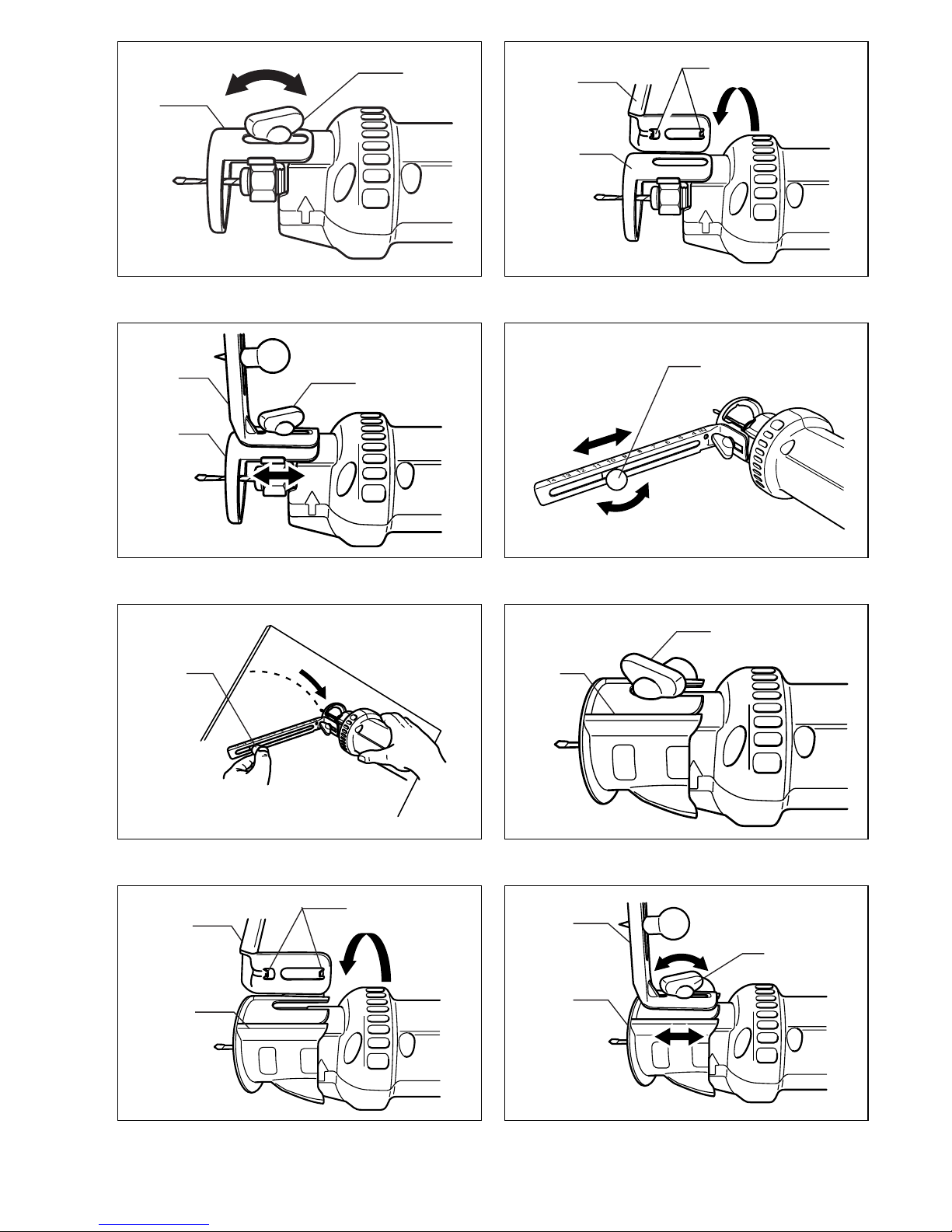
Installeren of verwijderen van de frees (Fig.1)
LET OP:
• Zorg altijd dat het gereedschap is uitgeschakeld en zijn
stekker uit het stopcontact is verwijderd alvorens de
frees te installeren of te verwijderen.
• Draai de spanmoer niet vast zonder een frees erin te
steken. Als u dit doet, zal de spankegel breken.
Om de frees te installeren, steekt u deze zo ver mogelijk
in de spankegel. Druk de asblokkering in om de as op
zijn plaats te houden en gebruik de sleutel om de span-
moer stevig vast te draaien.
OPMERKING:
Bij gebruik van de frees met een schachtdiameter van
6,35 mm, moet u eerst de adapter van de spankegel ver-
wijderen en daarna de frees installeren.
Om de frees te verwijderen, voert u de procedure voor
het installeren in de omgekeerde volgorde uit.
Vervangen van de spankegel (Fig.2)
LET OP:
• Zorg altijd dat het gereedschap is uitgeschakeld en zijn
stekker uit het stopcontact is verwijderd alvorens een
andere spankegel te installeren.
• Gebruik een spankegel en adapter van de juiste maat
voor de frees die u wilt gebruiken.
• Draai de spanmoer niet vast zonder een frees erin te
steken. Als u dit doet, zal de spankegel breken.
Om een andere spankegel te installeren, draait u de
spanmoer los en verwijdert u deze. Verwijder de geïnstal-
leerde spankegel en adapter en vervang deze door de
geschikte spankegel en adapter. Breng de spanmoer
weer aan.
Instellen van de snijdiepte (Fig.3)
LET OP:
Zorg altijd dat het gereedschap is uitgeschakeld en zijn
stekker uit het stopcontact is verwijderd alvorens de snij-
diepte in te stellen.
Om de schoen af te stellen, draait u eerst de vleugel-
schroef los. Schuif daarna de schoen naar de gewenste
positie en draai de vleugelschroef weer goed vast. Con-
troleer of er voldoende vrije ruimte is onder het werkstuk
voordat u begint te frezen, zodat de frees niet op een
hard oppervlak zoals een vloer, een werkbank e.d. zal
stoten.
Werking van de aan/uit schakelaar (Fig.4)
LET OP:
Alvorens u het gereedschap op een stopcontact aansluit,
moet u altijd controleren of de aan/uit schakelaar naar
behoren functioneert en soepel naar de “OFF” stand
terugkeert.
Druk de aan/uit schakelaar naar de “ON” stand om het
gereedschap te starten. Druk hem naar de “OFF” stand
om het gereedschap te stoppen. U kunt dit doen zowel
met de voorste schakelaar als met de stootschakelaar op
het achterste gedeelte.
BEDIENING
LET OP:
• Forceer de frees niet door deze met geweld te buigen
of te draaien. De frees kan klem komen te zitten.
• Controleer of de frees en de spanmoer goed vastzitten
voordat u het gereedschap inschakelt.
Houd het gereedschap goed vast, met de frees veilig
gericht en geen enkel oppervlak rakend, en schuif de
schakelaar naar de “ON” stand. Wacht totdat de frees op
volle toeren draait.
Wanneer u met de universele frees in het materiaal
begint te snijden, moet u het gereedschap bij een hoek
van ongeveer 45 graden houden zodat de rand van de
schoenbasis het materiaal raakt. (Fig.5)
Breng daarna het gereedschap langzaam recht omhoog
zodat de schoenbasis volledig in contact komt met het
materiaal. (Fig. 6)
Wanneer u met de stapelmuurfrees in een stapelmuur
begint te frezen, moet u de frees voorzichtig recht erin
steken totdat de schoenbasis volledig in contact komt
met het materiaal. (Fig.7)
Beweeg het gereedschap langzaam, en met een gelijk-
matige druk, met de klok mee om de snede te maken.
Om in rechte lijn te snijden, moet u een rechte plank op
het materiaal vastklemmen en deze als een geleider
gebruiken. Beweeg het gereedschap in de richting van
het pijltje en houd de schoenbasis vlak met de zijkant
van de geleideplank. (Fig.8)
Schakel het gereedschap uit nadat de snede is voltooid
en wacht totdat de frees tot stilstand is gekomen. Verwij-
der daarna voorzichtig de frees van het werkstuk.
OPMERKINGEN:
1. Tijdens het gebruik zal het gereedschap trekken ten
gevolge van de rotatie. Hoe minder druk u uitoefent,
hoe kleiner deze trekkracht zal zijn en hoe nauwkeu-
riger de snede zal zijn. Door overmatige druk of snel
frezen kan de frees vroegtijdig afstompen of breken.
2. Wanneer u freest in stapelmuur rondom stopcontac-
ten, frees dan tegen de wijzers van de klok in om
gemakkelijker te kunnen bewegen.
3. De bijgeleverde standaardfrees is uitsluitend
bestemd voor het frezen in stapelmuur. Gebruik de
standaard stapelmuurfrees niet voor het frezen in
ander materiaal dan stapelmuur.
Cirkelgeleider
Cirkeldiameters: 10 cm – 34 cm
Installeren van de cirkelgeleider
Draai de vleugelschroef waarmee de schoen is vastgezet
los. (Fig. 9)
Breng de uitsteeksels op de cirkelgeleider in één lijn met
de groeven in de schoen, en zet de schoen en de cirkel-
geleider vast met de vleugelschroef. (Fig. 10)
Om de snijdiepte af te stellen, draait u eerst de vleugel-
schroef los en daarna schuift u de schoen en de cirkelge-
leider samen naar de gewenste positie. (Fig. 11)
Draai de vleugelschroef na het afstellen weer goed vast.

19
Bediening
Draai de knop los en stel zijn positie af in overeenstem-
ming met de grootte van de te snijden cirkel. (De afmetin-
gen van het te snijden gat zijn als een algemene leidraad
aangegeven op de zijkant van de cirkelgeleider.)
(Fig. 12)
Draai de knop goed vast nadat de afstelling is voltooid.
Zet het uiteinde van de knop in het centrum van de te
snijden cirkel en begin te snijden met de klok mee.
(Fig. 13)
Stofzuigdeksel
U kunt schoner werken door een Makita stofzuiger of
stofverzamelaar op het snijgereedschap aan te sluiten.
Installeren van het stofzuigdeksel (Fig. 14)
Draai de vleugelschroef los en verwijder de schoen.
Bevestig het stofzuigdeksel en zet het goed vast met de
vleugelschroef.
Installeren van het stofzuigdeksel samen met de
cirkelgeleider
Draai de vleugelschroef waarmee het stofzuigdeksel is
vastgezet los. Breng de uitsteeksels op de cirkelgeleider
in één lijn met de groeven in het stofzuigdeksel, en zet
het stofzuigdeksel en de cirkelgeleider vast met de vleu-
gelschroef. (Fig. 15)
Om de snijdiepte af te stellen, draait u eerst de vleugel-
schroef los en daarna schuift u het stofzuigdeksel en de
cirkelgeleider samen naar de gewenste positie.
Draai de vleugelschroef na het afstellen weer goed vast.
(Fig. 16)
Aansluiten op een Makita stofzuiger of
stofverzamelaar
Sluit de slang van een stofzuiger/stofverzamelaar aan op
het stofzuigmondstuk. Wanneer u aansluit op een Makita
stofzuiger, is een optionele slang met een binnendiame-
ter van 28 mm nodig. (Fig. 17)
Wanneer u aansluit op een Makita stofverzamelaar, sluit
u de slang van de stofverzamelaar direct aan op het stof-
zuigmondstuk. (Fig. 18)
ONDERHOUD
LET OP:
Zorg er altijd voor dat de machine is uitgeschakeld en de
stekker uit het stopcontact is verwijderd alvorens onder-
houd aan de machine uit te voeren.
Opdat het gereedschap veilig en betrouwbaar blijft, die-
nen alle reparaties, onderhoud of afstellingen te worden
uitgevoerd bij een erkend Makita service centrum.
ACCESSOIRES
LET OP:
• Deze accessoires of hulpstukken worden aanbevolen
voor gebruik met het Makita gereedschap dat in deze
gebruiksaanwijzing wordt beschreven. Het gebruik van
andere accessoires of hulpstukken kan gevaar voor
persoonlijke verwonding opleveren. Gebruik de acces-
soires of hulpstukken uitsluitend voor het gespecifi-
ceerde doel.
Wenst u meer informatie over deze accessoires, neem
dan contact op met het dichtstbijzijnde Makita service-
centrum.
• Spankegel 6,35 mm/6 mm
• Adapter 3,18 – 6,35 mm/3 – 6 mm
• Stapelmuurfrees 1/8”, 1/4”, 3 mm, 6 mm
• Sleutel 17

41
ENH101-4
EC-DECLARATION OF CONFORMITY
We declare under our sole responsibility that this product
is in compliance with the following standards of standard-
ized documents,
EN60745, EN55014, EN61000
in accordance with Council Directives, 73/23/EEC,
89/336/EEC and 98/37/EC.
DÉCLARATION DE CONFORMITÉ CE
Nous déclarons sous notre entière responsabilité que ce
produit est conforme aux normes des documents stan-
dardisés suivants,
EN60745, EN55014, EN61000
conformément aux Directives du Conseil, 73/23/CEE,
89/336/CEE et 98/37/EG.
CE-KONFORMITÄTSERKLÄRUNG
Hiermit erklärt wir unter unserer alleinigen Verantwor-
tung, daß dieses Produkt gemäß den Ratsdirektiven
73/23/EWG, 89/336/EWG und 98/37/EG mit den fol-
genden Normen von Normendokumenten übereinstim-
men: EN60745, EN55014, EN61000.
DICHIARAZIONE DI CONFORMITÀ
CON LE NORME DELLA COMUNITÀ EUROPEA
Dichiariamo sotto la nostra sola responsabilità che
questo prodotto è conforme agli standard di documenti
standardizzati seguenti:
EN60745, EN55014, EN61000
secondo le direttive del Consiglio 73/23/CEE, 89/336/CEE e
98/37/CE.
EG-VERKLARING VAN CONFORMITEIT
Wij verklaren hierbij uitsluitend op eigen verant-
woordelijkheid dat dit produkt voldoet aan de volgende
normen van genormaliseerde documenten,
EN60745, EN55014, EN61000
in overeenstemming met de richtlijnen van de Raad
73/23/EEC, 89/336/EEC en 98/37/EC.
DECLARACIÓN DE CONFORMIDAD DE LA CE
Declaramos bajo nuestra sola responsabilidad que este
producto cumple con las siguientes normas de docu-
mentos normalizados,
EN60745, EN55014, EN61000
de acuerdo con las directivas comunitarias, 73/23/EEC,
89/336/EEC y 98/37/CE.
Yasuhiko Kanzaki
CE 2005
Director Amministratore
Directeur Directeur
Direktor Director
MAKITA INTERNATIONAL EUROPE LTD.
Michigan Drive, Tongwell, Milton Keynes,
Bucks MK15 8JD, ENGLAND
Responsible manufacturer: Produttore responsabile:
Fabricant responsable :Verantwoordelijke fabrikant:
Verantwortlicher Hersteller: Fabricante responsable:
Makita Corporation Anjo Aichi Japan
ENGLISH
FRANÇAISE
DEUTSCH
ITALIANO
NEDERLANDS
ESPAÑOL

42
ENH101-4
DECLARAÇÃO DE CONFORMIDADE DA CE
Declaramos sob inteira responsabilidade que este
produto obedece às seguintes normas de documentos
normalizados,
EN60745, EN55014, EN61000
de acordo com as directivas 73/23/CEE, 89/336/CEE e
98/37/CE do Conselho.
EU-DEKLARATION OM KONFORMITET
Vi erklærer hermed på eget ansvar, at dette produkt er i
overensstemmelse med de følgende standarder i de norm-
sættende dokumenter,
EN60745, EN55014, EN61000
i overensstemmelse med Rådets Direktiver 73/23/EEC,
89/336/EEC og 98/37/EC.
EG-DEKLARATION OM ÖVERENSSTÄMMELSE
Under eget ansvar deklarerar vi härmed att denna
produkt överensstämmer med följande standardiseringar
för standardiserade dokument,
EN60745, EN55014, EN61000
i enlighet med EG-direktiven 73/23/EEC, 89/336/EEC
och 98/37/EC.
EUs SAMSVARS-ERKLÆRING
Vi
erklærer
på
eget ansvar at dette produktet er i over-
ensstemmelse med følgende standard i de standardis-
erte dokumenter:
EN60745, EN55014, EN61000,
i samsvar med Råds-direktivene, 73/23/EEC,
89/336/EEC og 98/37/EC.
VAKUUTUS EC-VASTAAVUUDESTA
Yksinomaisesti vastuullisina ilmoitamme, että tämä tuote
on seuraavien standardoitujen dokumenttien standar-
dien mukainen,
EN60745, EN55014, EN61000
neuvoston direktiivien 73/23/EEC, 89/336/EEC ja
98/37/EC mukaisesti.
∆ΗΛΩΣΗ ΣΥΜΜΟΡΦΩΣΗΣ ΕΚ
∆ηλώνουµε υπ την µοναδική µας ευθύνη τι αυτ
το προιν βρίσκεται σε Συµφωνία µε τα ακλουθα
πρτυπα τυποποιηµένων εγγράφων,
EN60745, EN55014, EN61000
σύµφωνα µε τις Οδηγίες του Συµβουλίου,
73/23/EEC, 89/336/EEC και 98/37/ΚE.
Yasuhiko Kanzaki
CE 2005
Director Direktor
Direktør Johtaja
Direktör ∆ιευθυντής
MAKITA INTERNATIONAL EUROPE LTD.
Michigan Drive, Tongwell, Milton Keynes,
Bucks MK15 8JD, ENGLAND
Fabricante responsável: Ansvarlig produsent:
Ansvarlig fabrikant: Vastaava valmistaja:
Ansvarig tillverkare: Υπεύθυνος κατασκευαστής:
Makita Corporation Anjo Aichi Japan
PORTUGUÊS
DANSK
SVENSKA
NORSK
SUOMI
ΕΛΛΗΝΙΚΑ

43
ENG003-2
For European countries only
Noise and Vibration
The typical A-weighted sound pressure level is 84 dB (A).
Uncertainty is 3 dB (A).
The noise level under working may exceed 85 dB (A).
– Wear ear protection. –
The typical weighted root mean square acceleration
value is not more than 2.5 m/s2.
These values have been obtained according to
EN60745.
Pour les pays d’Europe uniquement
Bruit et vibrations
Le niveau de pression sonore pondere type A est de
84 dB (A).
L’incertitude de mesure est de 3 dB (A).
Le niveau de bruit en fonctionnement peut dépasser
85 dB (A).– Porter des protecteurs anti-bruit. –
L’accélération pondérée ne dépasse pas 2,5 m/s2.
Ces valeurs ont été obtenues selon EN60745.
Nur für europäische Länder
Geräusch- und Vibrationsentwicklung
Der typische A-bewertete Schalldruckpegel beträgt
84 dB (A).
Die Abweichung beträgt 3 dB (A).
Der Lärmpegel kann während des Betriebs 85 dB (A)
überschreiten. – Gehörschutz tragen. –
Der gewichtete Effektivwert der Beschleunigung beträgt
nicht mehr als 2,5 m/s2.
Diese Werte wurden gemäß EN60745 erhalten.
Modello per l’Europa soltanto
Rumore e vibrazione
Il livello di pressione sonora pesata secondo la curva A è
di 84 dB (A).
L’incertezza è di 3 dB (A).
Il livello di rumore durante il lavoro potrebbe superare gli
85 dB (A). – Indossare i paraorecchi. –
Il valore quadratico medio di accellerazione non supera i
2,5 m/s2.
Questi valori sono stati ottenuti in conformità EN60745.
Alleen voor Europese landen
Geluidsniveau en trilling
Het typische A-gewogen geluidsdrukniveau is 84 dB (A).
Onzekerheid is 3 dB (A).
Tijdens het werken kan het geluidsniveau 85 dB (A) over-
schrijden. – Draag oorbeschermers. –
De typische gewogen effectieve versnellingswaarde is
niet meer dan 2,5 m/s2.
Deze waarden werden verkregen in overeenstemming
met EN60745.
Para países europeos solamente
Ruido y vibración
El nivel de presión sonora ponderada A es de 84 dB (A).
Incerteza 3 dB (A).
El nivel de ruido en condiciones de trabajo puede que
sobrepase los 85 dB (A).
– Póngase protectores en los oídos. –
El valor ponderado de la aceleración no sobrepasa los
2,5 m/s2.
Estos valores han sido obtenidos de acuerdo con
EN60745.
ENGLISH
FRANÇAISE
DEUTSCH
ITALIANO
NEDERLANDS
ESPAÑOL

Makita Corporation
Anjo, Aichi, Japan
884373B994
ENG003-2
Só para países Europeus
Ruído e vibração
O nível normal de pressão sonora A é 84 dB (A).
A incerteza é de 3 db (A).
O nível de ruído durante o trabalho pode exceder
85 dB (A).
– Utilize protectores para os ouvidos –
O valor médio da aceleração é inferior a 2,5m/s2.
Estes valores foram obtidos de acordo com EN60745.
Kun for lande i Europa
Lyd og vibration
Det typiske A-vægtede lydtryksniveau er 84 dB (A).
Der er en usikkerhed på 3 dB (A).
Støjniveauet under arbejde kan overstige 85 dB (A).
– Bær høreværn. –
Den vægtede effektive accelerationsværdi overstiger ikke
2,5m/s2.
Disse værdier er beregnet i overensstemmelse med
EN60745.
Endast för Europa
Buller och vibration
Den typiska-A-vägda ljudtrycksnivån är 84 dB (A).
Osäkerheten är 3 dB (A).
Bullernivån under pågående arbete kan överstiga
85 dB (A). – Använd hörselskydd –
Det typiskt vägda effektivvärdet för acceleration översti-
ger inte 2,5m/s2.
Dessa värden har erhållits i enlighet med EN60745.
Gjelder bare land i Europa
Støy og vibrasjon
Det vanlige A-verktet lydtrykksnivå er 84 dB (A).
Usikkerheten er på 3 dB (A).
Under bruk kan støynivået overskride 85 dB (A).
– Benytt hørselvern. –
Den typiske vektede effektive akselerasjonsverdi over-
skrider ikke 2,5m/s2.
Disse verdiene er beregnet eller målt i samsvar med
EN60745.
Vain Euroopan maat
Melutaso ja tärinä
Tyypillinen A-painotettu äänenpainetaso on 84 dB (A).
Epävarmuus on 3 dB (A).
Melutaso työpaikalla saattaa ylittää 85 dB (A).
– Käytä kuulosuojaimia. –
Tyypillinen kiihtyvyyden painotettu tehollisarvo ei ylitä
2,5m/s2.
Nämä arvot on mitattu normin EN60745 mukaisesti.
Μ*νο για χώρες της Ευρώπης
Θ*ρυβος και κραδασµ*ς
Η τυπική Α-µετρούµενη ηχητική πίεση είναι
84 dB (A).
Η Αβεβαιτητα είναι 3 dB (A).
Η ένταση ήχου υπο συνθήκες εργασίας µπορεί να
µπερβεί τα 85 dB (A).
– Φοράτε ωτοασπίδες. –
Η τυπική αξία της µετρούµενης ρίζας του µέσου
τετραγώνου της επιτάχυνσης δεν ξεπερνά τα
2,5 m/s2.
Αυτές οι τιµές έχουν σηµειωθεί σύµφωνα µε το
ΕΝ60745.
PORTUGUÊS
DANSK
SVENSKA
NORSK
SUOMI
ΕΛΛΗΝΙΚΑ
Other manuals for 3706
2
Table of contents
Other Makita Power Tools manuals

Makita
Makita HM1140C User manual

Makita
Makita HM0810T User manual

Makita
Makita DTW280 User manual

Makita
Makita HM0870C User manual

Makita
Makita BJS160 User manual

Makita
Makita AN901 User manual

Makita
Makita SG1250 User manual

Makita
Makita xmt03 User manual

Makita
Makita DMP180Z User manual

Makita
Makita 4604D User manual

Makita
Makita 6922NB Quick start guide

Makita
Makita LXRH02 User manual

Makita
Makita HR008G User manual

Makita
Makita 2012NB User manual

Makita
Makita SG1250 User manual

Makita
Makita HR3540C User manual

Makita
Makita AT450H User manual

Makita
Makita JS1602 User manual

Makita
Makita DJV182 User manual

Makita
Makita CG100D User manual