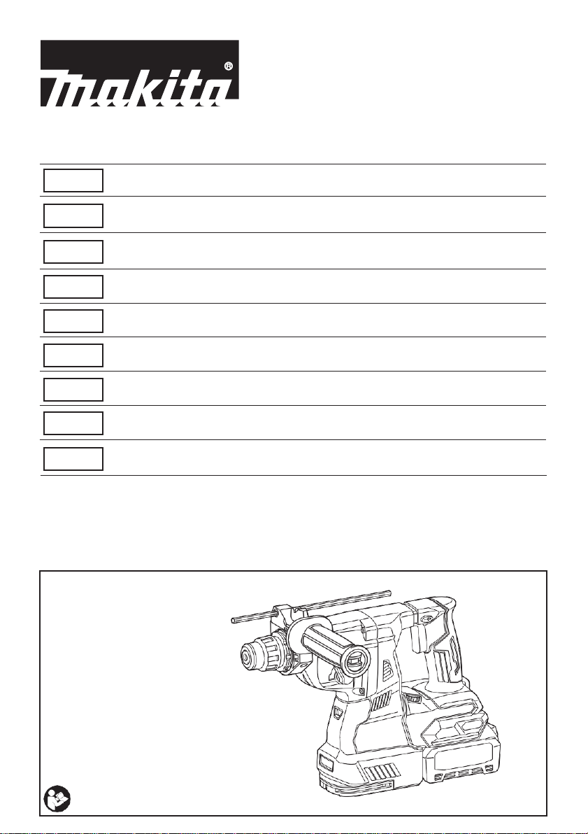
Makita HR004G User manual

Cordless Combination Hammer
INSTRUCTION MANUAL 11
Batteridriven
kombinationshammare
Batteridrevet
kombinasjonshammer
BRUKSANVISNING 26
BRUKSANVISNING 40
Akkukäyttöinenyhdistelmäpora
KÄYTTÖOHJE 54
Akku-kombinationshammer BRUGSANVISNING 68
Bezvadu kombinētais veseris LIETOŠANAS INSTRUKCIJA 83
Belaidis kombinacinis gręžtuvas
NAUDOJIMO INSTRUKCIJA 98
Juhtmeta kombinatsioonihaamer
KASUTUSJUHEND 113
Аккумуляторный
трехрежимный перфоратор РУКОВОДСТВО ПО
ЭКСПЛУАТАЦИИ 128
RU
ET
LT
LV
DA
FI
NO
SV
EN
HR001G
HR002G
HR003G
HR004G

2
1
Fig.5
1
2
3
Fig.1
1
2
Fig.2
1
A B
Fig.6
1
Fig.3
1 2
3
Fig.7
1
Fig.4
1 2
3 4
Fig.8

3
1
2
Fig.9
Fig.13
1
Fig.10
1
2
3
Fig.14
1
Fig.11
1 2
Fig.15
1
Fig.12

4
2
1
Fig.20
1
Fig.16
A
Fig.17
1
1
Fig.21
1
Fig.18
1
2
Fig.22
1
Fig.19
1
Fig.23

5
1
2
Fig.30
1
Fig.26
3
4
1 2
Fig.24
1
Fig.27
1
2
Fig.28
Fig.25
1
Fig.29

6
1 2
Fig.35
Fig.31
1
Fig.38
Fig.34
Fig.32
1
2
Fig.36
Fig.33
1
2
Fig.37

7
Fig.42
Fig.43
1
Fig.39
Fig.40
1
Fig.44
Fig.41
2
3
4 1
Fig.45

8
1 2
1 2
Fig.48
1
2
3
Fig.46
1
Fig.47
Fig.49
1
Fig.50

9
1 2
Fig.51
1 2
1 2
Fig.54
1
Fig.52
1
Fig.55
1
Fig.53
2
1
Fig.56

10
1
2
Fig.57
1
2
Fig.58

11 ENGLISH
ENGLISH (Original instructions)
SPECIFICATIONS
Model:
HR001G
HR002G
HR003G
HR004G
Capacities
Concrete
28 mm
Core bit
54 mm
Diamond core bit (dry type)
65 mm
Steel
13 mm
Wood
32 mm
No load speed
0 - 980 min-1
Blows per minute
0 - 5,000 min-1
Rated voltage
D.C. 36 V - 40 V max
Overall length
with BL4025
358 mm
389 mm
358 mm
389 mm
with BL4040
373 mm
404 mm
373 mm
404 mm
Net weight
3.9 - 4.6 kg
4.1 - 4.6 kg
3.9 - 4.6 kg
4.0 - 4.5 kg
Optional accessory
Model:
DX12 (For HR001G/HR003G)
DX14 (For HR002G/HR004G)
Suction performance
350 l/min
Operating stroke
Up to 190mm
Suitable drill bit
Up to 260mm
Rated voltage
D.C. 36 V - 40 V max
Net weight
1.6 kg
•
Due to our continuing program of research and development, the specifications herein are subject to change without notice.
•Specifications maydiffer from countrytocountry.
•The weight may differ depending on the attachment(s), including the battery cartridge. The lightest and heavi-
est combination, according to EPTA-Procedure 01/2014, are shown in the table.
Applicable battery cartridge and charger
Battery cartridge
BL4025 / BL4040
Charger
DC40RA
•
Some of the battery cartridges and chargers listed above may not be available depending on your region of residence.
Intended use
The tool is intended for hammer drilling and drilling in
brick, concrete and stone as well as for chiselling work.
It is also suitable for drilling without impact in wood,
metal, ceramic and plastic.
Noise
The typical A-weighted noise level determined accord-
ing to EN60745-2-6:
Model HR001G
Sound pressure level (LpA) : 95 dB(A)
Sound power level (LWA) : 106 dB (A)
Uncertainty (K) : 3 dB(A)
Model HR002G
Sound pressure level (LpA) : 93 dB(A)
Sound power level (LWA) : 104 dB (A)
Uncertainty (K) : 3 dB(A)
Model HR003G
Sound pressure level (LpA) : 95 dB(A)
Sound power level (LWA) : 106 dB (A)
Uncertainty (K) : 3 dB(A)
Model HR004G
Sound pressure level (LpA) : 93 dB(A)
Sound power level (LWA) : 104 dB (A)
Uncertainty (K) : 3 dB(A)
Model HR001G with DX12
Sound pressure level (LpA) : 93 dB(A)
Sound power level (LWA) : 104 dB (A)
Uncertainty (K) : 3 dB(A)
Model HR002G with DX14
Sound pressure level (LpA) : 93 dB(A)
Sound power level (LWA) : 104 dB (A)
Uncertainty (K) : 3 dB(A)
WARNING: Only use the battery cartridges and chargers listed above. Use of any other battery cartridges
and chargers may cause injury and/or fire.

12 ENGLISH
Model HR003G with DX12
Sound pressure level (LpA) : 93 dB(A)
Sound power level (LWA) : 104 dB (A)
Uncertainty (K) : 3 dB(A)
Model HR004G with DX14
Sound pressure level (LpA) : 93 dB(A)
Model HR003G
Sound power level (LWA) : 104 dB (A)
Uncertainty (K) : 3 dB(A)
Vibration
The following table shows the vibration total value
(tri-axial vector sum) determined according to applica-
ble standard.
Model HR001G
Work mode
Vibration
emission
Uncertainty (K)
Applicable
standard
Hammer drill-
ing into con-
crete (a
h, HD
)
7.0 m/s2
1.5 m/s2
EN60745-2-6
Hammer
drilling into
concretewith
DX12 (ah, HD)
7.0 m/s2
1.5 m/s2
EN60745-2-6
Chiselling func-
tion with side
grip (a
h, Cheq
)
6.5 m/s2
1.5 m/s2
EN60745-2-6
Drilling into
metal (ah,D)
2.5 m/s2or
less
1.5 m/s2
EN60745-2-1
Model HR002G
Model HR004G
Work mode
Vibration
emission
Uncertainty (K)
Applicable
standard
Hammer drill-
ing into con-
crete (a
h, HD
)
6.5 m/s2
1.5 m/s2
EN60745-2-6
Hammer
drilling into
concretewith
DX14 (ah, HD)
6.0 m/s2
1.5 m/s2
EN60745-2-6
Chiselling func-
tion with side
grip (a
h, Cheq
)
7.5 m/s2
1.5 m/s2
EN60745-2-6
Drilling into
metal (ah,D)
2.5 m/s2
1.5 m/s2
EN60745-2-1
EC Declaration of Conformity
For European countries only
The EC declaration of conformity is included as Annex A
to this instruction manual.
WARNING: The vibration emission during
actual use of the power tool can differ from the
declared value(s) depending on the ways in which
the tool is used especially what kind of workpiece
is processed.
WARNING: Be sure to identify safety mea-
sures to protect the operator that are based on an
estimation of exposure in the actual conditions of
use (taking account of all parts of the operating
cycle such as the times when the tool is switched
off and when it is running idle in addition to the
trigger time).
NOTE: The declared vibration total value(s) has been
measured in accordance with a standard test method
and maybe used for comparing one tool with another.
NOTE: The declared vibration total value(s) may also
be used in a preliminary assessment of exposure.
WARNING: Wear ear protection.
WARNING:
The noise emission during actual
use of the power tool can differ from the declared val-
ue(s) depending on the ways in which the tool is used
especially what kind of workpiece is processed.
WARNING:
Be sure to identify safety measures
to protect the operator that are based on an estima-
tion of exposure in the actual conditions of use (tak-
ing account of all parts of the operating cycle such
as the times when the tool is switched off and when
it is running idle in addition to the trigger time).
NOTE:
The declared noise emission value(s) has been
measured in accordance with a standard test method
and may be used for comparing one tool with another.
NOTE: The declared noise emission value(s) may
also be used in a preliminary assessment of exposure.
Work mode
Vibration
emission
Uncertainty (K)
Applicable
standard
Hammer drill-
ing into con-
crete (a
h, HD
)
7.0 m/s2
1.5 m/s2
EN60745-2-6
Hammer
drilling into
concretewith
DX12 (ah, HD)
7.0 m/s2
1.5 m/s2
EN60745-2-6
Chiselling func-
tion with side
grip (a
h, Cheq
)
7.0 m/s2
1.5 m/s2
EN60745-2-6
Drilling into
metal (ah,D)
2.5 m/s2or
less
1.5 m/s2
EN60745-2-1
Work mode
Vibration
emission
Uncertainty (K)
Applicable
standard
Hammer drill-
ing into con-
crete (a
h, HD
)
6.5 m/s2
1.5 m/s2
EN60745-2-6
Hammer
drilling into
concretewith
DX14 (ah, HD)
6.0 m/s2
1.5 m/s2
EN60745-2-6
Chiselling func-
tion with side
grip (a
h, Cheq
)
7.5 m/s2
1.5 m/s2
EN60745-2-6
Drilling into
metal (ah,D)
2.5 m/s2
1.5 m/s2
EN60745-2-1

13 ENGLISH
SAFETY WARNINGS
General power tool safety warnings
Save all warnings and instruc-
tions for future reference.
The term "power tool" in the warnings refers to your
mains-operated (corded) power tool or battery-operated
(cordless) power tool.
15. Always be sure that the tool is switched
off and the battery cartridge and the bit are
removed before handing the tool to other
person.
16. Before operation, make sure that there is no
buried object such as electric pipe, water pipe
or gas pipe in the working area. Otherwise, the
drill bit/chisel may touch them, resulting an electric
shock, electrical leakage or gas leak.
SAVE THESE INSTRUCTIONS.
1. Wear ear protectors. Exposure to noise can
cause hearing loss.
2. Use auxiliary handle(s), if supplied with the
tool. Loss of control can cause personal injury.
3. Hold power tool by insulated gripping sur-
faces, when performing an operation where the
cutting accessory may contact hidden wiring.
Cutting accessory contacting a "live" wire may
make exposed metal parts of the power tool "live"
and could give the operator an electric shock.
4. Wear a hard hat (safety helmet), safety glasses
and/or face shield. Ordinary eye or sun glasses
are NOT safety glasses. It is also highly recom-
mended that you wear a dust mask and thickly
padded gloves.
5. Be sure the bit is secured in place before
operation.
6.
Under normal operation, the tool is designed to
produce vibration. The screws can come loose
easily, causing a breakdown or accident. Check
tightness of screws carefully before operation.
7. In cold weather or when the tool has not been
used for a long time, let the tool warm up for
a while by operating it under no load. This
will loosen up the lubrication. Without proper
warm-up, hammering operation is difficult.
8. Always be sure you have a firm footing. Be
sure no one is below when using the tool in
high locations.
9. Hold the tool firmly with both hands.
10. Keep hands away from moving parts.
11. Do not leave the tool running. Operate the tool
only when hand-held.
12. Do not point the tool at any one in the area
when operating. The bit could fly out and
injure someone seriously.
13. Do not touch the bit, parts close to the bit, or
workpiece immediately after
operation;
they
may be extremely hot and could burn your skin.
14. Some material contains chemicals which may
be toxic. Take caution to prevent dust inhala-
tion and skin contact. Follow material supplier
safety data.
1. Before using battery cartridge, read all instruc-
tions and cautionary markings on (1) battery
charger, (2) battery, and (3) product using
battery.
2. Do not disassemble or tamper the battery
cartridge. It may result in a fire, excessive heat,
or explosion.
3. If operating time has become excessively
shorter, stop operating immediately. It may
result in a risk of overheating, possible burns
and even an explosion.
4. If electrolyte gets into your eyes, rinse them
out with clear water and seek medical atten-
tion right away. It may result in loss of your
eyesight.
5. Do not short the battery cartridge:
(1) Do not touch the terminals with any con-
ductive material.
(2) Avoid storing battery cartridge in a con-
tainer with other metal objects such as
nails, coins, etc.
(3) Do not expose battery cartridge to water
or rain.
A battery short can cause a large current
flow, overheating, possible burns and even a
breakdown.
6. Do not store the tool and battery cartridge in
locations where the temperature may reach or
exceed 50 °C (122 °F).
7. Do not incinerate the battery cartridge even if
it is severely damaged or is completely worn
out. The battery cartridge can explode in a fire.
8. Do not nail, cut, crush, throw, drop the battery
cartridge, or hit against a hard object to the
battery cartridge. Such conduct may result in a
fire, excessive heat, or explosion.
9. Do not use a damaged battery.
10. The contained lithium-ion batteries are subject
to the Dangerous Goods Legislation require-
ments.
For commercial transports e.g. by third parties,
forwarding agents, special requirement on pack-
aging and labeling must be observed.
Important safety instructions for
battery cartridge
CORDLESS ROTARY HAMMER
SAFETY WARNINGS
WARNING: DO NOT let comfort or familiarity
with product (gained from repeated use) replace
strict adherence to safety rules for the subject
product. MISUSE or failure to follow the safety
rules stated in this instruction manual may cause
serious personal injury.
WARNING: Read all safety warnings, instruc-
tions, illustrations and specifications provided
with this power tool. Failure to follow all instructions
listed below may result in electric shock, fire and/or
serious injury.

14 ENGLISH
For preparation of the item being shipped, consult-
ing an expert for hazardous material is required.
Please also observe possibly more detailed
national regulations.
Tape or mask off open contacts and pack up the
battery in such a manner that it cannot move
around in the packaging.
11. When disposing the battery cartridge, remove
it from the tool and dispose of it in a safe
place. Follow your local regulations relating to
disposal of battery.
12. Use the batteries only with the products
specified by Makita. Installing the batteries to
non-compliant products may result in a fire, exces-
sive heat, explosion, or leak of electrolyte.
13. If the tool is not used for a long period of time,
the battery must be removed from the tool.
14. During and after use, the battery cartridge may
take on heat which can cause burns or low
temperature burns. Pay attention to the han-
dling of hot battery cartridges.
15. Do not touch the terminal of the tool imme-
diately after use as it may get hot enough to
cause burns.
16. Do not allow chips, dust, or soil stuck into the
terminals, holes, and grooves of the battery
cartridge. It may result in poor performance or
breakdown of the tool or battery cartridge.
17. Unless the tool supports the use near a
high-voltage electrical power lines, do not use
the battery cartridge near a high-voltage elec-
trical power lines. It may result in a malfunction
or breakdown of the tool or battery cartridge.
SAVE THESE INSTRUCTIONS.
Tips for maintaining maximum
battery life
1. Charge the battery cartridge before completely
discharged. Always stop tool operation and
charge the battery cartridge when you notice
less tool power.
2. Never recharge a fully charged battery car-
tridge. Overcharging shortens the battery
service life.
3. Charge the battery cartridge with room tem-
perature at 10 °C - 40 °C (50 °F - 104 °F). Let
a hot battery cartridge cool down before
charging it.
4. When not using the battery cartridge, remove
it from the tool or the charger.
5. Charge the battery cartridge if you do not use
it for a long period (more than six months).
1. Do not disassemble or tamper with the wire-
less unit.
2. Keep the wireless unit away from young chil-
dren. If accidentally swallowed, seek medical
attention immediately.
3. Use the wireless unit only with Makita tools.
4. Do not expose the wireless unit to rain or wet
conditions.
5. Do not use the wireless unit in places where
the temperature exceeds 50°C (122°F).
6. Do not operate the wireless unit in places
where medical instruments, such as heart
pace makers are nearby.
7. Do not operate the wireless unit in places
where automated devices are nearby. If oper-
ated, automated devices may develop malfunction
or error.
8. Do not operate the wireless unit in places
under high temperature or places where
static electricity or electrical noise could be
generated.
9. The wireless unit can produce electromagnetic
fields (EMF) but they are not harmful to the
user.
10. The wireless unit is an accurate instrument. Be
careful not to drop or strike the wireless unit.
11. Avoid touching the terminal of the wireless
unit with bare hands or metallic materials.
12. Always remove the battery on the product
when installing the wireless unit into it.
13. When opening the lid of the slot, avoid the
place where dust and water may come into the
slot. Always keep the inlet of the slot clean.
14. Always insert the wireless unit in the correct
direction.
15. Do not press the wireless activation button
on the wireless unit too hard and/or press the
button with an object with a sharp edge.
16. Always close the lid of the slot when
operating.
17. Do not remove the wireless unit from the slot
while the power is being supplied to the tool.
Doing so may cause a malfunction of the wireless
unit.
18. Do not remove the sticker on the wireless unit.
19. Do not put any sticker on the wireless unit.
20. Do not leave the wireless unit in a place where
static electricity or electrical noise could be
generated.
21. Do not leave the wireless unit in a place sub-
ject to high heat, such as a car sitting in the
sun.
22. Do not leave the wireless unit in a dusty or
powdery place or in a place corrosive gas
could be generated.
23. Sudden change of the temperature may bedew
the wireless unit. Do not use the wireless unit
until the dew is completely dried.
Important safety instructions for
wireless unit
CAUTION: Only use genuine Makita batteries.
Use of non-genuine Makita batteries, or batteries that
have been altered, may result in the battery bursting
causing fires, personal injury and damage. It will
also void the Makita warranty for the Makita tool and
charger.

15 ENGLISH
24. When cleaning the wireless unit, gently wipe
with a dry soft cloth. Do not use benzine, thin-
ner, conductive grease or the like.
25. When storing the wireless unit, keep it in the
supplied case or a static-free container.
26. Do not insert any devices other than Makita
wireless unit into the slot on the tool.
27. Do not use the tool with the lid of the slot dam-
aged. Water, dust, and dirt come into the slot may
cause malfunction.
28. Do not pull and/or twist the lid of the slot more
than necessary. Restore the lid if it comes off
from the tool.
29. Replace the lid of the slot if it is lost or
damaged.
SAVE THESE INSTRUCTIONS.
►
Fig.1: 1. Red indicator 2. Button 3. Battery cartridge
Toremove the battery cartridge, slide it from the tool
while sliding the button on the front of the cartridge.
To install the battery cartridge, align the tongue on the
battery cartridge with the groove in the housing and slip
it into place. Insert it all the way until it locks in place
with a little click. If you can see the red indicator on the
upper side of the button, it is not locked completely.
Press the check button on the battery cartridge to indi-
cate the remaining battery capacity. The indicator lamps
light up for a few seconds.
►
Fig.2: 1. Indicator lamps 2. Check button
Indicator lamps
Remaining
capacity
Lighted
Off
Blinking
75% to 100%
50% to 75%
25% to 50%
0% to 25%
Charge the
battery.
The battery
may have
malfunctioned.
Tool / battery protection system
The tool is equipped with a tool/battery protection sys-
tem. This system automatically cuts off power to the
motor to extend tool and battery life. The tool will auto-
matically stop during operation if the tool or battery is
placed under one of the following conditions:
Overload protection
When the battery is operated in a manner that causes
it to draw an abnormally high current, the tool automat-
ically stops without any indication. In this situation, turn
the tool off and stop the application that caused the tool
to become overloaded. Then turn the tool on to restart.
Overheat protection
When the tool or battery is overheated, the tool stops
automatically. In this case, let the tool and battery cool
before turning the tool on again.
Overdischarge protection
When the battery capacity is not enough, the tool stops
automatically. In this case, remove the battery from the
tool and charge the battery.
NOTE: When the tool is overheated, the lamp blinks.
NOTE: Depending on the conditions of use and the
ambient temperature, the indication may differ slightly
from the actual capacity.
Indicating the remaining battery
capacity
CAUTION: Always install the battery cartridge
fully until the red indicator cannot be seen. If not,
it may accidentally fall out of the tool, causing injury to
you or someone around you.
CAUTION: Do not install the battery cartridge
forcibly. If the cartridge does not slide in easily, it is
not being inserted correctly.
CAUTION: Always switch off the tool before
installing or removing of the battery cartridge.
CAUTION: Hold the tool and the battery car-
tridge firmly when installing or removing battery
cartridge. Failure to hold the tool and the battery
cartridge firmly may cause them to slip off your hands
and result in damage to the tool and battery cartridge
and a personal injury.
CAUTION: Always be sure that the tool is
switched off and the battery cartridge is removed
before adjusting or checking function on the tool.
FUNCTIONAL
DESCRIPTION
Installing orremoving battery
cartridge

16 ENGLISH
Switch action
►
Fig.3: 1. Switch trigger
To start the tool, simply pull the switch trigger. Tool
speed is increased by increasing pressure on the switch
trigger. Release the switch trigger to stop.
Speed change
The revolutions and blows per minute can be adjusted
by turning the adjusting dial. The dial is marked 1 (low-
est speed) to 5 (full speed).
►
Fig.4:
1.
Adjusting dial
Refer to the table below for the relationship between the number
on the adjusting dial and the revolutions and blows per minute.
Number
Revolutions per
minute
Blows per minute
5
980
5,000
4
870
4,440
3
630
3,210
2
380
1,940
1
300
1,530
Reversing switch action
►
Fig.6: 1. Reversing switch lever
This tool has a reversing switch to change the direction
of rotation. Depress the reversing switch lever from the
A side for clockwise rotation or from the B side for coun-
terclockwise rotation.
When the reversing switch lever is in the neutral posi-
tion, the switch trigger cannot be pulled.
For HR002G/HR004G
The quick change chuck for SDS-plus can be easily
exchanged for the quick change drill chuck.
Removing the quick change chuck
for SDS-plus
Lighting upthe front lamp
►
Fig.5: 1. Lamp
Grasp the change cover of the quick change chuck
for SDS-plus and turn in the direction of the arrow
until the change cover line moves from the symbol
to the symbol. Pull forcefully in the direction of the
arrow.
►
Fig.7: 1. Quick change chuck for SDS-plus
2. Change cover 3. Change cover line
Pull the switch trigger to light up the lamp. The lamp
keeps on lighting while the switch trigger is being pulled.
The lamp goes out approximately 10 seconds after
releasing the switch trigger.
CAUTION: Do not look in the light or see the
source of light directly.
CAUTION: Before removing the quick change
chuck for SDS-plus, be sure to remove the bit.
Changing thequick change chuck
for SDS-plus
CAUTION: Always check the direction of
rotation before operation.
CAUTION: Use the reversing switch only after
the tool comes to a complete stop. Changing the
direction of rotation before the tool stops may dam-
age the tool.
CAUTION: When not operating the tool,
always set the reversing switch lever to the neu-
tral position.
CAUTION: Do not turn the adjusting dial when
the tool is running. Failure to do so may result in
the loss of control of the tool and cause an injury.
WARNING: Before installing the battery car-
tridge into the tool, always check to see that the
switch trigger actuates properly and returns to
the "OFF" position when released.
CAUTION: For HR001G/HR002G
If the lamp goes off after blinking for a few sec-
onds, the active feedback sensing technology
is not working properly. Ask your local Makita
Service Center for repair.
NOTE: Soft no-load rotation function (For
HR001G/HR002G)
When the speed adjusting dial is set to "4" or higher,
the tool automatically reduces the speed at no-load to
reduce the vibration under no-load. Once operation
starts with a bit against concrete, blows per minute
increase and reach the numbers as shown in the
table. When temperature is low and there is less
fluidity in grease, the tool may not have this function
even with the motor rotating.
NOTICE: The speed adjusting dial can be turned
only as far as 5 and back to 1. Do not force it past
5 or 1, or the speed adjusting function may no
longer work.
NOTICE: If the tool is operated continuously at
low speed for a long time, the motor will get over-
loaded, resulting in tool malfunction.
NOTE: Use a dry cloth to wipe the dirt off the lens of
the lamp. Be careful not to scratch the lens of lamp, or
it may lower the illumination.
NOTE: If the dust collection system is installed on the
tool, the lamp of the dust collection system lights up
instead of the lamp of the tool.

17 ENGLISH
CAUTION: Always remove the battery when
hanging the tool with the hook.
CAUTION: Never hook the tool at high loca-
tion or on potentially unstable surface.
CAUTION:
Do not use damaged hook and screws.
Before use, always check for damages, cracks or defor-
mations, and make sure that the screws are tightened.
CAUTION: Make sure that the hook is
securely installed with the screws.
CAUTION: Do not remove the battery car-
tridge while hanging the tool. The tool may fall if the
screws are not tightened.
CAUTION:
Always use a locking carabiner
(multi-action and screw gate type) and be sure to
attach the lanyard (tether strap) to the double looped
portion of the hook.
Improper attachment may cause
tool drop from the hook and result in personal injury.
Installing the quick change drill
chuck
Check the line of the quick change drill chuck shows
the symbol. Grasp the change cover of the quick
change drill chuck and set the line to the symbol.
Place the quick change drill chuck on the spindle of the
tool. Grasp the change cover of the quick change drill
chuck and turn the change cover line to the symbol
until a click can clearly beheard.
►
Fig.8: 1. Quick change drill chuck 2. Spindle
3. Change cover line 4. Change cover
Selecting the action mode
Connecting lanyard (tether strap) to
the hook
Rotation with hammering
For drilling in concrete, masonry, etc., rotate the action
mode changing knob to the symbol. Use a tungsten-
carbide tipped bit (optional accessory).
►
Fig.9: 1.
Rotation with hammering
2.
Action mode
changing knob
Rotation only
For drilling in wood, metal or plastic materials, rotate
the action mode changing knob tothe symbol. Use a
twist drill bit or wood drill bit.
►
Fig.10: 1. Rotation only
Hammering only
For chipping, scaling or demolition operations, rotate
the action mode changing knob tothe symbol. Use a
bull point, cold chisel, scaling chisel, etc.
►
Fig.11: 1. Hammering only
Hook
The hook is also used for connecting the lanyard (tether
strap). Be sure to connect the lanyard (tether strap) to
the double looped portion of the hook.
►
Fig.14: 1. Double looped portion of the hook
2. Lanyard (tether strap) 3. Locking cara-
biner (multi-action and screw gate type)
Optional accessory
Push in the guide while pushing up the guide adjustment
button, and then release the button at the desired position.
►
Fig.15: 1. Guide 2. Guide adjustment button
If a long drill bit is installed, extend the guide by pushing
up the extension button.
►
Fig.16: 1. Extension button
Optional accessory
Slide the depth adjustment button to the desired posi-
tion while pushing it up. The distance (A) is the drilling
depth.
►
Fig.17: 1. Depth adjustment button
Torque limiter
The hook is convenient for temporarily hanging the tool.
To use the hook, simply lift up hook until it snaps into
the open position. When not in use, always lower hook
until it snaps into the closed position.
►
Fig.12: 1. Hook
►
Fig.13
The torque limiter will actuate when a certain torque
level is reached. The motor will disengage from the
output shaft. When this happens, the drill bit will stop
turning.
NOTE: Before adjusting the nozzle position, release
the nozzle forward completely by pushing up the
guide adjustment button.
NOTICE: As soon as the torque limiter actuates,
switch off the tool immediately. This will help pre-
vent premature wear of the tool.
NOTICE: Drill bits such as hole saw, which tend
to pinch or catch easily in the hole, are not appro-
priate for this tool. This is because they will cause
the torque limiter to actuate too frequently.
NOTICE: Do not rotate the action mode chang-
ing knob when the tool is running. The tool will be
damaged.
NOTICE: To avoid rapid wear on the mode
change mechanism, be sure that the action mode
changing knob is always positively located in one
of the three action mode positions.
Adjusting the nozzleposition of the
dust collection system
Adjusting the drilling depth of the
dust collection system

18 ENGLISH
Electronic function
The tool is equipped with the electronic functions for
easyoperation.
•Constant speed control
The speed control function provides the constant
rotation speed regardless of load conditions.
•Active Feedback sensing Technology (For
HR001G/HR002G)
If the tool is swung at the predetermined accelera-
tion during operation, the motor is forcibly stopped
to reduce the burden on the wrist.
ASSEMBLY
Side grip (auxiliary handle)
Toinstall the side grip, follow the steps below.
1. Loosen the thumb screw on the side grip.
►
Fig.18: 1. Thumb screw
2. Attach the side grip while pressing the thumb
screw so that the grooves on the grip fit in the protru-
sions on the tool barrel.
►
Fig.19: 1. Thumb screw
3. Tighten the thumb screw to secure the grip. The
grip can be fixed at desired angle.
Grease
Coat the shank end of the drill bit beforehand with a
small amount of grease (about 0.5 - 1 g).
This chuck lubrication assures smooth action and lon-
ger service life.
Installing orremoving drill bit
Clean the shank end of the drill bit and apply grease
before installing the drill bit.
►
Fig.20: 1. Shank end 2. Grease
Insert the drill bit into the tool. Turn the drill bit and push
it in until it engages.
After installing the drill bit, always make sure that the
drill bit is securely held in place bytrying to pull it out.
►
Fig.21: 1. Drill bit
Toremove the drill bit, pull the chuck cover down all the
way and pull the drill bit out.
►
Fig.22: 1. Drill bit 2. Chuck cover
The chisel can be secured at the desired angle. To
change the chisel angle, rotate the action mode chang-
ing knob to the O symbol. Turn the chisel to the desired
angle.
►
Fig.23:
1.
Action mode changing knob
Rotate the action mode changing knob to the sym-
bol. Then make sure that the chisel is securely held in
place byturning it slightly.
Depth gauge
The depth gauge is convenient for drilling holes of
uniform depth.
Press and hold the lock button, and then insert the
depth gauge into the hex hole. Make sure that the
toothed side of the depth gauge faces the marking.
►
Fig.24: 1. Depth gauge 2. Lock button 3. Marking
4. Toothedside
Adjust the depth gauge by moving it back and forth
while pressing the lock button. After the adjustment,
release the lock button to lock the depth gauge.
Optional accessory
To install the dust collection system, insert the tool into
the dust collection system all the way until it locks in
place with a little double click.
►
Fig.25
Toremove the dust collection system, pull the tool while
pressing the lock-off button.
►
Fig.26: 1. Lock-off button
Dust cup
Optional accessory
Use the dust cup to prevent dust from falling over the
tool and on yourself when performing overhead drilling
operations. Attach the dust cup to the bit as shown in
the figure. The size of bits which the dust cup can be
attached tois as follows.
Model
Bit diameter
Dust cup 5
6 mm - 14.5 mm
Dust cup 9
12 mm - 16 mm
►
Fig.27: 1. Dust cup
Installing or removing the dust
collection system
NOTE: Make sure that the depth gauge does not
touch the main body of the tool when attaching it.
CAUTION: Always be sure that the tool is
switched off and the battery cartridge is removed
before carrying out any work on the tool.
NOTE: This function does not work if the acceleration
does not reach the predetermined one when the tool
is swung.
NOTE: If the bit is swung at the predetermined
acceleration during chipping, scaling, or demolishing,
the motor is forcibly stopped. In this case, release
the switch trigger, and then pull the switch trigger to
restart the tool.
CAUTION: Always use the side grip to ensure
safe operation.
CAUTION: After installing or adjusting the
side grip, make sure that the side grip is firmly
secured.
Chisel angle(when chipping,
scaling or demolishing)

19 ENGLISH
CAUTION: Always use the side grip (auxiliary
handle) and firmly hold the tool by both side grip
and switch handle during operations.
CAUTION: Always make sure that the work-
piece is secured before operation.
CAUTION: Do not pull the tool out forcibly
even the bit gets stuck. Loss of control may
cause injury.
CAUTION: The dust collection system is
intended for drilling in concrete only. Do not use
the dust collection system for drilling in metal or
wood.
CAUTION: When using the tool with the dust
collection system, be sure to attach the filter
to the dust collection system to prevent dust
inhalation.
CAUTION: Before using the dust collection
system, check that the filter is not damaged.
Failure to do so maycause dust inhalation.
CAUTION: The dust collection system col-
lects the generated dust at a considerable rate,
but not all dust can be collected.
Dust cup set
Optional accessory
Before installing the dust cup set, remove the bit from
the tool if installed.
Install the dust cup set on the tool so that the sym-
bol on the dust cup is aligned with the groove in the tool.
►
Fig.28: 1. symbol 2. Groove
►
Fig.33
Hammer drilling operation
►
Fig.29: 1. Dust cap
Toremove the dust cup set, remove the bit while pulling
the chuck cover in the direction of the arrow.
►
Fig.30: 1. Bit 2. Chuck cover
Hold the root of dust cup and pull it out.
►
Fig.31
►
Fig.32
OPERATION
Set the action mode changing knob to the symbol.
Position the drill bit at the desired location for the hole,
then pull the switch trigger. Do not force the tool. Light
pressure gives best results. Keep the tool in position
and prevent it from slipping away from the hole.
Do not apply more pressure when the hole becomes
clogged with chips or particles. Instead, run the tool at
an idle, then remove the drill bit partially from the hole.
By repeating this several times, the hole will be cleaned
out and normal drilling may beresumed.
Chipping/Scaling/Demolition
Set the action mode changing knob to the symbol.
Hold the tool firmly with both hands. Turn the tool on
and applyslight pressure on the tool so that the tool will
not bounce around, uncontrolled.
Pressing very hard on the tool will not increase the
efficiency.
►
Fig.34
Drilling in wood or metal
NOTE: Eccentricity in the drill bit rotation may occur
while operating the tool with no load. The tool auto-
matically centers itself during operation. This does not
affect the drilling precision.
NOTE: If the cap comes off from the dust cup, attach
it with its printed side facing up so that groove on the
cap fits in the inside periphery of the attachment.
NOTE: If you connect a vacuum cleaner to the dust
cup set, remove the dust cap before connecting it.
NOTE: If the battery cartridge is in low temperature,
the tool’s capability may not be fully obtained. In this
case, warm up the battery cartridge by using the
tool with no load for a while to fully obtain the tool’s
capability.
CAUTION: There is tremendous and sudden
twisting force exerted on the tool/drill bit at the time of
hole break-through, when the hole becomes clogged
with chips and particles, or when striking reinforcing
rods embedded in the concrete. Always use the side
grip (auxiliary handle) and firmly hold the tool by
both side grip and switch handle during opera-
tions. Failure to do so may result in the loss of control
of the tool and potentially severe injury.
CAUTION: Hold the tool firmly and exert care
when the drill bit begins to break through the
workpiece. There is a tremendous force exerted on
the tool/drill bit at the time of hole break through.
CAUTION: A stuck drill bit can be removed
simply by setting the reversing switch to reverse
rotation in order to back out. However, the tool
may back out abruptly if you do not hold it firmly.
CAUTION: Always secure workpieces in a
vise or similar hold-down device.
NOTICE: Do not use the dust collection system
for core drilling or chiseling.
NOTICE: Do not use the dust collection system
for drilling in wet concrete or use this system
in wet environment. Failure to do so may cause
malfunction.

20 ENGLISH
CAUTION: Do not turn the dial on the dust
case while the dust case is removed from the
dust collection system. Doing so may cause dust
inhalation.
CAUTION: Always switch off the tool when
turning the dial on the dust case. Turning the dial
while the tool is running may result in the loss of
control of the tool.
►
Fig.37: 1. Dust case 2. Dial
Disposing ofdust
Optional accessory
Set the action mode changing knob to the symbol.
For HR001G/HR003G
Optional accessory
Attach the chuck adapter to a keyless drill chuck to
which 1/2"-20 size screw can be installed, and then
install them to the tool. When installing it, refer to the
section “Installing or removing drill bit”.
►
Fig.35: 1. Keyless drill chuck 2. Chuck adapter
For HR002G/HR004G
Use the quick change drill chuck as standard equip-
ment. When installing it, refer to "changing the quick
change chuck for SDS-plus".
Hold the ring and turn the sleeve counterclockwise to
open the chuck jaws. Place the bit in the chuck as far as
it will go. Hold the ring firmly and turn the sleeve clock-
wise to tighten the chuck.
►
Fig.36: 1. Sleeve 2. Ring
To remove the bit, hold the ring and turn the sleeve
counterclockwise.
Diamond core drilling
1. Remove the dust case while pressing down the
lever of the dust case.
►
Fig.38: 1. Lever
2. Open the cover of the dust case.
►
Fig.39: 1. Cover
3. Dispose of the dust, and then clean the filter.
►
Fig.40
When performing diamond core drilling opera-
tions, always set the action mode changing knob to
the position to use "rotation only" action.
Beating dust onthe filter
Optional accessory
Blow-out bulb
Optional accessory
After drilling the hole, use the blow-out bulb to clean the
dust out of the hole.
►
Fig.41
Using dust cup set
Optional accessory
Fit the dust cup set against the ceiling when operating
the tool.
►
Fig.42
By beating the dust on the filter inside the dust case,
you can keep the vacuum efficiency and also reduce
the number of times to dispose of the dust.
Turn the dial on the dust case three times after col-
lecting every 50,000 mm3of dust or when you feel the
vacuum performance declined.
NOTICE: If performing diamond core drilling
operations using “rotation with hammering”
action, the diamond core bit may be damaged.
NOTE: 50,000 mm3of dust equivalents to drilling 10
holes of ø10 mm and 65 mm depth (14 holes of ø3/8″
and 2″ depth).
CAUTION: Always be sure that the tool is
switched off and the battery cartridge is removed
before carrying out any work on the tool.
NOTICE: Do not install or remove the dust cup
set with the drill bit installed in the tool. It may
damage the dust cup set and cause dust leak.
NOTICE: Do not use the dust cup set when drill-
ing in metal or similar. It may damage the dust
cup set due to the heat produced by small metal
dust or similar.
NOTICE: When cleaning the filter, tap the case
of the filter gently by hand to remove dust. Do not
tap the filter directly; touch the filter with brush
or similar; or blow compressed air on the filter.
Doing so may damage the filter.
NOTICE: Never use “rotation with hammering”
when the drill chuck is installed on the tool. The
drill chuck maybedamaged.
Also, the drill chuck will come off when reversing the
tool.
NOTICE: Pressing excessively on the tool will
not speed up the drilling. In fact, this excessive
pressure will only serve to damage the tip of your drill
bit, decrease the tool performance and shorten the
service life of the tool.
CAUTION: Be sure to wear dust mask when
disposing of dust.
CAUTION: Empty the dust case regularly
before the dust case becomes full. Failure to do so
may decrease the dust collection performance and
cause dust inhalation.
CAUTION: The performance of dust collection
decreases if the filter in the dust case become
clogged. Replace the filter with new one after
approximately 200 times of dust fulfillment as a
guide. Failure to do so may cause dust inhalation.
This manual suits for next models
4
Table of contents
Languages:
Other Makita Power Tools manuals

Makita
Makita KP0810 User manual

Makita
Makita HM1400 User manual

Makita
Makita HM1500 User manual

Makita
Makita 6924N User manual

Makita
Makita PJ7000 User manual

Makita
Makita STRAIGHT SHEAR JS1660 User manual

Makita
Makita 6924N User manual

Makita
Makita AN453 User manual

Makita
Makita JS1602 User manual

Makita
Makita DTM40 User manual

Makita
Makita RP0900 User manual

Makita
Makita HM1211B User manual

Makita
Makita ADMP180 User manual

Makita
Makita DTW450XZ User manual

Makita
Makita DTW181 User manual

Makita
Makita DTD170 User manual

Makita
Makita TW007G User manual

Makita
Makita ST113D User manual

Makita
Makita HM1511 User manual

Makita
Makita 8450 User manual