P 2/17
[2] LUBRICATION
Apply the following lubricants to protect parts and product from unusual abrasion:
*Makita grease N.No.1 to the portions designated with black triangle
*Makita grease R.No.00 to the portions designated with gray triangle
*Makita grease N.No.2 to the portions designated with white triangle
[1] NECESSARY REPAIRING TOOLS
CAUTION: Remove the bits from the machine for safety before repair/maintenance
in accordance with the instruction manual!
Fig. 1
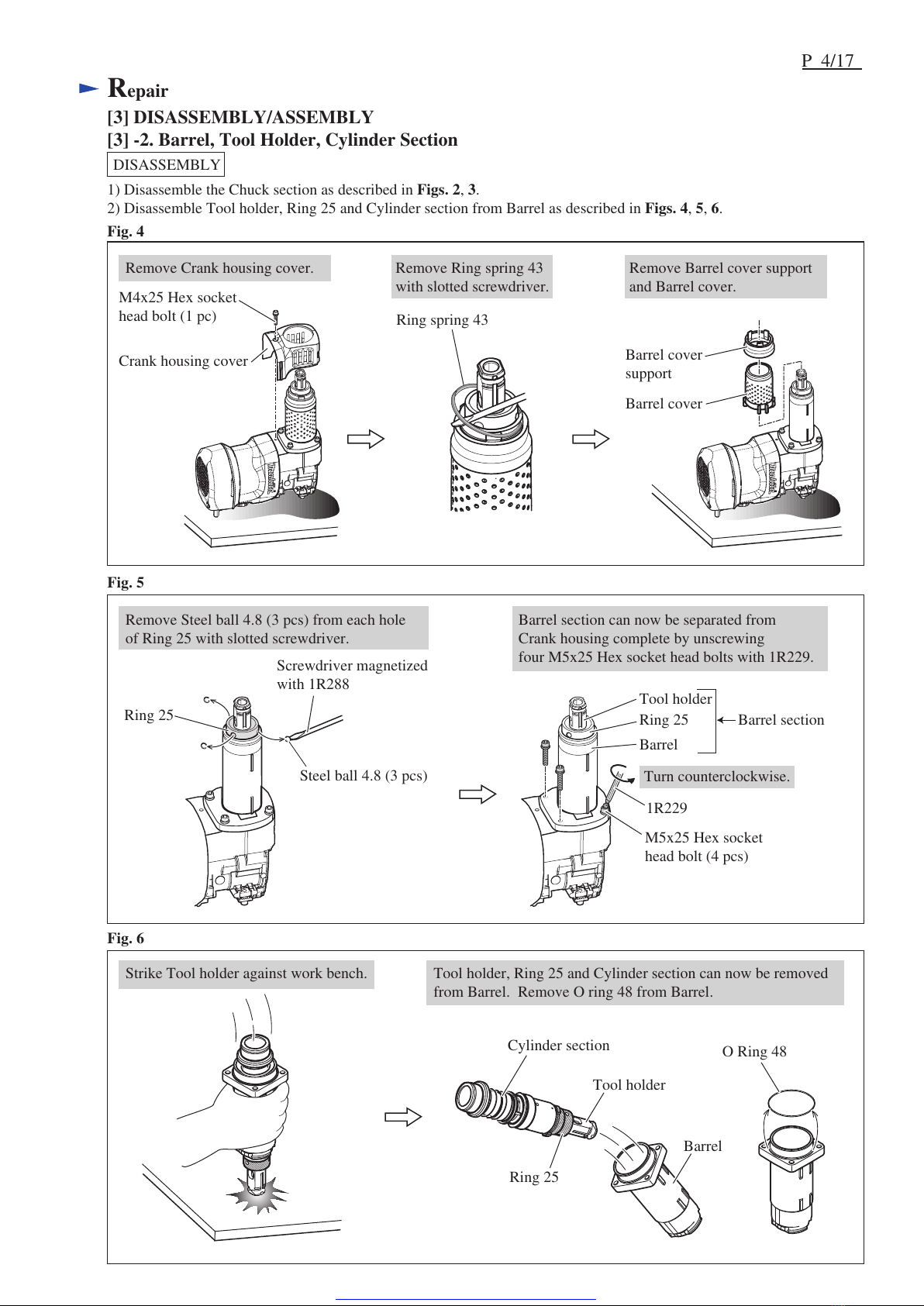
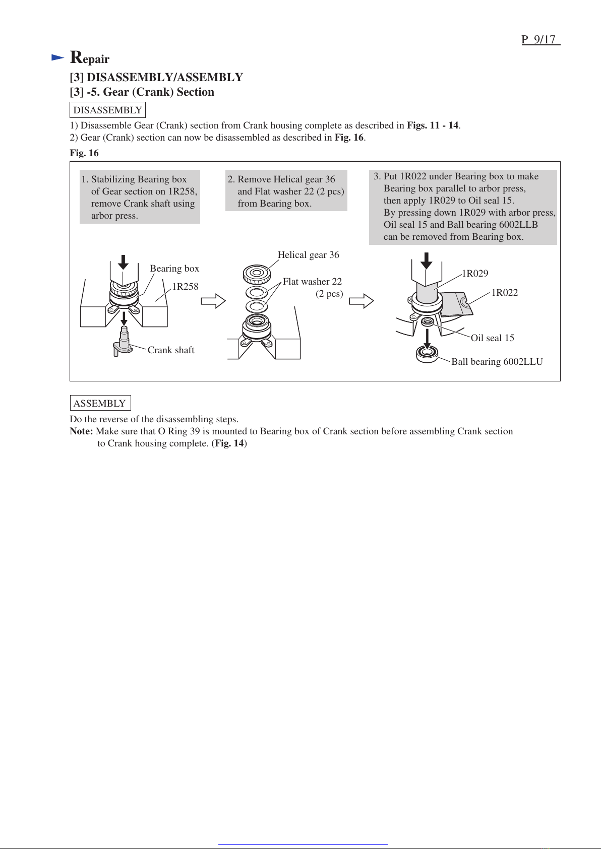
Repair
DescriptionCode No. Use for
Item No. Description Portion to lubricate
1R003
1R022
1R023
1R029
1R212
1R228
1R229
1R258
1R288
Retaining ring pliers ST-2N
Bearing plate
Pipe ring
Bearing setting pipe 23-15.2
Tip for retaining ring pliers
1/4" Hex shank bit for M4
1/4" Hex shank bit for M5
V Block
Screwdriver magnetizer
Removing/mounting Ring spring
Stabilizing Bearing box when removing Ball bearing 6002LLU
Stabilizing Crank housing complete when removing Armature
Removing Oil seal 15 and Ball bearing 6002LLU from Bearing box
Removing/mounting Ring spring (for modular use with 1R003)
1R225 Bearing extractor Removing Armature and Ball bearing 6001DDW from Crank housing comp.
Removing M4x25 Hex socket head bolt from Crank housing cover
Removing M5x25 Hex socket head bolt from Barrel
Stabilizing Bearing box when removing Helical gear 36
Magnetizing Screwdriver when removing Steel balls and Pins
Ring 25 Impact bolt
Tool holder
Compression spring 32
23 27
7
Striker
30
Piston
Connecting rod
38
68
37
27 O Ring 12 Whole portion
Cylinder Inside surface that Piston and Striker contacts
Whole portion
30
7 Steel ball 4.8 (3 pcs) Whole portion
23 Steel Ball 7.0 (2 pcs) Whole portion
37 O Ring 18 on Striker
O Ring 18 on Piston Whole portion
38
32
32 Ring 29 Inside periphery that contacts 30 Cylinder
3g
17g
4g
39 Pin 7 Cylindrical surface that contacts Connecting rod
Flat washer 22
Crank housing complete Crank room
Whole portion for smooth rotation
of Helical gear 36
58 59
61
68 Armature Gear portion for smooth rotation
of Helical gear 36
39
AmountLubricant
Makita grease
N.No.2
Makita grease
N.No.1
Makita grease
R.No.00
a little
a little
a little
Crank shaft
Bearing box
Helical gear 36
58
59
61
23
a little