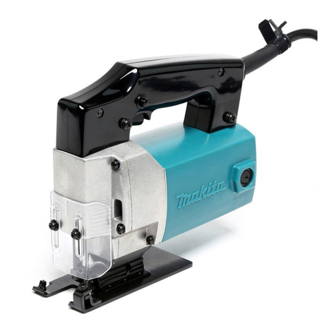
Makita SG1250 User manual

1
GB Wall Chaser INSTRUCTION MANUAL
UA Штроборіз ІНСТРУКЦІЯ ЗЕКСПЛУАТАЦІЇ
PL Bruzdownica INSTRUKCJA OBSŁUGI
RO Maşinăde tăiat canale în zidărie MANUAL DE INSTRUCŢIUNI
DE Mauernutfräse BEDIENUNGSANLEITUNG
HU Falhoronymaró HASZNÁLATI KÉZIKÖNYV
SK Drážkovacia fréza do muriva NÁVOD NA OBSLUHU
CZ Drážkovací frézka zdiva NÁVOD K OBSLUZE
SG1250

2
1
1 004496
1
2 004497
1
2
3 004498
1
4 004499
1
5 004500
1
2
6 004501
1
2
3
7
004502
12
8 004504
1
2
9 004505

3
1
2
3
10 004507
1
2
11 004508
1
12 004509
1
2
13 004510

4
ENGLISH (Original instructions)
Explanation of general view
1-1. Shaft lock
2-1. Notch
3-1. Scale
3-2. Clamping screw
4-1. Slide switch
5-1. Hex socket head bolt
6-1. Blade case
6-2. Base
7-1. Shaft lock button
7-2. Lock nut
7-3. Lock nut wrench
8-1. Diamond wheel
8-2. Blade case
9-1. Front handle
9-2. Hex socket head bolt
10-1. Dust nozzle
10-2. Vacuum cleaner
10-3. Hose
11-1. Hex wrench
11-2. Front handle
12-1. Base
13-1. Inhalation vent
13-2. Exhaust vent
SPECIFICATIONS
Model SG1250
Wheel diameter 125 mm
European countries 10000(min-1)
Rated speed (n) /
No load speed (n0) Other countries 9000(min-1)
Spindle thread M14
Overall length 346 mm
Net weight 4.4 kg
Safety class /II
• Due to our continuing programme of research and development, the specifications herein are subject to change without notice.
• Specifications may differ from country to country.
• Weight according to EPTA-Procedure 01/2003
ENE026-1
Intended use
The tool is intended for cutting tracks in concrete walls or
cutting in ferrous materials or concrete drainage
channels with a diamond wheel but without using water.
ENF002-2
Power supply
The tool should be connected only to a power supply of
the same voltage as indicated on the nameplate, and can
only be operated on single-phase AC supply. They are
double-insulated and can, therefore, also be used from
sockets without earth wire.
ENG905-1
Noise
The typical A-weighted noise level determined according
to EN60745:
Sound pressure level (LpA) : 102 dB(A)
Sound power level (LWA) : 113 dB(A)
Uncertainty (K) : 3 dB(A)
Wear ear protection
ENG900-1
Vibration
The vibration total value (tri-axial vector sum) determined
according to EN60745:
Work mode : concrete cutting
Vibration emission (ah) : 4.0 m/s2
Uncertainty (K) : 1.5 m/s2
ENG901-1
• The declared vibration emission value has been
measured in accordance with the standard test
method and may be used for comparing one tool
with another.
• The declared vibration emission value may also be
used in a preliminary assessment of exposure.
WARNING:
• The vibration emission during actual use of the
power tool can differ from the declared emission
value depending on the ways in which the tool is
used.
• Be sure to identify safety measures to protect the
operator that are based on an estimation of
exposure in the actual conditions of use (taking
account of all parts of the operating cycle such as
the times when the tool is switched off and when it
is running idle in addition to the trigger time).
ENH101-15
For European countries only
EC Declaration of Conformity
We Makita Corporation as the responsible
manufacturer declare that the following Makita
machine(s):
Designation of Machine:
Wall Chaser
Model No./ Type: SG1250
are of series production and

5
Conforms to the following European Directives:
2006/42/EC
And are manufactured in accordance with the following
standards or standardised documents:
EN60745
The technical documentation is kept by our authorised
representative in Europe who is:
Makita International Europe Ltd.
Michigan Drive, Tongwell,
Milton Keynes, Bucks MK15 8JD, England
30.1.2009
000230
Tomoyasu Kato
Director
Makita Corporation
3-11-8, Sumiyoshi-cho,
Anjo, Aichi, 446-8502, JAPAN
GEA010-1
General Power Tool Safety
Warnings
WARNING Read all safety warnings and all
instructions. Failure to follow the warnings and
instructions may result in electric shock, fire and/or
serious injury.
Save all warnings and instructions for
future reference.
GEB042-3
ANGLE CUTTER SAFETY
WARNINGS
Safety Warnings Common for Abrasive Cutting-Off
Operations:
1. This power tool is intended to function as a
cut-off tool. Read all safety warnings,
instructions, illustrations and specifications
provided with this power tool. Failure to follow
all instructions listed below may result in electric
shock, fire and/or serious injury.
2. Operations such as grinding, wire brushing,
polishing are not recommended to be
performed with this power tool. Operations for
which the power tool was not designed may create
a hazard and cause personal injury.
3. Do not use accessories which are not
specifically designed and recommended by
the tool manufacturer. Just because the
accessory can be attached to your power tool, it
does not assure safe operation.
4. The rated speed of the accessory must be at
least equal to the maximum speed marked on
the power tool. Accessories running faster than
their rated speed can break and fly apart.
5. The outside diameter and the thickness of
your accessory must be within the capacity
rating of your power tool. Incorrectly sized
accessories cannot be adequately guarded or
controlled.
6. The arbour size of wheels, flanges, backing
pads or any other accessory must properly fit
the spindle of the power tool. Accessories with
arbour holes that do not match the mounting
hardware of the power tool will run out of balance,
vibrate excessively and may cause loss of control.
7. Do not use a damaged accessory. Before each
use inspect the accessory such as abrasive
wheels for chips and cracks, backing pad for
cracks, tear or excess wear, wire brush for
loose or cracked wires. If power tool or
accessory is dropped, inspect for damage or
install an undamaged accessory. After
inspecting and installing an accessory,
position yourself and bystanders away from
the plane of the rotating accessory and run the
power tool at maximum no-load speed for one
minute. Damaged accessories will normally break
apart during this test time.
8. Wear personal protective equipment.
Depending on application, use face shield,
safety goggles or safety glasses. As
appropriate, wear dust mask, hearing
protectors, gloves and workshop apron
capable of stopping small abrasive or
workpiece fragments. The eye protection must
be capable of stopping flying debris generated by
various operations . The dust mask or respirator
must be capable of filtrating particles generated by
your operation. Prolonged exposure to high
intensity noise may cause hearing loss.
9. Keep bystanders a safe distance away from
work area. Anyone entering the work area
must wear personal protective equipment.
Fragments of workpiece or of a broken accessory
may fly away and cause injury beyond immediate
area of operation.
10. Hold power tool by insulated gripping
surfaces only, when performing an operation
where the cutting accessory may contact
hidden wiring or its own cord. Cutting
accessory contacting a "live" wire may make
exposed metal parts of the power tool "live" and
shock the operator.
11. Position the cord clear of the spinning
accessory. If you lose control, the cord may be cut
or snagged and your hand or arm may be pulled
into the spinning accessory.
12. Never lay the power tool down until the
accessory has come to a complete stop. The
spinning accessory may grab the surface and pull
the power tool out of your control.

6
13. Do not run the power tool while carrying it at
your side. Accidental contact with the spinning
accessory could snag your clothing, pulling the
accessory into your body.
14. Regularly clean the power tool’s air vents. The
motor’s fan will draw the dust inside the housing
and excessive accumulation of powdered metal
may cause electrical hazards.
15. Do not operate the power tool near flammable
materials. Sparks could ignite these materials.
16. Do not use accessories that require liquid
coolants. Using water or other liquid coolants may
result in electrocution or shock.
Kickback and Related Warnings
Kickback is a sudden reaction to a pinched or snagged
rotating wheel, backing pad, brush or any other accessory.
Pinching or snagging causes rapid stalling of the rotating
accessory which in turn causes the uncontrolled power
tool to be forced in the direction opposite of the
accessory’s rotation at the point of the binding.
For example, if an abrasive wheel is snagged or pinched
by the workpiece, the edge of the wheel that is entering
into the pinch point can dig into the surface of the
material causing the wheel to climb out or kick out. The
wheel may either jump toward or away from the operator,
depending on direction of the wheel’s movement at the
point of pinching. Abrasive wheels may also break under
these conditions.
Kickback is the result of power tool misuse and/or
incorrect operating procedures or conditions and can be
avoided by taking proper precautions as given below.
a) Maintain a firm grip on the power tool and
position your body and arm to allow you to
resist kickback forces. Always use auxiliary
handle, if provided, for maximum control over
kickback or torque reaction during start-up.
The operator can control torque reactions or
kickback forces, if proper precautions are taken.
b)
Never place your hand near the rotating
accessory.
Accessory may kickback over your hand.
c) Do not position your body in the area where
power tool will move if kickback occurs.
Kickback will propel the tool in direction opposite to
the wheel’s movement at the point of snagging.
d) Use special care when working corners,
sharp edges etc. Avoid bouncing and snagging
the accessory. Corners, sharp edges or bouncing
have a tendency to snag the rotating accessory and
cause loss of control or kickback.
e) Do not attach a saw chain woodcarving
blade or toothed saw blade. Such blades create
frequent kickback and loss of control
Safety Warnings Specific for Abrasive Cutting-Off
Operations:
a) Use only wheel types that are recommended
for your power tool and the specific guard
designed for the selected wheel. Wheels for
which the power tool was not designed cannot be
adequately guarded and are unsafe.
b) The guard must be securely attached to the
power tool and positioned for maximum safety,
so the least amount of wheel is exposed
towards the operator. The guard helps to protect
operator from broken wheel fragments and
accidental contact with wheel.
c) Wheels must be used only for recommended
applications. For example: do not grind with
the side of cut-off wheel. Abrasive cut-off wheels
are intended for peripheral grinding, side forces
applied to these wheels may cause them to shatter.
d) Always use undamaged wheel flanges that
are of correct size and shape for your selected
wheel. Proper wheel flanges support the wheel
thus reducing the possibility of wheel breakage.
Flanges for cut-off wheels may be different from
grinding wheel flanges.
e) Do not use worn down wheels from larger
power tools. Wheel intended for larger power tool
is not suitable for the higher speed of a smaller tool
and may burst.
Additional Safety Warnings Specific for Abrasive
Cutting-Off Operations:
a) Do not “jam” the cut-off wheel or apply
excessive pressure. Do not attempt to make an
excessive depth of cut. Overstressing the wheel
increases the loading and susceptibility to twisting
or binding of the wheel in the cut and the possibility
of kickback or wheel breakage.
b) Do not position your body in line with and
behind the rotating wheel. When the wheel, at
the point of operation, is moving away from your
body, the possible kickback may propel the
spinning wheel and the power tool directly at you.
c) When wheel is binding or when interrupting a
cut for any reason, switch off the power tool
and hold the power tool motionless until the
wheel comes to a complete stop. Never attempt
to remove the cut-off wheel from the cut while
the wheel is in motion otherwise kickback may
occur. Investigate and take corrective action to
eliminate the cause of wheel binding
d) Do not restart the cutting operation in the
workpiece. Let the wheel reach full speed and
carefully reenter the cut. The wheel may bind,
walk up or kickback if the power tool is restarted in
the workpiece.
e) Support panels or any oversized workpiece
to minimize the risk of wheel pinching and
kickback. Large workpieces tend to sag under
their own weight. Supports must be placed under
the workpiece near the line of cut and near the
edge of the workpiece on both sides of the wheel.
f) Use extra caution when making a “pocket
cut” into existing walls or other blind areas.
The protruding wheel may cut gas or water pipes,
electrical wiring or objects that can cause kickback.

7
Additional safety warnings:
17. Be careful not to damage the spindle, the
flange (especially the installing surface) or the
lock nut. Damage to these parts could result in
wheel breakage.
18. Make sure the wheel is not contacting the
workpiece before the switch is turned on.
19. Before using the tool on an actual workpiece,
let it run for a while. Watch for vibration or
wobbling that could indicate poor installation
or a poorly balanced wheel.
20. Watch out for flying sparks. Hold the tool so
that sparks fly away from you and other
persons or flammable materials.
21. Do not leave the tool running. Operate the tool
only when hand-held.
22. Do not touch the workpiece immediately after
operation; it may be extremely hot and could
burn your skin.
23. Always be sure that the tool is switched off
and unplugged or that the battery cartridge is
removed before carrying out any work on the
tool.
24. Observe the instructions of the manufacturer
for correct mounting and use of wheels.
Handle and store wheels with care.
25. Do not use separate reducing bushings or
adaptors to adapt large hole abrasive wheels.
26. Use only flanges specified for this tool.
27. Check that the workpiece is properly
supported.
28. Pay attention that the wheel continues to
rotate after the tool is switched off.
29. If working place is extremely hot and humid,
or badly polluted by conductive dust, use a
short-circuit breaker (30 mA) to assure
operator safety.
30. Do not use the tool on any materials
containing asbestos.
31. Do not use water or grinding lubricant.
32. Ensure that ventilation openings are kept clear
when working in dusty conditions. If it should
become necessary to clear dust, first
disconnect the tool from the mains supply
( use non metallic objects ) and avoid
damaging internal parts.
33. Cutting discs must not be subjected to any
lateral pressure.
SAVE THESE INSTRUCTIONS.
WARNING:
DO NOT let comfort or familiarity with product
(gained from repeated use) replace strict adherence
to safety rules for the subject product. MISUSE or
failure to follow the safety rules stated in this
instruction manual may cause serious personal
injury.
FUNCTIONAL DESCRIPTION
CAUTION:
• Always be sure that the tool is switched off and
unplugged before adjusting or checking function on
the tool.
Shaft lock
Fig.1
CAUTION:
• Never actuate the shaft lock when the spindle is
moving. The tool may be damaged.
Press the shaft lock to prevent spindle rotation when
installing or removing accessories.
Sighting
Fig.2
There are notches on the front and rear of the base. This
is helpful for an operator to follow a straight cutting line.
Adjusting the grooving or cutting depth
Fig.3
The depth of grooving or cutting can be adjusted in the
range of 0 through 30 mm.
Loosen and move the clamping screw so that the pointer
points to your desired depth graduation on the scale.
Then tighten the clamping screw firmly.
Switch action
Fig.4
CAUTION:
• Before plugging in the tool, always check to see
that the slide switch actuates properly and returns
to the "OFF" position when the rear of the slide
switch is depressed.
To start the tool, slide the slide switch toward the "I (ON)"
position. For continuous operation, press the front of the
slide switch to lock it.
To stop the tool, press the rear of the slide switch, then
slide it toward the "O (OFF)" position.
Electronic function
The tools equipped with electronic function are easy to
operate because of the following features.
Constant speed control
Electronic speed control for obtaining constant speed.
Possible to get fine finish, because the rotating speed is
kept constant even under load condition.
Soft start
Soft-start feature minimizes start-up shock, and makes
the tool start smoothly.
Overload protector
When the tool would be employed over the admissible
load, it will stop automatically to protect the motor and
wheel. When the load will come to the admissible level
again, the tool can be started automatically.

8
ASSEMBLY
CAUTION:
•
Always be sure that the tool is switched off and
unplugged before carrying out any work on the tool.
Installing or removing the diamond wheel
Removal
Fig.5
Loosen and remove the bolt with the hex wrench.
Open the cover while holding the tool base with a hand
as shown in the figure.
Fig.6
NOTE:
• The tool base will open at a stroke by the spring
force.
Rotate the diamond wheel while pressing the shaft lock
until it engages.
Fig.7
Remove the lock nut by rotating it counterclockwise with
the lock nut wrench.
Remove the diamond wheel and space rings.
Adjusting the groove width (the distance between
the two diamond wheels)
The width of grooving in the workpiece can be adjusted
by changing the number of the space rings as shown in
the table.
1
2
3
4
5
Groove width: 30 mm
Groove width: 18 mm Groove width: 15 mm
Groove width: 27 mm
Groove width: 24 mm
Groove width: 9 mm
Groove width: 6 mm
Groove width: 21 mm
Groove width: 12 mm
004503
INSTALLATION
Fig.8
Determine the distance of the two blades according to
the table.
To install the diamond wheel, mount it carefully onto the
spindle, making sure that the direction of the arrow on the
surface of the diamond wheel matches the direction of
the arrow on the tool. Install space ring and lock nut.
Tighten the lock nut securely clockwise with the lock nut
wrench while pushing down the shaft lock.
Return the cover and the base to the original position and
tighten the bolt to secure them.
1. Lock nut
2. Diamond wheel
3. Space ring 6 (6 mm thick)
4. Space ring 3 (3 mm thick)
5. Diamond wheel

9
Front handle
Fig.9
1. The angle of installation of the front handle is
changeable.
• To change its position, loosen the two bolts on both
sides of the front handle with the hex wrench and
move the front handle to your desired position.
NOTE:
• When the handle cannot be moved easily, loosen
the bolts furthermore.
• To secure the handle, tighten the two bolts firmly.
2. The front handle can be shifted sideways.
134
256
004506
• To shift it, loosen and remove the two bolts on both
sides of the front handle.
• Remove the cam and install it on the opposite side
as shown in the figure.
• Insert the longer bolt to the hole in the handle on
the side close to the installed cam and the shorter
bolt on the opposite side.
• Then tighten the two bolts firmly.
Connecting to vacuum cleaner
Fig.10
When you wish to perform cleaner operation, connect a
vacuum cleaner to your tool. Connect a hose of vacuum
cleaner to the dust nozzle.
NOTE:
• The dust nozzle can be rotated freely so that you
can use it at any angle according to your operation.
Hex wrench storage
Fig.11
When not in use, store the hex wrench as shown in the
figure to keep it from being lost.
OPERATION
CAUTION:
• Be sure to pull the tool when cutting a workpiece.
• Use this tool for straight line cutting only. Cutting
curves can cause stress cracks or fragmentation of
the diamond wheel resulting in possible injury to
persons in the vicinity.
• After operation, always switch off the tool and wait
until the wheel has come to a complete stop before
putting the tool down.
• Always use the front grip and firmly hold the tool by
both front grip and main handle during operations.
Adjust the front handle to appropriate position for your
work by referring to the "Front handle " in the section
"ASSEMBLY".
Hold the tool firmly with both hands. First keep the wheel
without making any contact with a workpiece to be cut.
Then turn the tool on and wait until the wheel attains full
speed.
Fig.12
The cut is made by pulling the tool toward you (not by
pushing away from you). Align the notch on the base with
your cutting line, push down the front handle gently until it
stops and then pull the tool slowly to perform a cut.
Switch off the tool in the position posed when finishing a
cut. Raise the tool after the wheel comes to a complete
stop.
Remove the remaining portion between the two blade
passage by other appropriate tools.
MAINTENANCE
CAUTION:
• Always be sure that the tool is switched off and
unplugged before attempting to perform inspection
or maintenance.
• Never use gasoline, benzine, thinner, alcohol or the
like. Discoloration, deformation or cracks may
result.
The tool and its air vents have to be kept clean. Regularly
clean the tool's air vents or whenever the vents start to
become obstructed.
Fig.13
Dressing diamond wheel
If the cutting action of the diamond wheel begins to
diminish, use an old discarded coarse grit bench grinder
wheel or concrete block to dress the diamond wheel. To
do this, tightly secure the bench grinder wheel or
concrete block and cut in it.
To maintain product SAFETY and RELIABILITY, repairs,
carbon brush inspection and replacement, any other
maintenance or adjustment should be performed by
Makita Authorized Service Centers, always using Makita
replacement parts.
1. Hex socket head bolt
2. Cam
3. Hex socket head bolt
4. Hex socket head bolt
5. Cam
6. Hex socket head bolt

10
OPTIONAL ACCESSORIES
CAUTION:
• These accessories or attachments are
recommended for use with your Makita tool
specified in this manual. The use of any other
accessories or attachments might present a risk of
injury to persons. Only use accessory or
attachment for its stated purpose.
If you need any assistance for more details regarding
these accessories, ask your local Makita Service Center.
• Diamond wheels
NOTE:
• Some items in the list may be included in the tool
package as standard accessories. They may differ
from country to country.

11
УКРАЇНСЬКА (Оригінальні інструкції)
Пояснення до загального виду
1-1. Фіксатор
2-1. Прорізь
3-1. Масштаб
3-2. Затискний гвинт
4-1. Повзунковий перемикач
5-1. Болт із внутрішньою
шестигранною голівкою
6-1. Корпус диску
6-2. Основа
7-1. Кнопка блокування вала
7-2. Контргайка
7-3. Ключ для контргайки
8-1. Алмазний диск
8-2. Корпус диску
9-1. Передня ручка
9-2. Болт із внутрішньою
шестигранною голівкою
10-1. Штуцер для пилу
10-2. Пилосос
10-3. Шланг
11-1. Шестигранний ключ
11-2. Передня ручка
12-1. Основа
13-1. Вдихальний клапан
13-2. Повітровідвід
ТЕХНІЧНІ ХАРАКТЕРИСТИКИ
Модель SG1250
Діаметр диска 125 мм
Європейські країни 10000 (хв.-1)
Номінальна швидкість (n) /
Швидкість без навантаження (n
0
)
Інші країни 9000 (хв.-1)
Різьба шпинделя M14
Загальна довжина 346 мм
Чиста вага 4,4 кг
Клас безпеки /II
• Через те, що ми не припиняємо програми досліджень ірозвитку, наведені тут технічні характеристики можуть бути змінені
без попередження.
• Урізних країнах технічні характеристики можуть бути різними.
• Вага відповідно до EPTA-Procedure 01/2003
ENE026-1
Призначення
Інструмент призначено для прорізання канавок у
бетонних стінах або стічних каналів уметалевих та
бетонних матеріалах за допомогою алмазного кола,
але без застосування води.
ENF002-2
Джерело живлення
Інструмент можна підключати лише до джерела
живлення, що має напругу, зазначену втабличці із
заводськими характеристиками, івін може працювати
лише від однофазного джерела змінного струму. Він
має подвійну ізоляцію, аотже може також
підключатися до розеток без дроту заземлення.
ENG905-1
Шум
Рівень шуму за шкалою Аутиповому виконанні,
визначений відповідно до EN60745:
Рівень звукового тиску (LpA): 102 дБ(A)
Рівень акустичної потужності (LWA): 113 дБ(A)
Похибка (K) : 3 дБ(A)
Користуйтеся засобами захисту слуху
ENG900-1
Вібрація
Загальна величина вібрації (сума трьох векторів)
визначена згідно зEN60745:
Режим роботи: різання бетону
Вібрація (aгод) : 4,0 м/с2
Похибка (К): 1,5 м/с2
ENG901-1
• Заявлене значення вібрації було виміряно у
відповідності до стандартних методів
тестування та може використовуватися для
порівняння одного інструмента зіншим.
• Заявлене значення вібрації може також
використовуватися для попередньої оцінки
впливу.
УВАГА:
• Залежно від умов використання вібрація під час
фактичної роботи інструмента може
відрізнятися від заявленого значення вібрації.
• Забезпечте належні запобіжні заходи для
захисту оператора, що відповідатимуть умовам
використання інструмента (слід брати до уваги
всі складові робочого циклу, такі як час, коли
інструмент вимкнено та коли він починає
працювати на холостому ході під час запуску).

12
ENH101-15
Тільки для країн Європи
Декларація про відповідність стандартам
ЄС
Наша компанія, Makita Corporation, як
відповідальний виробник, наголошує на тому, що
обладнання Makita:
Позначення обладнання:
Штроборіз
№моделі/ тип: SG1250
єсерійним виробництвом та
Відповідає таким Європейським Директивам:
2006/42/EC
Та вироблені увідповідності до таких стандартів та
стандартизованих документів:
EN60745
Технічна документація знаходиться унашого
уповноваженого представника вЄвропі, асаме:
Makita International Europe Ltd.
Michigan Drive, Tongwell,
Milton Keynes, Bucks MK15 8JD, Англія
30.1.2009
000230
Tomoyasu Kato
Директор
Makita Corporation
3-11-8, Sumiyoshi-cho,
Anjo, Aichi, 446-8502, ЯПОНІЯ
GEA010-1
Застереження стосовно техніки
безпеки при роботі з
електроприладами
УВАГА! Прочитайте усі застереження
стосовно техніки безпеки та всі інструкції.
Недотримання даних застережень та інструкцій може
призвести до ураження струмом та виникнення
пожежі та/або серйозних травм.
Збережіть усі інструкції зтехніки
безпеки та експлуатації на майбутнє.
GEB042-3
ПОПЕРЕДЖЕННЯ ПРО
НЕОБХІДНУ ОБЕРЕЖНІСТЬ ПІД
ЧАС РОБОТИ ЗКУТОВОЮ
ВІДРІЗНОЮ МАШИНОЮ
Попередження про небезпеку, що єзагальними
для операцій абразивного різання:
1. Цей електроінструмент призначений для
різання. Уважно ознайомтеся зусіма
попередженнями відносно безпечного
використання, інструкціями, ілюстраціями
та технічними характеристиками цього
електроінструменту.Невиконання цих
інструкцій може призвести до ураження
електричним струмом, пожежі та/або
серйозного поранення.
2. За допомогою цього інструменту не
рекомендується виконувати такі операції,
як шліфування, чищення за допомогою
дротяної щітки та полірування.
Використання інструменту не за призначенням
може спричинити небезпечну ситуацію та
призвести до поранення.
3. Не слід використовувати допоміжні
приналежності, які спеціально не
призначені та не рекомендовані для цього
інструменту виробником.Навіть якщо вони
добре приєднуються до інструменту, це не
гарантує небезпечної експлуатації.
4. Номінальна швидкість допоміжних
пристроїв повинна щонайменш
дорівнюватися максимальній швидкості,
що відзначена на електроінструменті.
Допоміжні пристрої, що працюють швидше
своєї номінальної скорості можуть поламатися
та відскочити.
5. Зовнішній діаметр та товщина вашого
допоміжного приладу повинні бути умежах
паспортної потужності вашого
електроінструменту.Приладдя неналежних
розмірів не можна захистити або контролювати
належним чином.
6. Розмір штока дисків, фланців, підкладок
або будь-яких інших при належностей
повинен підходити для шпинделя
інструмента.Приналежності із отворами під
шпиндель, що не підходять під кріплення
інструмента будуть розбалансовані, матимуть
надмірну вібрацію та можуть призвести до
втрати контролю.
7. Не слід користуватися пошкодженим
приладдям Перед кожним використанням
слід перевірити приналежність, таку як
абразивні диски, на наявність сколів або
тріщин, зносу, аметалеві щітки - на
наявність послабленого або тріснутого
дроту. Уразі падіння інструменту або
приладдя, слід оглянути їх на наявність
пошкоджень або встановити неушкоджене
приладдя. Після огляду та встановлення
приналежності, слід зайняти таке
положення, коли ви та ваші сусіди
знаходяться на відстані від площини
приладу, що обертається, запустіть
інструмент та дайте йому попрацювати на
максимальній швидкості без навантаження
протягом однієї хвилини.Під час цього
пробного прогону приналежності прилади, як

13
правило, розбиваються.
8. Слід одягати засоби індивідуального
захисту. Слід користуватися
щитком-маскою, захисними окулярами або
захисними лінзами відповідно до області
застосування. Це означає, що слід одягати
пилозахисну маску, засоби захисту органів
слуху, рукавиці та фартух, які здатні
затримувати дрібні частки деталі та
наждаку.Засоби захисту органів зору повинні
бути здатними затримувати сміття, що
утворюється під час виконання різних операцій.
Пилозахисна маска або респіратор повинні
бути здатними фільтрувати часточки, що
утворюються під час роботи. Тривалий вплив
сильного шуму може призвести до втрати
слуху.
9. Спостерігачі повинні знаходитися на
небезпечному відстані від місця роботи.
Кожний, хто приходить вробочу зону
повинен одягати засоби індивідуального
захисту.Частки деталі або уламки приладдя
може відлетіти за межі безпосередньої зони
роботи та поранити.
10. Під час різання, коли ріжучий інструмент
може торкнутися схованої електропроводки
або свого шнуру, інструмент слід тримати
за ізольовані поверхні держака.Торкання
ріжучим приладом струмоведучої проводки
може призвести до передання напруги до
металевих частин інструменту та ураженню
електричним струмом оператора.
11. Шнур слід розміщувати без змотуючого
пристрою.Якщо ви втратите контроль, шнур
може бути перерізаним або пошкодженим та
ваша рука може потрапити до змотуючого
пристрою.
12. Не слід класти інструмент доки прилад
повністю не зупиниться.Змотуючий пристрій
може захопити шнур та вирвати його з-під
контролю.
13. Не слід запускати інструмент, коли ви його
тримаєте збоку себе.Випадкове стикання зі
змотуючим пристроєм може захопити ваш одяг,
що всвою чергу може призвести до штовхання
приладу до вас.
14. Слід регулярно чистити вентиляційні
отвори інструменту. Вентилятор двигуна
втягує пил усередину кожуха та надмірне
скупчення металевого порошку створює ризик
ураження електричним струмом.
15. Не слід працювати біля займистих
матеріалів.Вони можуть спалахнути від іскри.
16. Не слід застосовувати допоміжне приладдя,
що потребує рідких охолоджувачів.
Використання води, або рідких охолоджувачів
може призвести по ураження електричним
струмом або смерті.
Віддача та відповідні попереджувальні заходи
Віддача це несподівана реакція на защемлення,
чіпляння поворотного кола, підкладки, щітки або
якогось іншої приналежності. Защемлення або
чіпляння призводять до швидкої зупинки поворотної
приналежності, що всвою чергу спричиняє до
неконтрольованого спонукання інструменту у
протилежному напрямку від обертання
приналежності умісці заїдання.
Наприклад, якщо абразивне коло защемлене або
зачеплене деталлю, край кола, що входить до місця
защемлення може зануритися вповерхню матеріалу,
що призведе до зіскок кола та віддачі. Коло може
відскочити до або від оператора, це залежить від
напрямку руху кола вмісці защемлення. За таких
умов абразивні кола можуть поламатися.
Причинами віддачі єнеправильне користування
інструментом та/або неправильний порядок
експлуатації або умови експлуатації, та їх можна
уникнути дотримуючись запобіжних заходів, що
наведені нижче:
a) Міцно тримай держак на інструменті та
займи таке положення, при якому зможеш
протистояти зусиллям віддачі. Завжди
користайся допоміжною ручкою, якщо є,
щоб збільшити до максимуму контроль над
віддачею або реакцією крутного моменту під
час пуску.Якщо додержуватися усіх запобіжних
заходів, оператор зможе контролювати реакції
крутного моменту або зусилля віддачі.
b) Ніколи не слід розміщувати руку біля
приналежності, що обертається.Вона може
відскочити на руку.
c) Не слід стояти взоні, куди посунеться
інструмент під час віддачі.Віддача
спонукатиме інструмент упротилежному
напрямку до напрямку руху кола вмісці
защемлення.
d) Слід бути особливо пильним під час
обробки кутів, гострих країв іт.д. Уникайте
коливання та чіпляння приналежності Кути,
гострі краї або коливання мають тенденцію до
чіпляння приналежності, що обертається, що в
свою чергу призводить до втрати контролю та
віддачі.
e) Заборонено встановлювати пильний
ланцюг, полотно для різьби по дереву або
полотно зубчастої пили.такі полотна
створюють часту віддачу та призводять до
втрати контролю
Попередження про небезпеку, що єспецифічними
для операцій абразивного різання:
a) Використовуйте тільки типи дисків, які
рекомендовані для вашого інструмента, а
також спеціальний кожух під обраний диск.
Диски, на які інструмент не розрахований, не
можуть бути надійно закріплені та є
небезпечними.

14
b) Кожух повинен бути надійно закріплений
на інструменті та розташований
максимально безпечно, щоб для оператора
диск був якомога менше відкритим.Кожух
допомагає захищати оператора від осколків
зламаного диска та від випадкового контакту з
диском.
c) Диски слід використовувати тільки за їх
рекомендованим призначенням. Наприклад:
Не слід шліфувати бічною стороною
відрізного диска.Абразивні відрізні диски
призначені для шліфування периферією диска,
при прикладанні бічних зусиль до цих дисків,
вони можуть розбитися.
d) Слід завжди використовувати
неушкоджені фланці диска, розмір та форми
яких відповідають обраному диску Належні
фланці добре утримують диск, йтаким чином
зменшують ймовірність поломки диска. Фланці
для відрізних дисків можуть відрізнятись від
фланців шліфувальних дисків.
e) Не слід використовувати зношені диски
більших інструментів.Диск, що призначений
для більшого інструменту не підходить до вищої
скорості меншого інструменту та може
розірватися.
Додаткоів попередження про небезпеку загальні
для операцій полірування та абразивного
різання:
a) Не можна «заклинювати» відрізний диск
або прикладати надмірний тиск. Не слід
намагатись зробити проріз надмірної
глибини.Перенапруга диска збільшує
навантаження та схильність до перекошування
або застрявання диска впрорізі, атакож
створює можливість віддачі або поломки диска.
b) Неможна розташовуватись на одній лінії
та позадо диска, що обертається.Коли під час
роботи диск рухається від вас, то можлива
віддача може відкинути диск, що обертається, та
інструмент прямо увас.
c) Коли диск застряє або коли різання з
будь-яких причин переривається, слід
вимкнути інструмент та тримати його на
одному місці, доки диск повністю не
зупиниться. Неможна намагатись вийняти
відрізний диск зпрорізу, коли він рухається,
тому що це може призвести до віддачі.Слід
перевірити та вжии належних заходів, щоб
усунути причину застрявання диска
d) Заборонено заново запускати операцію
різання, коли диск знаходиться вдеталі.
Спочатку диск повинен набрати повної
швидкості, апотім його слід обережно
повернути впроріз.Якщо інструмент
перезапустити, коли диск знаходиться вдеталі,
диск може застряти, підкинутись або спричинити
віддачу.
e) Слід великі панелі або деталі великого
розміру для того, щоб мінімізувати ризик
защемлення полотна або віддачі.Великі
деталі прогинаються під своєю вагою. Опори
слід встановити під деталь біля лінії різання та
біля краю деталі панелі зобох сторін диска.
f) Зособливою обережністю слід виконувати
"врізання" віснуючі стіни або інші невидимі
зони.Виступаючий диск може зіткнутися з
предметами, що спричинять віддачу.
Додаткові попередження про безпеку:
17. Не пошкоджуйте шпиндель, фланець
(особливо поверхню встановлення) або
контргайку. Пошкодження цих частин може
призвести до поломки диска.
18. Перевірте, щоб коло не торкалося деталі
перед увімкненням.
19. Перед початком різання деталі, запустіть
інструмент та дайте попрацювати йому
деякий час. Перевірте чи не коливає або не
виляє він, що може вказувати на
неправильне встановлення або
балансування кола.
20. Остерігайтесь іскри. Тримайте інструмент
таким чином, щоб іскри відлітали від вас та
інших людей або займистих матеріалів.
21. Не залишайте інструмент працюючим.
Працюйте зінструментом тільки тоді, коли
тримаєте його вруках.
22. Не торкайтесь деталі одразу після різання,
вона може бути дуже гарячою та призвести
до опіку шкіри.
23. Перед здійсненням будь-яких робіт з
інструментом, завжди перевіряйте, щоб
інструмент було вимкнено та відключено
від мережі або витягнуто касету із
акумулятором.
24. Для того, щоб правильно встановити та
використовувати кола, слід дотримуватись
інструкцій виробника. Слід дбайливо
поводитися та зберігати кола.
25. Не слід використовувати окремі перехідні
втулки або адаптери для пристосування
шліфувальних кіл великого діаметру.
26. Слід застосовувати тільки фланці зазначені
для цього інструменту.
27. Перевірте надійність опори деталі
28. Слід звернути увагу, що коло продовжує
обертатися після вимкнення інструменту
29. Для забезпечення безпеки оператора слід
застосовувати автоматичний вимикач
(30мА), якщо робоче місце надмірно гаряче
та вологе, або дуже забруднюється пилом.
30. Не слід застосовувати інструмент для
роботи зматеріалом, що містить азбест.
31. Не слід застосовувати воду або
мастильний матеріал для шліфування.

15
32. Під час роботи вумовах запиленого
приміщення обов'язково відкривайте
вентиляційні отвори. Якщо необхідно
почистити пил, спочатку відключить
інструмент від мережі (користуйтесь
неметалевими предметами) та будьте
обережними, щоб не пошкодити внутрішні
частини.
33. Не слід надавати бокового тиску на ріжучі
диски
ЗБЕРІГАЙТЕ ЦІ ВКАЗІВКИ
УВАГА:
НІКОЛИ НЕ СЛІД втрачати пильності та
розслаблюватися під час користування виробом
(що приходить при частому використанні); слід
завжди строго дотримуватися правил безпеки під
час використання цього пристрою. НЕНАЛЕЖНЕ
ВИКОРИСТАННЯ або недотримання правил
безпеки, викладених вцьому документі, може
призвести до серйозних травм.
ІНСТРУКЦІЯ ЗВИКОРИСТАННЯ
ОБЕРЕЖНО:
• Перед регулюванням та перевіркою справності
інструменту, переконайтеся втому, що він
вимкнений та відключений від мережі.
Фіксатор
Fig.1
ОБЕРЕЖНО:
• Заборонено використовувати блокування вала,
коли шпиндель обертається. Інструмент може
пошкодитись.
Натисніть на блокування вала для того, щоб
заблокувати обертання шпинделя під час
встановлення або зняття приналежностей.
Виставляння
Fig.2
На задній та передній частині єпрорізі. Вони
допомагають операторові витримувати пряму під час
різання.
Регулювання глибини довбання канавок
або різання.
Fig.3
Глибину довбання канавок або різання можна
регулювати вмежах від 0 до 30 мм.
Послабте та пересуньте затискний гвинт таким чином,
щоб покажчик вказував на мітку необхідної глибини
на шкалі.
Потім міцно затягніть затискний гвинт.
Дія вимикача.
Fig.4
ОБЕРЕЖНО:
• Перед тим, як увімкнути інструмент всіть, слід
завжди перевіряти, щоб повзунок працював
належним чином та повертався уположення
"ВИМК.", коли натискається задня частина
повзункового перемикача.
Для того, щоб запустити інструмент, слід пересунути
повзунковий перемикач вположення "І(ВМК.)". Для
безперервної роботи слід натиснути на передню
частину пересувного перемикача, щоб його
заблокувати.
Для зупинення інструмента слід натиснути на задню
частину пересувного перемикача унапрямку
положення "О(ВИМК.)".
Електронні функції
Інструменти обладнані електронними функціями є
простими вексплуатації завдяки наступним функціям.
Постійний контроль швидкості
Електронне управління швидкістю для забезпечення
постійної швидкості. Дає можливість отримати чисту
обробку, тому ще швидкість обертання підтримується
на постійному рівні, навіть під навантаженням.

16
М'який пуск.
Функція м'якого запуску мінімізує ривок під час пуску
та забезпечує плавний запуск інструмента.
Захисний пристрій від перенавантаження
Коли інструмент використовується із перевищенням
дозволеного навантаження, він автоматично
зупиняється для захисту мотора та диска. Коли
навантаження повертається до дозволенного рівня,
інструмент може автоматично вмикатись.
КОМПЛЕКТУВАННЯ
ОБЕРЕЖНО:
• Перед тим, як зайнятись комплектуванням
інструменту, переконайтеся втому, що він
вимкнений та відключений від мережі.
Встановлення та зняття алмазного диска
Зняття
Fig.5
Послабте та зніміть болт за допомогою
шестигранного ключа.
Підніміть кришку, тримаючи основу інструмента
рукою, як показано на малюнку.
Fig.6
ПРИМІТКА:
• Основа інструмента відкриється під силою
пружини.
Повертайте алмазний диск, натискаючи на
блокування вала, доки його не буде заблоковано.
Fig.7
Зніміть контргайку, повернувши її проти годинникової
стрілки за допомогою ключа для контргайки.
Зніміть алмазне колесо та проставочні кільця.
Регулювання ширини канавки (відстань між
двома алмазними дисками)
Ширину канавки, що ріжеться на деталі, можна
регулювати змінюючи кількість проставочних кілець,
як показано на таблиці.
12
3
4
5
Ширина паза: 30 мм
Ширина паза: 18 мм Ширина паза: 15 мм
Ширина паза: 27 мм
Ширина паза: 24 мм
Ширина паза: 9 мм
Ширина паза: 6 мм
Ширина паза: 21 мм
Ширина паза: 12 мм
004503
ВСТАНОВЛЕННЯ
Fig.8
Визначте відстань між двома лезами згідно таблиці.
Для того, щоб встановити алмазний диск, обережно
вставте його на шпиндель, перевіривши, чи співпадає
напрямок стрілки на поверхні диску знапрямком
стрілки на корпусі інструмента. Встановіть
проставочне кільце та контргайку.
Надійно затягніть контргайку по годинниковій стрілці
за допомогою ключа для контргайок, притискаючи
блокування вала.
Встановіть кришку та основу впочаткове положення
та затягніть болт, щоб їх закріпити.
1. Контргайка
2. Алмазний диск
3. Кільцева проставка 6 (товщиною 6 мм)
4. Кільцева проставка 3 (товщиною 3 мм)
5. Алмазний диск

17
Передня ручка
Fig.9
1. Кут встановлення передньої ручки можна
змінювати.
• Для зміни його положення треба послабити
обидва болти зобох боків передньої ручки за
допомогою шестигранного ключа та пересуньте
передню ручку внеобхідне положення.
ПРИМІТКА:
• Якщо ручка не рухається вільно, слід ще
послабити болти.
• Для того, щоб закріпити ручку, слід міцно
затягнути два болта.
2. Передню ручку можна пересунути вбік.
134
256
004506
• Для того, щоб її пересунути, слід зняти два
болта зобох боків на передній ручці.
• Зніміть кулачок та встановіть його на
протилежну сторону, як показано на малюнку.
• Вставте довший болт вотвір на ручці збоку, зо
ближчий до встановленого кулачка, акоротший
болт вставте зіншого боку.
• Потім міцно затягніть обидва болта.
Підключення пилососа
Fig.10
Якщо ви хочете виконати операції зрізання із
дотриманням чистоти, до інструмента слід
підключити пилосос. Приєднайте шланг пилососа до
штуцера для пилу.
ПРИМІТКА:
• Штуцер для пилу можна вільно обертати, щоб
його можна було використовувати під будь-яким
кутом згідно зцілями роботи.
Зберігання шестигранного ключа
Fig.11
Коли шестигранний ключ не використовується, щоб
він не загубився, його слід зберігати як показано на
малюнку.
ЗАСТОСУВАННЯ
ОБЕРЕЖНО:
• Під час різання деталі інструмент слід
підтягувати.
• Цей інструмент можна використовувати тільки
для прямого різання. Нерівність під час різання
може створити тріщини або роздрібнення
алмазного диска, що може призвести до
поранення людей, які знаходяться поряд.
• Після закінчення роботи слід завжди вимикати
інструмент та зачекати, доки диск не зупиниться
повністю, перед тим, як його класти.
• Слід завжди використовувати передню ручку та
міцно тримати інструмент за передню та головну
ручку під час роботи.
Виставте передню ручку внеобхідне для роботи
положення, прочитавши частину "Передня ручка"
розділу "ЗБІРКА".
Інструмент слід міцно тримати обома руками.
Спочатку слід підняти диск так, щоб він не торкався
деталі. що різатиметься. Потім увімкніть інструмент
та заждіть, доки диск набере повної швидкості.
Fig.12
Проріз виконується шляхом підтягування інструмента
до себе (ане відштовхування його від себе). Сумістіть
проріз на основі із лінією різання, обережно натисніть
на передню ручку до упора, апотім повільно потягніть
інструмент для виконання різання.
Вимкніть інструмент уположенні, вякому було
закінчено проріз. Підніміть інструмент після повної
зупинки диска.
Зніміть залишки між проходами двох лез за
допомогою інших інструментів.
ТЕХНІЧНЕ ОБСЛУГОВУВАННЯ
ОБЕРЕЖНО:
• Перед тим, як оглянути інструмент, або виконати
ремонт, переконайтеся, що він вимкнений та
відключений від мережі.
• Ніколи не використовуйте газолін, бензин,
розріджувач, спирт та подібні речовини. Їх
використання може призвести до зміни кольору,
деформації та появи тріщин.
Інструмент та його вентиляційні отвори слід тримати
вчистоті. Треба регулярно чистити вентиляційні
отвори інструмента, або коли вони забиваються.
Fig.13
Зачищення алмазного диска
Якщо ріжучі властивості алмазного диска
погіршуються, слід зачистити алмазний диск за
допомогою старого грубого абразивного диска або
бетонного блока. Для цього слід міцно закріпити
абразивний диск або бетонний блок, та зробити в
ньому проріз.
1. Болт із внутрішньою шестигранною голівкою
2. Кулачок
3. Болт із внутрішньою шестигранною голівкою
4. Болт із внутрішньою шестигранною голівкою
5. Кулачок
6. Болт із внутрішньою шестигранною голівкою

18
Для того, щоб підтримувати БЕЗПЕКУ та
НАДІЙНІСТЬ, ремонт, огляд та заміну вугільних щіток,
будь-яке інше технічне обслуговування або
регулювання мають виконувати уповноважені центри
обслуговування "Макіта", де використовуються лише
стандартні запчастини "Макіта".
ДОДАТКОВЕ ПРИЛАДДЯ
ОБЕРЕЖНО:
• Це оснащення або приладдя рекомендовано
для використання зінструментами "Макіта", що
описані вінструкції зексплуатації. Використання
якогось іншого оснащення або приладдя може
спричинити травмування. Оснащення або
приладдя слід використовувати лише за
призначенням.
Уразі необхідності, отримати допомогу вбільш
детальному ознайомленні зоснащенням звертайтесь
до місцевого Сервісного центру "Макіта".
• Алмазні диски
ПРИМІТКА:
• Деякі елементи списку можуть входити до
комплекту інструмента як стандартне приладдя.
Вони можуть відрізнятися залежно від країни.

19
POLSKI (Oryginalna instrukcja)
Objaśnienia do widoku ogólnego
1-1. Blokada wału
2-1. Nacięcie
3-1. Podziałka
3-2. Śruba zaciskowa
4-1. Przełącznik suwakowy
5-1. Śruba z gniazdem sześciokątnym
6-1. Obudowa tarczy
6-2. Podstawa
7-1. Przycisk blokady wału
7-2. Nakrętka zabezpieczająca
7-3. Klucz do nakrętki zabezpieczającej
8-1. Tarcza diamentowa
8-2. Obudowa tarczy
9-1. Uchwyt przedni
9-2. Śruba z gniazdem sześciokątnym
10-1. Dysza odpylania
10-2. Odkurzacz
10-3. Wąż
11-1. Klucz sześciokątny
11-2. Uchwyt przedni
12-1. Podstawa
13-1. Wlot powietrza
13-2. Wylot powietrza
SPECYFIAKCJE
Model SG1250
Średnica tarczy 125 mm
Kraje europejskie 10 000 (min-1)
Prędkość znamionowa (n)/
Prędkość bez obciążenia (n0) Inne kraje 9 000 (min-1)
Gwint wrzeciona M14
Długość całkowita 346 mm
Ciężar netto 4,4 kg
Klasa bezpieczeństwa /II
• W związku ze stale prowadzonym przez nasząfirmęprogramem badawczo-rozwojowym, niniejsze specyfikacje mogąulec zmianom
bez wcześniejszego powiadomienia.
• Specyfikacje mogąróżnićsięw zależności od kraju.
• Waga obliczona zgodnie z procedurąEPTA 01/2003
ENE026-1
Przeznaczenie
Narzędzie to przeznaczone jest do cięcia w ścianach
betonowych lub materiałach żelaznych lub betonowych
kanałach ściekowych przy pomocy ściernicy
diamentowej na sucho.
ENF002-2
Zasilanie
Narzędzie wolno podłączaćtylko do źródełzasilania o
napięciu zgodnym z napięciem podanym na tabliczce
znamionowej. Można je zasilaćwyłącznie jednofazowym
prądem przemiennym. Jest ono podwójnie izolowane,
dlatego teżmożna je zasilaćz gniazda bez uziemienia.
ENG905-1
Poziom hałasu i drgań
Typowy równoważny poziom dźwięku A określony w
oparciu o EN60745:
Poziom ciśnienia akustycznego (LpA): 102 dB(A)
Poziom mocy akustycznejl (LWA): 113 dB(A)
Niepewność (K): 3 dB(A)
Należy stosowaćochraniacze na uszy
ENG900-1
Drgania
Całkowita wartość poziomu drgań(suma wektorów w 3
osiach) określona zgodnie z normąEN60745:
Tryb pracy: Cięcie betonu
Wytwarzanie drgań(ah) : 4,0 m/s2
Niepewność (K) : 1,5 m/s2
ENG901-1
• Deklarowana wartość wytwarzanych drgańzostała
zmierzona zgodnie ze standardowąmetodą
testowąi można jąwykorzystaćdo porównywania
narzędzi.
• Deklarowanąwartość wytwarzanych drgańmożna
także wykorzystaćwe wstępnej ocenie narażenia.
OSTRZEŻENIE:
• Drgania wytwarzane podczas rzeczywistego
użytkowania elektronarzędzia mogąsięróżnićod
wartości deklarowanej, w zależności od sposobu
jego użytkowania.
• W oparciu o szacowane narażenie w rzeczywistych
warunkach użytkowania należy określićśrodki
bezpieczeństwa w celu ochrony operatora
(uwzględniając wszystkie elementy cyklu działania,
tj. czas, kiedy narzędzie jest wyłączone i kiedy
pracuje na biegu jałowym, a także czas, kiedy jest
włączone).

20
ENH101-15
Dotyczy tylko krajów europejskich
Deklaracja zgodności UE
Niniejszym firma Makita Corporation jako
odpowiedzialny producent oświadcza, iżopisywane
urządzenie marki Makita:
Opis maszyny:
Bruzdownica
Model nr/ Typ: SG1250
jest produkowane seryjnie oraz
jest zgodne z wymogami określonymi w
następujących dyrektywach europejskich:
2006/42/EC
Jest produkowane zgodnie z następującymi normami lub
dokumentami normalizacyjnymi:
EN60745
Dokumentacja techniczna przechowywana jest przez
naszego autoryzowanego przedstawiciela na Europę,
którym jest:
Makita International Europe Ltd.
Michigan Drive, Tongwell,
Milton Keynes, Bucks MK15 8JD, Anglia
30.1.2009
000230
Tomoyasu Kato
Dyrektor
Makita Corporation
3-11-8, Sumiyoshi-cho,
Anjo, Aichi, 446-8502, JAPONIA
GEA010-1
Ogólne zasady bezpieczeństwa
obsługi elektronarzędzi
OSTRZEŻENIE Przeczytaj wszystkie ostrzeżenia
i instrukcje. Nie przestrzeganie ich może prowadzićdo
porażeńprądem, pożarów i/lub poważnych obrażeń
ciała.
Wszystkie ostrzeżenia i instrukcje należy
zachowaćdo późniejszego
wykorzystania.
GEB042-3
OSTRZEŻENIA DOTYCZĄCE
BEZPIECZNEJ EKSPLOATACJI
NARZĘDZIA
Zasady bezpieczeństwa podczas operacji cięcia
przy użyciu tarczy ściernej:
1. Opisywane elektronarzędzie jest
przeznaczone do cięcia. Należy zapoznaćsięz
wszystkimi zasadami bezpieczeństwa,
instrukcjami, ilustracjami i danymi
technicznymi dołączonymi do opisywanego
narzędzia. Niezastosowanie siędo podanych
poniżej instrukcji może prowadzićdo porażenia
prądem elektrycznym, pożaru i/lub poważnych
obrażeńciała.
2. Nie jest wskazane szlifowanie, oczyszczanie
powierzchni szczotkądrucianą, polerowanie
przy użyciu tego elektronarzędzia. Operacje, do
których nie jest ono przeznaczone, mogąstwarzać
zagrożenie i spowodowaćobrażenia.
3. Używaćjedynie osprzętu, który został
specjalnie zaprojektowany i jest zalecany
przez producenta narzędzia. Fakt, że osprzęt
można zamocowaćdo posiadanego
elektronarzędzia, wcale nie gwarantuje
bezpiecznej obsługi.
4. Prędkość znamionowa osprzętu powinna być
przynajmniej równa maksymalnej prędkości
podanej na elektronarzędziu. Osprzęt pracujący
przy większej prędkości od znamionowej może
pęknąć i rozpaść sięna kawałki.
5. Zewnętrzna średnica i grubość osprzętu musi
mieścićsięw zakresie dopuszczalnym dla
tego elektronarzędzia.Nie można zapewnić
prawidłowej osłony i kontroli akcesoriów o
niewłaściwym rozmiarze.
6. Średnica otworu ściernic, kołnierzy, tarcz
mocujących lub innych akcesoriów powinna
byćwłaściwie dopasowana do wrzeciona
narzędzia. Akcesoria z otworami, które nie są
dopasowane do osprzętu w narzędziu
przeznaczonym do ich zamocowania, będą
obracaćsięmimośrodowo, wywołując silne
drgania i grożąc utratąpanowania.
7. Nie wolno używaćuszkodzonych akcesoriów.
Przed każdorazowym użyciem należy
skontrolowaćosprzęt; ściernice pod kątem
ubytków lub pęknięć, tarcze mocujące pod
kątem pęknięć, rozdarćlub nadmiernego
zużycia, a szczotki druciane pod kątem
luźnych lub popękanych drutów. W przypadku
upuszczenia elektronarzędzia lub osprzętu
należy sprawdzić, czy nie doszło do
uszkodzenia, i ewentualnie zamontować
nieuszkodzony osprzęt. Po sprawdzeniu bądź
zamontowaniu osprzętu należy stanąć w taki
sposób i tak ustawićnarzędzie, aby nikt nie
znajdowałsięw płaszczyźnie obrotu osprzętu,
po czym na jednąminutęuruchomić
elektronarzędzie z maksymalnąprędkością
bez obciążenia. Uszkodzone akcesoria zwykle
rozpadnąsiępodczas takiej próby.
8. Zakładaćsprzęt ochrony osobistej. W
zależności od wykonywanej operacji używać
osłony twarzy, gogli lub okularów ochronnych.
W miarępotrzeb zakładaćmaskę
przeciwpyłową, ochraniacze na uszy, rękawice
i fartuch, który zatrzyma drobiny materiału
Other manuals for SG1250
8
Table of contents
Languages:
Other Makita Power Tools manuals

Makita
Makita JS1000 User manual

Makita
Makita EX2650LH User manual

Makita
Makita HR3011FC User manual

Makita
Makita UT120 User manual

Makita
Makita JV0600K-R User manual

Makita
Makita DTW190 User manual

Makita
Makita DUP361 User manual

Makita
Makita HM1802 User manual

Makita
Makita DTW250 User manual

Makita
Makita VR001G User manual

Makita
Makita HR001G User manual

Makita
Makita UX01G User manual

Makita
Makita HM1201 User manual

Makita
Makita BST220 User manual

Makita
Makita DVR340 User manual

Makita
Makita DTW180RFE User manual

Makita
Makita JV103DZ User manual

Makita
Makita DTW284 User manual

Makita
Makita BTW073 User manual

Makita
Makita BTM40 User manual