Makita AN621 User manual

GB Construction Coil Nailer
Instruction Manual
F
Cloueuse pour travaux de construction Manuel d’instructions
D Rundmagazinnagler
Betriebsanleitung
I Chiodatrice a bobina
Istruzioni per l’uso
NL Nagelaandrijver voor bouwwerk
Gebruiksaanwijzing
EClavadora de clavos de bobina para
la construcción
Manual de instrucciones
P
Pregador pneumático para construções Manual de instruções
DK
Konstruktionsspolesømpistol Brugsanvisning
S
Spikmaskin Bruksanvisning
N
Spikerpistol med sylindermagasin Bruksanvisning
SF
Rullalipasnaulain Käyttöohje
GR Οικοδοµικς καρφωτήρας πολοταινίας Οδηγίες χρήσεως
AN621

2
2
13
45
67
910
8
5
6
7
4
3
0
20
40
60
80
100
120
10 20 30 40 50 60
(L/min)
(times/min)
0.83Mpa(8.3bar)
0.69Mpa(6.9bar)
0.59Mpa(5.9bar)
0.44Mpa(4.4bar)
1
2

3
89
10 11
12 13
14 15
20
5
21
24
23
22
18
19
16
17
14
13
15
12 11

4
16 17
18 19
20 21
22 23
5
21
25

5
24 25
26 27
28 29
30 31
29
30
28
27
14
26

6
Symbols
The followings show the symbols used for the tool. Be sure that you understand their meaning before use.
Symboles
Nous donnons ci-dessous les symboles utilisés pour l’outil. Assurez-vous que vous en avez bien compris la significa-
tion avant d’utiliser l’outil.
Symbole
Die folgenden Symbole werden für die Maschine verwendet. Machen Sie sich vor der Benutzung unbedingt mit ihrer
Bedeutung vertraut.
Symboli
Per questo utensile vengono usati i simboli seguenti. Bisogna capire il loro significato prima di usare l’utensile.
Symbolen
Voor dit gereedschap worden de volgende symbolen gebruikt. Zorg ervoor dat u de betekenis van deze symbolen
begrijpt alvorens het gereedschap te gebruiken.
Símbolos
A continuación se muestran los símbolos utilizados con esta herramienta. Asegúrese de que entiende su significado
antes de usarla.
Símbolos
O seguinte mostra os símbolos utilizados para a ferramenta. Certifique-se de que compreende o seu significado antes
da utilização.
Symboler
Nedenstående symboler er anvendt i forbindelse med denne maskine. Vær sikker på, at De har forstået symbolernes
betydning, før maskinen anvendes.
Symboler
Det följande visar de symboler som används för den här maskinen. Se noga till att du förstår deras innebörd innan
maskinen används.
Symbolene
Følgende viser de symblene som brukes for maskinen. Det er viktig å forstå betydningen av disse før maskinen tas i
bruk.
Symbolit
Alla on esitetty koneessa käytetyt symbolit. Opettele näiden merkitys, ennen kuin käytät konetta.
Σύµβολα
Τα ακλουθα δείχνουν τα σύµβολα που χρησιµοποιούνται για το µηχάνηµα. Βεβαιωθείτε τι καταλαβαίνετε
τη σηµασία τους πριν απ τη χρήση.
❏Read instruction manual.
❏Lire le mode d’emploi.
❏Bitte Betriebsanleitung lesen.
❏Leggete il manuale di istruzioni.
❏Lees de gebruiksaanwijzing.
❏Lea el manual de instrucciones.
❏Leia o manual de instruções.
❏Læs brugsanvisningen.
❏Läs bruksanvisningen.
❏Les bruksanvisingen.
❏Katso käyttöohjeita.
❏∆ιαβάστε τις οδηγίες χρήσης
❏Wear safety glasses.
❏Porter des lunettes de protection.
❏Schutzbrille tragen.
❏Indossare occhiali di protezione.
❏Draag een veiligheidsbril.
❏Póngase gafas de seguridad.
❏Utilize óculos de segurança.
❏Bær sikkerhedsbriller.
❏Bär skyddsglasögon.
❏Bruk vernebriller
❏Käytä suojalaseja
❏ ορέστε γυαλιά ασφαλείας.

7
ENGLISH
Explanation of general view
1 Compressor air output per
minute
2 Nailing frequency (times/min.)
3 Pneumatic tool oil
4Adjuster
5 Change lever
6 Plastic collated coil
7 Wire collated coil
8Door
9 Magazine cap
10 Lever
11 Graduation
12 Coil support plate
13 Slot
14 Magnet
15 Feeder body
16 Air socket
17 Air fitting
18 Trigger
19 Contact element
20 Continuous nailing
21 Trigger lock
22 Exhaust cover
23 Small rod
24 Ejection port
25 Hook
26 Cap
27 Drain cock
28 Air filter
29 Oiler
30 Pneumatic oil
SPECIFICATIONS
Model AN621
Air pressure .................. 0.44 – 0.83 MPa (4.4 – 8.3 bar)
Applicable length
Wire welded nails ................................45 mm – 65 mm
Plastic sheet collated nails ..................50 mm – 65 mm
Nail capacity ............................................. 200 – 300 pcs.
Min. hose diameter ..............................................6.5 mm
Pneumatic oil....................................................Turbine oil
Dimensions (L x H x W) .... 310 mm x 305 mm x 133 mm
Net weight .............................................................. 2.8 kg
• Due to our continuing program of research and devel-
opment, the specifications herein are subject to change
without notice.
• Note: Specifications may differ from country to country.
Intended use
The tool is intended for the preliminary interior work such
as fixing floor joists or common rafters and framing work
in 2” x 4” housing.
IMPORTANT SAFETY INSTRUCTIONS
ENB067-2
WARNING:
WHEN USING THIS TOOL, BASIC SAFETY
PRECAUTIONS SHOULD ALWAYS BE FOLLOWED TO
REDUCE THE RISK OF PERSONAL INJURY,
INCLUDING THE FOLLOWING:
READ ALL INSTRUCTIONS.
• For personal safety and proper operation and main-
tenance of the tool, read this instruction manual
before using the tool.
• Always wear safety glasses to protect your eyes
from dust or nail injury.
WARNING:
It is an employer’s responsibility to enforce the use of
safety eye protection equipment by the tool operators
and by other persons in the immediate working area.
• Wear hearing protection to protect your ears
against exhaust noise and head protection. Also
wear light but not loose clothing. Sleeves should
be buttoned or rolled up. No necktie should be
worn.
• Rushing the job or forcing the tool is dangerous.
Handle the tool carefully. Do not operate when
under the influence of alcohol, drugs or the like.
General Tool Handling Guidelines:
1. Always assume that the tool contains fasteners.
2. Do not point the tool toward yourself or anyone
whether it contains fasteners or not.
3. Do not activate the tool unless the tool is placed
firmly against the workpiece.
4. Respect the tool as a working implement.
5. No horseplay.
6. Do not hold or carry the tool with a finger on the
trigger.
7. Do not load the tool with fasteners when any one
of the operating controls is activated.
8. Do not operate the tool with any power source
other than that specified in the tool operating/
safety instructions.
• An improperly functioning tool must not be used.
• Sparks sometimes fly when the tool is used. Do not
use the tool near volatile, flammable materials such
as gasoline, thinner, paint, gas, adhesives, etc.;
they will ignite and explode, causing serious injury.
• The area should be sufficiently illuminated to
assure safe operations. The area should be clear
and litter-free. Be especially careful to maintain
good footing and balance.
• Only those involved in the work should be in the
vicinity. Children especially must be kept away at
all times.
• There may be local regulations concerning noise
which must be complied with by keeping noise lev-
els within prescribed limits. In certain cases, shut-
ters should be used to contain noise.
• Do not play with the contact element: it prevents
accidental discharge, so it must be kept on and not
removed. Securing the trigger in the ON position is
also very dangerous. Never attempt to fasten the
trigger. Do not operate a tool if any portion of the
tool operating controls is inoperable, discon-
nected, altered, or not working properly.
• Operate the tool within the specified air pressure of
0.44 –0.83 MPa (4.4 –8.3 bar) for safety and longer
tool life. Do not exceed the recommended max.
operating pressure of 0.83 MPa (8.3 bar). The tool
should not be connected to a source whose pres-
sure potentially exceeds 1.37 MPa (13.7 bar).

8
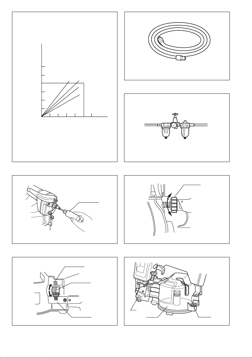
• Make sure that the pressure supplied by the com-
pressed air system does not exceed the maximum
allowable pressure of the fastener driving tool. Set
the air pressure initially to the lower value of the
recommended allowable pressure (see SPECIFICA-
TIONS).
• Never use the tool with other than compressed air.
If bottled gas (carbon dioxide, oxygen, nitrogen,
hydrogen, air, etc.) or combustible gas (hydrogen,
propane, acetylene, etc.) is used as a power source
for this tool, the tool will explode and cause serious
injury.
• Always check the tool for its overall condition and
loose screws before operation. Tighten as
required.
• Make sure all safety systems are in working order
before operation. The tool must not operate if only
the trigger is pulled or if only the contact arm is
pressed against the wood. It must work only when
both actions are performed. Test for possible faulty
operation with nails unloaded and the pusher in
fully pulled position.
• Make sure that the trigger is locked when the
change lever is set to the LOCK position.
• Check walls, ceilings, floors, roofing and the like
carefully to avoid possible electrical shock, gas
leakage, explosions, etc. caused by striking live
wires, conduits or gas pipes.
• Use only nails specified in this manual. The use of
any other nails may cause malfunction of the tool.
• Never use fastener driving tools marked
with the symbol “Do not use on scaf-
foldings, ladders” for specific applica-
tion for example:
- when changing one driving location to another
involves the use of scaffoldings, stairs, ladders,
or ladder alike constructions, e.g. roof laths;
- closing boxes or crates;
- fitting transportation safety systems e.g. on vehi-
cles and wagons.
• Do not permit those uninstructed to use the tool.
• Make sure no one is nearby before nailing. Never
attempt to nail from both the inside and outside at
the same time. Nails may rip through and/or fly off,
presenting a grave danger.
• Watch your footing and maintain your balance with
the tool. Make sure there is no one below when
working in high locations, and secure the air hose
to prevent danger if there is sudden jerking or
catching.
• On rooftops and other high locations, nail as you
move forward. It is easy to lose your footing if you
nail while inching backward. When nailing against
perpendicular surface, nail from the top to the bot-
tom. You can perform nailing operations with less
fatigue by doing so.
• A nail will be bent or the tool can become jammed if
you mistakenly nail on top of another nail or strike
a knot in the wood. The nail may be thrown and hit
someone, or the tool itself can react dangerously.
Place the nails with care.
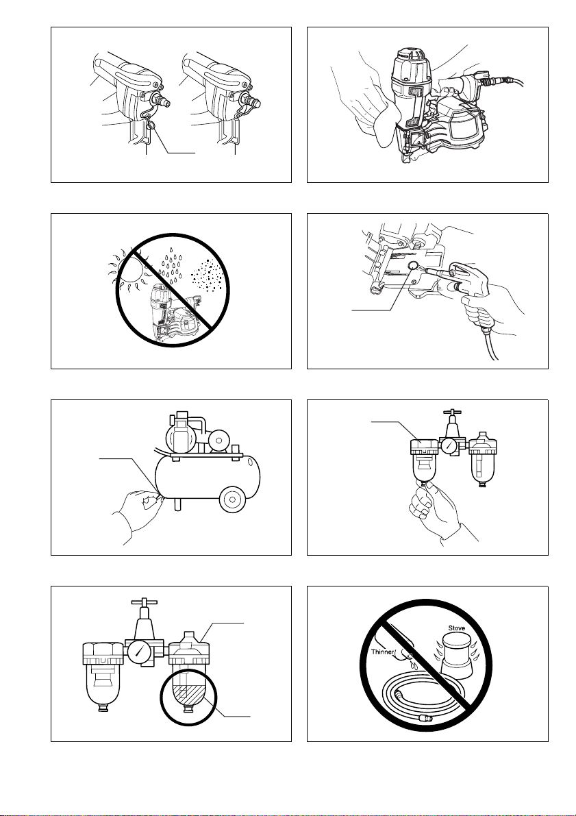
• Do not leave the loaded tool or the air compressor
under pressure for a long time out in the sun. Be
sure that dust, sand, chips and foreign matter will
not enter the tool in the place where you leave it
setting.
• Do not point the ejection port at anyone in the
vicinity. Keep hands and feet away from the ejec-
tion port area.
• When the air hose is connected, do not carry the
tool with your finger on the trigger or hand it to
someone in this condition. Accidental firing can be
extremely dangerous.
• Handle the tool carefully, as there is high pressure
inside the tool that can be dangerous if a crack is
caused by rough handling (dropping or striking).
Do not attempt to carve or engrave on the tool.
• Stop nailing operations immediately if you notice
something wrong or out of the ordinary with the
tool.
• Always disconnect the air hose and remove all of
the nails:
1. When unattended.
2. Before performing any maintenance or repair.
3. Before cleaning a jam.
4. Before moving the tool to a new location.
• Perform cleaning and maintenance right after fin-
ishing the job. Keep the tool in tip-top condition.
Lubricate moving parts to prevent rusting and min-
imize friction-related wear. Wipe off all dust from
the parts.
• When not operating the tool, always lock the trig-
ger by turning the change lever to the LOCK posi-
tion.
• Do not modify tool without authorization from
Makita.
• Ask Makita’s Authorized service centers for period-
ical inspection of the tool.
• To maintain product SAFETY and RELIABILITY,
maintenance and repairs should be performed by
Makita Authorized Service Centers, always using
Makita replacement parts.
• Use only pneumatic tool oil specified in this man-
ual.
• Never connect tool to compressed air line where
the maximum allowable pressure of tool cannot be
exceeded by 10%. Make sure that the pressure sup-
plied by the compressed air system does not
exceed the maximum allowable pressure of the fas-
tener driving tool. Set the air pressure initially to
the lower value of the recommended allowable
pressure.
• Do not attempt to keep the trigger or contact ele-
ment depressed with tape or wire. Death or serious
injury may occur.
• Always check contact element as instructed in this
manual. Nails may be driven accidentally if the
safety mechanism is not working correctly.
SAVE THESE INSTRUCTIONS.

9
INSTALLATION
Selecting compressor (Fig. 1)
The air compressor must comply with the requirements
of EN60335-2-34.
Select a compressor that has ample pressure and air
output to assure cost-efficient operation. The graph
shows the relation between nailing frequency, applicable
pressure and compressor air output.
Thus, for example, if nailing takes place at a rate of
approximately 50 times per minute at a compression of
0.59 MPa (5.9 bar), a compressor with an air output over
80 liters/minute is required.
Pressure regulators must be used to limit air pressure to
the rated pressure of the tool where air supply pressure
exceeds the tool’s rated pressure. Failure to do so may
result in serious injury to tool operator or persons in the
vicinity.
Selecting air hose (Fig. 2)
Use an air hose as large and as short as possible to
assure continuous, efficient nailing operation. With an air
pressure of 0.49 MPa (4.9 bar), an air hose with an inter-
nal diameter of over 6.5 mm and a length of less than
20 m is recommended when the interval between each
nailing is 0.5 seconds.
CAUTION:
• Low air output of the compressor, or a long or smaller
diameter air hose in relation to the nailing frequency
may cause a decrease in the driving capability of the
tool.
Lubrication
To insure maximum performance, install an air set (oiler,
regulator, air filter) as close as possible to the tool. Adjust
the oiler so that one drop of oil will be provided for every
30 nails. (Fig. 3)
When an air set is not used, oil the tool with pneumatic
tool oil by placing 2 (two) or 3 (three) drops into the air fit-
ting. This should be done before and after use. For
proper lubrication, the tool must be fired a couple of
times after pneumatic tool oil is introduced. (Fig. 4)
FUNCTIONAL DESCRIPTION
CAUTION:
• Always lock the trigger and disconnect the hose before
adjusting or checking function on the tool.
Adjusting depth of nailing (Fig. 5)
To adjust the depth of nailing, turn the adjuster so that
the arrow above the adjuster will point to the number indi-
cated on the adjuster. The depth of nailing is the deepest
when the arrow points to the number 1. It will become
shallower as the arrow points to higher number. The
depth can be changed in approx. 1.0 mm increments per
graduation. If nails cannot be driven deep enough even
when the arrow points to the number 1, increase the air
pressure. If nails are driven too deep even when the
arrow points to the number 8, decrease the air pressure.
Generally speaking, the tool service life will be longer
when the tool is used with lower air pressure and the
adjuster set to a lower number.
ASSEMBLY
CAUTION:
• Always lock the trigger and disconnect the hose before
carrying out any work on the tool.
Selecting wire/plastic collated coil (Fig. 6)
According to the type of collated coil, set the change
lever.
Loading nailer
CAUTION:
• Make sure that nails are collated firmly and are not
bent.
Select nails suitable for your work. Depress the latch
lever and open the magazine cap. (Fig. 7)
Lift and turn the coil support plate to set it to the gradua-
tions of the magazine. If the tool is operated with the coil
support plate set to the wrong step, poor nail feed or mal-
function of the tool may result. (Fig. 8)
Place the nail coil over the coil support plate. Uncoil
enough nails to reach the feed claw. Place the first nail in
the driver channel and the second nail in the feed claw.
The nail heads must be in the slot in the feeder body.
Place other uncoiled nails on feeder body and attach
them to the magnet. Be sure that nails are in the feeder
claw and are not bent. Then close the magazine cap.
(Fig. 9)
Connecting air hose (Fig. 10)
Lock the trigger. Slip the air socket of the air hose onto
the air fitting on the nailer. Be sure that the air socket
locks firmly into position when installed onto the air fit-
ting. A hose coupling must be installed on or near the tool
in such a way that the pressure reservoir will discharge at
the time the air supply coupling is disconnected.
OPERATION
CAUTION:
• Make sure all safety systems are in working order
before operation.
1. To drive a nail, you may place the contact element
against the workpiece and pull the trigger,
or
2. Pull the trigger first and then place the contact ele-
ment against the workpiece. (Fig. 11 & 12)
• No. 1 method is for intermittent nailing, when you wish
to drive a nail carefully and very accurately. No. 2
method is for continuous nailing.
Continuous nailing and trigger locking method
(Fig. 13)
For continuous nailing, set the change lever to the “Con-
tinuous Nailing” position. For locking the trigger, set the
change lever to the “Lock” position. Always make sure
that the change lever is properly set to the position.
CAUTION:
• Operating the tool without nails shortens the life of the
tool and should be avoided.
Air exhaust (Fig. 14)
Air exhaust direction can be changed easily by rotating
the exhaust cover. Change it when necessary.

10
Jammed nailer (Fig. 15)
CAUTION:
• Always lock the trigger, disconnect the hose and
remove the nails from the magazine before cleaning a
jam.
When the nailer becomes jammed, do as follows:
Open the door and magazine cap and remove the nail
coil. Insert a small rod or the like into the ejection port
and tap it with a hammer to drive out the nail jamming
from the ejection port. Reset the nail coil and close the
magazine cap and door.
Hook (Fig. 16)
The hook is convenient for hanging the tool temporarily.
This hook can be installed on either side of the tool.
CAUTION:
• Always lock the trigger and disconnect the hose when
hanging the tool using the hook.
• Always tighten the hook securing bolt firmly.
• Never hang the tool on a waist belt or like. Dangerous
accidental firing may result. (Fig. 17)
Nails
Handle nail strips and their box carefully. If the nail coils
have been handled roughly, they may be out of shape or
their connector breaks, causing poor nail feed. (Fig. 18)
Avoid storing nails in a very humid or hot place or place
exposed to direct sunlight. (Fig. 19)
MAINTENANCE
CAUTION:
• Always disconnect the air hose from the tool before
attempting to perform inspection or maintenance.
Maintenance of nailer
Always check the tool for its overall condition and loose
screws before operation. Tighten as required. (Fig. 20)
Make sure all safety systems are in working order before
operation. The tool must not operate if only the trigger is
pulled or if only the contact element is pressed against
the wood. It must work only when both actions are per-
formed. Test for possible faulty operation with nails
unloaded.
Entering dirt or foreign matter into the tool may cause
damage to the tool. (Fig. 21 & 22)
Make sure that the trigger is locked when the change
lever is set to the LOCK position. (Fig. 23)
When not in use, lock the trigger and disconnect the
hose. Then cap the air fitting with the cap. (Fig. 24)
When the tool is not to be used for an extended period of
time, lubricate the tool using pneumatic tool oil and store
the tool in a safe place. Avoid exposure to direct sunlight
and/or humid or hot environment. (Fig. 25 & 26)
Iron dust that adhere to the magnet can be blown off by
using an air duster. (Fig. 27)
Maintenance of compressor, air set and air hose
After operation, always drain the compressor tank and
the air filter. If moisture is allowed to enter the tool, it may
result in poor performance and possible tool failure.
(Fig. 28 & 29)
Check regularly to see if there is sufficient pneumatic oil
in the oiler of the air set. Failure to maintain sufficient
lubrication will cause O-rings to wear quickly. (Fig. 30)
Keep the air hose away from heat (over 60°C, over
140°F), away from chemicals (thinner, strong acids or
alkalis). Also, route the hose away from obstacles which
it may become dangerously caught on during operation.
Hoses must also be directed away from sharp edges and
areas which may lead to damage or abrasion to the hose.
(Fig. 31)
To maintain product SAFETY and RELIABILITY, repairs,
any other maintenance or adjustment should be per-
formed by Makita Authorized Service Centers, always
using Makita replacement parts.
ACCESSORIES
CAUTION:
• These accessories or attachments are recommended
for use with your Makita tool specified in this manual.
The use of any other accessories or attachments might
present a risk of injury to persons. Only use accessory
or attachment for its stated purpose.
If you need any assistance for more details regarding
these accessories, ask your local Makita service center.
• Nails
• Safety goggles
• Air hoses
Other manuals for AN621
5
Table of contents
Other Makita Power Tools manuals

Makita
Makita JN3200 User manual

Makita
Makita Makstar BSS610 User manual

Makita
Makita HM1214C User manual

Makita
Makita AN901 User manual

Makita
Makita HM1800 User manual

Makita
Makita DF330D User manual

Makita
Makita DHK180 User manual

Makita
Makita HM1214C User manual

Makita
Makita BST220 Manual

Makita
Makita DFL650F User manual

Makita
Makita 6911HD User manual

Makita
Makita DHR242ZJ User manual

Makita
Makita DST111 User manual

Makita
Makita 3901 User manual

Makita
Makita 6924N User manual

Makita
Makita SG1251 User manual

Makita
Makita JS8000 User manual

Makita
Makita DJV184 User manual

Makita
Makita 4322 User manual

Makita
Makita BJS160 User manual