10 ENGLISH
WARNING:
The vibration emission during actual
use of the power tool can differ from the declared emission
value depending on the ways in which the tool is used.
WARNING: Be sure to identify safety measures
to protect the operator that are based on an estima-
tion of exposure in the actual conditions of use (taking
account of all parts of the operating cycle such as
the times when the tool is switched off and when it is
running idle in addition to the trigger time).
EC Declaration of Conformity
For European countries only
The EC declaration of conformity is included as Annex A
to this instruction manual.
General Power Tool Safety Warnings
WARNING
Read all safety warnings and all instruc-
tions. Failure to follow the warnings and instructions may
result in electric shock, re and/or serious injury.
Save all warnings and instructions for
future reference.
ROUTER SAFETY WARNINGS
1.
Hold power tool by insulated gripping surfaces,
because the cutter may contact its own cord. Cutting
a "live" wire may make exposed metal parts of the
power tool "live" and shock the operator.
2.
Use clamps or another practical way to secure and
support the workpiece to a stable platform. Holding
the work by your hand or against the body leaves it
unstable and may lead to loss of control.
3. Wear hearing protection during extended
period of operation.
4. Handle the bits very carefully.
5. Check the bit carefully for cracks or damage
before operation. Replace cracked or damaged
bit immediately.
6. Avoid cutting nails. Inspect for and remove all
nails from the workpiece before operation.
7. Hold the tool rmly with both hands.
8. Keep hands away from rotating parts.
9. Make sure the bit is not contacting the work-
piece before the switch is turned on.
10.
Before using the tool on an actual workpiece, let it
run for a while. Watch for vibration or wobbling that
could indicate improperly installed bit.
11. Be careful of the bit rotating direction and the
feed direction.
12. Do not leave the tool running. Operate the tool
only when hand-held.
13. Always switch off and wait for the bit to come
to a complete stop before removing the tool
from workpiece.
14.
Do not touch the bit immediately after operation; it
may be extremely hot and could burn your skin.
15. Do not smear the tool base carelessly with
thinner, gasoline, oil or the like. They may
cause cracks in the tool base.
16. Draw attention to the need to use cutters of the
correct shank diameter and which are suitable
for the speed of the tool.
17.
Some material contains chemicals which may be
toxic. Take caution to prevent dust inhalation and
skin contact. Follow material supplier safety data.
18.
Always use the correct dust mask/respirator for the
material and application you are working with.
SAVE THESE INSTRUCTIONS.
WARNING:
DO NOT let comfort or familiarity
with product (gained from repeated use) replace
strict adherence to safety rules for the subject
product. MISUSE or failure to follow the safety
rules stated in this instruction manual may
cause serious personal injury.
FUNCTIONAL
DESCRIPTION
CAUTION:
• Always be sure that the tool is switched off and
unplugged before adjusting or checking function
on the tool.
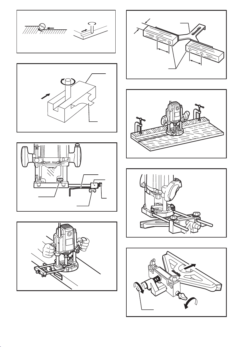
Adjusting the depth of cut
► Fig.1: 1. Adjusting knob 2. Lock lever 3. Stopper
pole setting nut 4. Fast-feed button
5. Adjusting bolt 6. Stopper block 7. Depth
pointer 8. Stopper pole
Place the tool on a at surface. Loosen the lock lever and
lower the tool body until the bit just touches the at surface.
Tighten the lock lever to lock the tool body.
Turn the stopper pole setting nut counterclockwise. Lower
the stopper pole until it makes contact with the adjusting bolt.
Align the depth pointer with the "0" graduation. The depth of
cut is indicated on the scale by the depth pointer.
While pressing the fast-feed button, raise the stopper
pole until the desired depth of cut is obtained. Minute
depth adjustments can be obtained by turning the
adjusting knob (1 mm per turn).
By turning the stopper pole setting nut clockwise, you
can fasten the stopper pole rmly.
Now, your predetermined depth of cut can be obtained
by loosening the lock lever and then lowering the tool
body until the stopper pole makes contact with the
adjusting hex bolt of the stopper block.
Nylon nut
► Fig.2: 1. Nylon nut
The upper limit of the tool body can be adjusted by
turning the nylon nut.
CAUTION:
• Do not lower the nylon nut too low. The bit will
protrude dangerously.