Makita BJN160 User manual

1
GB Cordless Nibbler INSTRUCTION MANUAL
SBatteridriven nibblingsmaskin BRUKSANVISNING
NTrådløs nibbler BRUKSANVISNING
FIN Akkukäyttöinen nakertaja KÄYTTÖOHJE
LV Bezvada izciršanas šķēres LIETOŠANAS INSTRUKCIJA
LT Belaidės skardos žirklės NAUDOJIMO INSTRUKCIJA
EE Juhtmeta lõikur KASUTUSJUHEND
RUS
Аккумуляторные Высечные Ножницы
РУКОВОДСТВО ПО ЭКСПЛУАТАЦИИ
BJN160
BJN161

2
1
2
3
1 013273
1
2 012128
1
23
4
3 013275
1
2
3
4 004775
1
5 013276
1
6 013277
1
2
34
7 004779
1
2
34
5
6
8 013274
1
2
9 004781
1
2
3
4
10 004782 11 013278 12 013279

3
12
13 004791
1
14 001145
12
3
15 013281
1
2
16 013282

4
ENGLISH (Original instructions)
Explanation of general view
1-1. Button
1-2. Red indicator
1-3. Battery cartridge
2-1. Star marking
3-1. Die holder
3-2. Lock nut
3-3. Loosen
3-4. Wrench
4-1. Gauge for cutting stainless:
1.2 mm (3/64")
4-2. Gauge for cutting mild steel:
1.6 mm (1/16")
4-3. Notch
5-1. Slide switch
6-1. Indicating lamp
7-1. Die holder
7-2. Die
7-3. Bolts
7-4. Hex wrench
8-1. Punch
8-2. Punch holder
8-3. Screw
8-4. Hex wrench
8-5. Loosen
8-6. Tighten
9-1. Punch
9-2. Notch
10-1. Bolts
10-2. Die
10-3. Punch
10-4. Die holder
13-1. From the side view
13-2. Cutting head should be at a right
angle (90 ゚) to cutting surface.
14-1. Limit mark
15-1. Holder cap cover
15-2. Notch
15-3. Screwdriver
16-1. Brush holder cap
16-2. Screwdriver
SPECIFICATIONS
Model BJN160 BJN161
Steel up to 400 N/mm21.6 mm / 16 ga 1.6 mm / 16 ga
Steel up to 600 N/mm21.2 mm / 18 ga 1.2 mm / 18 ga
Max. cutting capacities
Aluminum up to 200 N/mm22.5 mm / 12 ga 2.5 mm / 12 ga
Outside edge 50 mm 50 mm
Min. cutting radius Inside edge 45 mm 45 mm
Strokes per minute (min-1) 1,900 1,900
Overall length 313 mm 313 mm
Net weight 2.1 kg 2.2 kg
Rated voltage D.C. 14.4 V D.C. 18 V
• Due to our continuing program of research and development, the specifications herein are subject to change without notice.
• Specifications and battery cartridge may differ from country to country.
• Weight, with battery cartridge, according to EPTA-Procedure 01/2003
ENE037-1
Intended use
The tool is intended for cutting sheet steel and stainless
sheet steel.
ENG905-1
Noise
The typical A-weighted noise level determined
according to EN60745:
Model BJN160
Sound pressure level (LpA) : 72 dB (A)
Uncertainty (K) : 3 dB (A)
The noise level under working may exceed 80 dB (A).
Model BJN161
Sound pressure level (LpA) : 73 dB (A)
Uncertainty (K) : 3 dB (A)
The noise level under working may exceed 80 dB (A).
Wear ear protection
ENG900-1
Vibration
The vibration total value (tri-axial vector sum)
determined according to EN60745:
Model BJN160
Work mode : cutting sheet metal
Vibration emission (ah) : 7.0 m/s2
Uncertainty (K) : 1.5 m/s2
Model BJN161
Work mode : cutting sheet metal
Vibration emission (ah) : 6.5 m/s2
Uncertainty (K) : 1.5 m/s2
ENG901-1
• The declared vibration emission value has been
measured in accordance with the standard test
method and may be used for comparing one tool
with another.
• The declared vibration emission value may also be
used in a preliminary assessment of exposure.

5
WARNING:
• The vibration emission during actual use of the
power tool can differ from the declared emission
value depending on the ways in which the tool is
used.
• Be sure to identify safety measures to protect the
operator that are based on an estimation of
exposure in the actual conditions of use (taking
account of all parts of the operating cycle such as
the times when the tool is switched off and when it
is running idle in addition to the trigger time).
ENH101-16
For European countries only
EC Declaration of Conformity
We Makita Corporation as the responsible
manufacturer declare that the following Makita
machine(s):
Designation of Machine:
Cordless Nibbler
Model No./ Type: BJN160, BJN161
are of series production and
Conforms to the following European Directives:
2006/42/EC
And are manufactured in accordance with the following
standards or standardised documents:
EN60745
The technical documentation is kept by:
Makita International Europe Ltd.
Technical Department,
Michigan Drive, Tongwell,
Milton Keynes, Bucks MK15 8JD, England
26.4.2012
000230
Tomoyasu Kato
Director
Makita Corporation
3-11-8, Sumiyoshi-cho,
Anjo, Aichi, 446-8502, JAPAN
GEA010-1
General Power Tool Safety
Warnings
WARNING Read all safety warnings and all
instructions. Failure to follow the warnings and
instructions may result in electric shock, fire and/or
serious injury.
Save all warnings and instructions for
future reference.
GEB028-2
NIBBLER SAFETY WARNINGS
1. Hold the tool firmly.
2. Secure the workpiece firmly.
3. Keep hands away from moving parts.
4. Edges and chips of the workpiece are sharp.
Wear gloves. It is also recommended that you
put on thickly bottomed shoes to prevent
injury.
5. Do not put the tool on the chips of the
workpiece. Otherwise it can cause damage
and trouble on the tool.
6. Do not leave the tool running. Operate the tool
only when hand-held.
7. Always be sure you have a firm footing.
Be sure no one is below when using the tool
in high locations.
8. Do not touch the punch, die or the workpiece
immediately after operation; they may be
extremely hot and could burn your skin.
9. Avoid cutting electrical wires. It can cause
serious accident by electric shock.
SAVE THESE INSTRUCTIONS.
WARNING:
DO NOT let comfort or familiarity with product
(gained from repeated use) replace strict adherence
to safety rules for the subject product. MISUSE or
failure to follow the safety rules stated in this
instruction manual may cause serious personal
injury.
ENC007-8
IMPORTANT SAFETY
INSTRUCTIONS
FOR BATTERY CARTRIDGE
1. Before using battery cartridge, read all
instructions and cautionary markings on (1)
battery charger, (2) battery, and (3) product
using battery.
2. Do not disassemble battery cartridge.
3. If operating time has become excessively
shorter, stop operating immediately. It may
result in a risk of overheating, possible burns
and even an explosion.
4. If electrolyte gets into your eyes, rinse them
out with clear water and seek medical
attention right away. It may result in loss of
your eyesight.
5. Do not short the battery cartridge:
(1) Do not touch the terminals with any
conductive material.
(2) Avoid storing battery cartridge in a
container with other metal objects such
as nails, coins, etc.

6
(3) Do not expose battery cartridge to water
or rain.
A battery short can cause a large current flow,
overheating, possible burns and even a
breakdown.
6. Do not store the tool and battery cartridge in
locations where the temperature may reach or
exceed 50 ゚C (122 ゚F).
7. Do not incinerate the battery cartridge even if
it is severely damaged or is completely worn
out. The battery cartridge can explode in a fire.
8. Be careful not to drop or strike battery.
9. Do not use a damaged battery.
10. Follow your local regulations relating to
disposal of battery.
SAVE THESE INSTRUCTIONS.
Tips for maintaining maximum battery life
1. Charge the battery cartridge before
completely discharged.
Always stop tool operation and charge the
battery cartridge when you notice less tool
power.
2. Never recharge a fully charged battery
cartridge.
Overcharging shortens the battery service life.
3. Charge the battery cartridge with room
temperature at 10 ゚C - 40 ゚C (50 ゚F - 104 ゚F).
Let a hot battery cartridge cool down before
charging it.
4. Charge the battery cartridge once in every six
months if you do not use it for a long period
of time.
FUNCTIONAL DESCRIPTION
CAUTION:
• Always be sure that the tool is switched off and the
battery cartridge is removed before adjusting or
checking function on the tool.
Installing or removing battery cartridge
Fig.1
CAUTION:
• Always switch off the tool before installing or
removing of the battery cartridge.
• Hold the tool and the battery cartridge firmly
when installing or removing battery cartridge.
Failure to hold the tool and the battery cartridge
firmly may cause them to slip off your hands and
result in damage to the tool and battery cartridge
and a personal injury.
To remove the battery cartridge, slide it from the tool
while sliding the button on the front of the cartridge.
To install the battery cartridge, align the tongue on the
battery cartridge with the groove in the housing and slip
it into place. Insert it all the way until it locks in place
with a little click. If you can see the red indicator on the
upper side of the button, it is not locked completely.
CAUTION:
• Always install the battery cartridge fully until the
red indicator cannot be seen. If not, it may
accidentally fall out of the tool, causing injury to
you or someone around you.
• Do not install the battery cartridge forcibly. If the
cartridge does not slide in easily, it is not being
inserted correctly.
Battery protection system
The tool is equipped with a battery protection system.
This system automatically cuts off power to the motor to
extend battery life.
The tool will automatically stop during operation if the
tool and/or battery are placed under one of the following
conditions:
• Overloaded:
The tool is operated in a manner that causes
it to draw an abnormally high current.
In this situation, turn the tool off and stop the
application that caused the tool to become
overloaded. Then turn the tool on to restart.
If the tool does not start, the battery is
overheated. In this situation, let the battery
cool before turning the tool on again.
• Low battery voltage:
The remaining battery capacity is too low
and the tool will not operate. In this situation,
remove and recharge the battery.

7
NOTE:
The overheat protection works only with a battery
cartridge with a star mark.
Fig.2
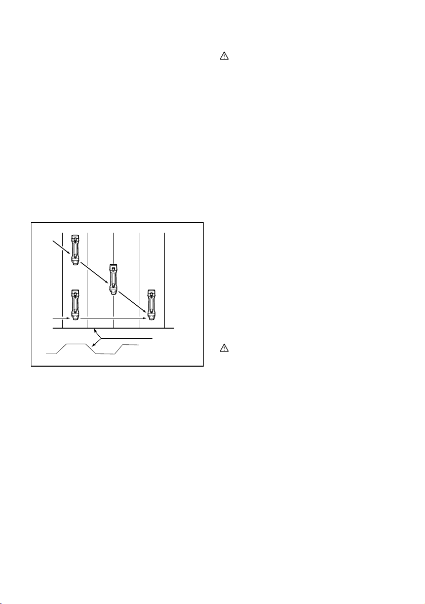
Changing the die position
Fig.3
The die holder position can be changed 360°. To
change it, proceed as follows.
1. Loosen the lock nut with the wrench provided.
2. Pull the die holder slightly and turn it to the
desired position for operation.
3. Tighten the lock nut to secure the die holder in
the desired position.
There are four positive stops at 90° each: 0°, 90° left
and right and 180°. To position the die to any of these
positive stops:
4. Loosen the lock nut with the wrench provided.
5. Pull the die holder slightly and depress lightly
while turning it to the desired position. The die
holder will lock into one of the positive stop
positions as desired.
6. Turn the die holder slightly to make sure that it is
positively locked into position.
7. Tighten the lock nut to secure the die holder.
Permissible cutting thickness
Fig.4
The thickness of material to be cut depends upon the
tensile strength of the material itself. The groove on the
die holder acts as a thickness gauge for allowable
cutting thickness. Do not attempt to cut any material
which will not fit into this groove.
Cutting line
The notch in the die holder indicates your cutting line.
Its width is equal to the cutting width. Align the notch to
the cutting line on the workpiece when cutting.
Switch action
Fig.5
CAUTION:
• Before inserting the battery cartridge into the tool,
always check to see that the slide switch actuates
properly and returns to the "OFF" position when
the rear of the slide switch is depressed.
• Switch can be locked in "ON" position for ease of
operator comfort during extended use. Apply
caution when locking tool in "ON" position and
maintain firm grasp on tool.
To start the tool, slide the slide switch toward the "I
(ON)" position. For continuous operation, press the front
of the slide switch to lock it.
To stop the tool, press the rear of the slide switch, then
slide it toward the "O (OFF)" position.
Indication lamp with multi function
Fig.6
Indication lamps are located in two positions.
−Battery cartridge replacing signal
−When the battery power is almost used up
during operation, the red lamp lights up and
the tool stops immediately. Replace the
battery with fully charged one when the red
lamp lights up.
−Accidental re-start preventive function
−Even if the battery cartridge is inserted on
the tool with the slide switch in the "I (ON)"
position, the tool does not start. At this time,
the lamp flickers slowly and this shows that
the accidental re-start preventive function is
at work.
−To start the tool, first slide the slide switch
toward the "O (OFF)" position and then slide
it toward the "I (ON)" position.
ASSEMBLY
CAUTION:
• Always be sure that the tool is switched off and the
battery cartridge is removed before carrying out
any work on the tool.
Removing or installing the punch and die
Fig.7
Always replace the punch and die as a set. To remove
the punch and die, loosen the lock nut with the wrench.
Remove the die holder from the tool. Use the hex
wrench to loosen the bolts which secure the die.
Remove the die from the die holder.
Use the hex wrench to loosen the screw which secures
the punch. Pull the punch out of the punch holder.
Fig.8
To install the punch and die, insert the punch into the
punch holder so that the notch in the punch faces
toward the screw. Tighten the screw to secure the
punch. Install the die on the die holder. Tighten the bolts
to secure the die.
Fig.9
Then install the die holder on the tool so that the punch
is inserted through the hole in the die holder. Tighten the
lock nut to secure the die holder. After replacing the
punch and die, lubricate them with machine oil and run
the tool for a while.
Fig.10

8
OPERATION
Pre-lubrication
Coat the cutting line with machine oil to increase the
punch and die service life. This is particularly important
when cutting aluminum.
Cutting method
Fig.11
Hold the tool so that the cutting head is at a right angle
(90°) to the workpiece being cut. Move the tool gently in
the cutting direction.
Cutouts
Fig.12
Cutouts can be done by first opening a round hole over
21 mm in diameter which the cutting head can be
inserted into.
Cutting the corrugated or trapezoidal sheet
metals
1
2
3
4
5
013280
Set the die position so that the die faces the cutting
direction either when cutting at an angle or
perpendicular go grooves in corrugated or trapezoidal
sheet metals.
Fig.13
Always hold the tool body parallel to the grooves with
the cutting head at a right angle (90°) to the cutting
surface as shown in the figure.
MAINTENANCE
CAUTION:
• Always be sure that the tool is switched off and the
battery cartridge is removed before attempting to
perform inspection or maintenance.
• Never use gasoline, benzine, thinner, alcohol or
the like. Discoloration, deformation or cracks may
result.
Replacing carbon brushes
Fig.14
Remove and check the carbon brushes regularly.
Replace when they wear down to the limit mark. Keep
the carbon brushes clean and free to slip in the holders.
Both carbon brushes should be replaced at the same
time. Use only identical carbon brushes.
Insert the top end of slotted bit screwdriver into the
notch in the tool and remove the holder cap cover by
lifting it up.
Fig.15
Use a screwdriver to remove the brush holder caps.
Take out the worn carbon brushes, insert the new ones
and secure the brush holder caps.
Fig.16
Reinstall the holder cap cover on the tool.
To maintain product SAFETY and RELIABILITY, repairs,
any other maintenance or adjustment should be
performed by Makita Authorized Service Centers,
always using Makita replacement parts.
OPTIONAL ACCESSORIES
CAUTION:
• These accessories or attachments are
recommended for use with your Makita tool
specified in this manual. The use of any other
accessories or attachments might present a risk of
injury to persons. Only use accessory or
attachment for its stated purpose.
If you need any assistance for more details regarding
these accessories, ask your local Makita Service Center.
• Die
• Punch
• Hex wrench
• Wrench 32
• Makita genuine battery and charger
NOTE:
• Some items in the list may be included in the tool
package as standard accessories. They may differ
from country to country.
1. From the top view
2. Cutting at an angle to grooves
3. Cutting perpendicular to grooves
4. From the side view
5. Corrugated or trapezoidal sheet metal
Other manuals for BJN160
7
Table of contents
Other Makita Power Tools manuals

Makita
Makita DHR280 User manual

Makita
Makita HM0860C Manual

Makita
Makita AN450H User manual

Makita
Makita 4350T User manual

Makita
Makita DSC163 User manual

Makita
Makita HM1802 User manual

Makita
Makita DTM40 User manual

Makita
Makita HM1242C User manual

Makita
Makita MRP100 User manual

Makita
Makita JS1670 User manual
Popular Power Tools manuals by other brands

Cannon Tools
Cannon Tools NEILSEN CT2594 Instructions & assembly

Hitachi
Hitachi CE 18DSL instruction manual

Black & Decker
Black & Decker kx1650-qs Original instructions

Silverline
Silverline 124799 Original instructions

Sandrigarden
Sandrigarden SG-FP SNAP LITIO instruction manual

Thomas&Betts
Thomas&Betts Sta-Kon PAIR22-6 operating instructions