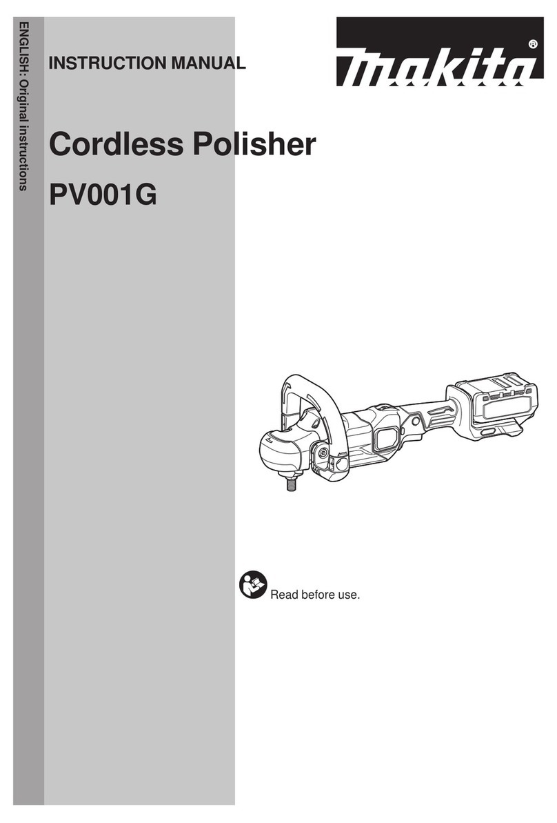
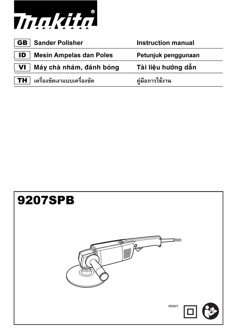
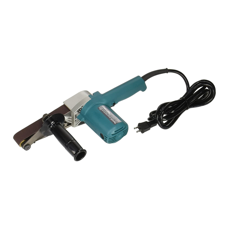
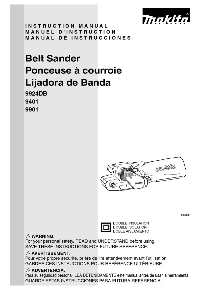
Makita PV7001C User manual

Electronic
Polisher
180
mm
(7")
MODEL
PV7001
C
Noload speed
(RPM)
600
-
2,00O/min
INSTRUCTIONMANUAL
Overall length Net weight Spindlethread
210
mm
(8-1/4")
2
0
kg
(44
Ibs)
518"

GENERAL SAFETY RULES
USAOO1-l
(For
All
Tools)
WARNING! Read and understand all instructions.
Failure
tofollow all instructionslisted below, may result
in
electric
shock, fire and/or serious personal injury.
SAVE
THESE
INSTRUCTIONS
Work Area
1.
Keepyour work area cleanandwell
lit.
Clutteredbenches and dark areas invite
accidents.
2.
Do
notoperate power tools
in
explosiveatmospheres, suchas inthe presence
of flammable liquids, gases,
or
dust. Power tools create sparks which may
ignite the dust or fumes.
3.
Keep bystanders, children, and visitors away while operating a power tool.
Distractions can cause you to lose control.
Electrical Safety
4.
Grounded tools must be plugged into an outlet properly installed and
grounded in accordance with all codes and ordinances. Never remove the
gro'undingprongor modify
the
pluginany way.
Do
notuseany adaptorplugs.
-
Checkwithaqualified electrician ifyou are
in
doubtas towhether the outlet
isproperly grounded. If the tools should electricallymalfunctionor breakdown,
grounding provides
a
low resistance path to carry electricity away from the
user.
5.
Avoid body contact withgroundedsurfacessuch as pipes, radiators, ranges
and refrigerators. There is an increased risk of electric shock if your body is
grounded.
6.
Do
notexpose power tools torainor wet conditions. Water entering
a
power
tool will increase the risk of electric shock.
7.
Do
not abusethe cord. Never usethe cordto carry
the
tools or pullthe plug
from an outlet. Keepcord awayfrom heat, oil, sharpedges or movingparts.
Replace damaged cords immediately. Damaged cords increase the risk of
electric shock.
8.
Whenoperatinga power tooloutside, useanoutdoor extensioncordmarked
"W-A'
or "W." These cords are rated for outdoor use and reduce the risk
of electric shock.
Personal Safety
9.
Stay alert, watchwhat you are doingandusecommon sense when operating
a power tool.
Do
not use tool while tired or under the influence of drugs,
alcohol, or medication.
A
moment of inattention while operatingpower tools
may result in serious personal injury.
2

IO.
Dressproperly.
Do
notwear looseclothingorjewelry. Containlonghair. Keep
your hair, clothing, andgloves away from movingparts. Looseclothes, jewelry
or long hair can be caught
in
moving parts.
11.
Avoid accidental starting. Be sure switch is off before plugging
in.
Carrying
tools
with
your finger onthe switchor
plugging
in
tools that havetheswitch
on invites accidents.
12.
Remove adjusting keys or wrenches before turning the tool on. A wrench
or a key that is left attached to a rotating part of the tool may result
in
per-
sonal injury.
13.
Do
notoverreach. Keepproper footing andbalance at alltimes. Proper footing
and balance enables better control of the tool
in
unexpected situations.
14.
Use safety equipment. Always wear eye protection. Dust mask, non-skid
safety shoes, hard hat, or hearing protection must be used for appropriate
conditions.
Tool
Use and Care
15.
Use clamps or other practicalway to secure and support the workpiece to
a stable platform. Holdingthe work by handor against your body is unstable
and may lead to
loss
of control.
16.
Do notforce tool. Use the correct tool for your application. The correct tool
will
do the job better and safer at the rate for which
it
is designed.
17.
Do
not use tool
if
switch does not turn
it
on or off. Any tool that cannot
be controlled
with
the switch is dangerous and must be repaired.
18.
Disconnectthe
plug
fromthe powersource beforemakingany adjustments,
changing accessories, or storingthetool. Such preventive safety measures
reduce the risk of starting the tool accidentally.
19.
Store idle tools out of reach of children and other untrainedpersons.
Tools
are dangerous
in
the hands of untrained users.
20.
Maintain tools
with
care. Keep cutting tools sharp and clean. Properly
maintained tools,
with
sharp cutting edges are less likely tobindand are easier
to control.
21.
Check for misalignment or bindingof moving parts, breakage of parts, and
any other condition that may affect the tools operation.
If
damaged, have
the tool serviced before using. Many accidents are caused
by
poorly main-
tained tools.
22.
Use only accessories that are recommended by the manufacturer for your
model. Accessories that maybe suitablefor onetool, may becomehazardous
when used on another tool.
Service
23.
Tool
service must be performed only by qualified repair personnel. Service
or maintenance performed by unqualified personnel could result
in
a risk of
injury.
24.
When servicingatool, use only identicalreplacementparts. Follow instruc-
tions
in
the Maintenance section of this manual. Use of unauthorized parts
or failure tofollow Maintenance Instructionsmaycreate a risk
of
electric shock
or injury.
3

Specific Safety
Rules
USBO48-1
1.
Accessories must be ratedfor at least the speed recommendedonthe tool
warning label. Wheels and other accessories running over rated speed can
fly apart and cause injury.
2.
Holdtoolby insulated gripping surfaces when performinganoperation where
the cutting tool may contact hidden wiring or its own cord. Contact
with
a
"live" wire
will
make exposed metal parts
of
thetool "live"
and
shock the
operator.
3.
Check the backing pad carefully for cracks, damage or deformity before
operation. Replace cracked, damaged or deformed pad immediately.
4.
Hold the tool firmly.
5.
Keep hands away from rotating parts.
6.
Makesure the abrasive disc or woolbonnet is notcontactingthe workpiece
before the switch is turned on.
7.
When sanding metalsurfaces, watchout for flying sparks. Holdthetool
so
that sparks fly away from you and other persons
or
flammable materials.
8.
Do
not leave the tool running. Operate the tool only when hand-held.
9.
Do
nottouchthe workpiece immediately after operation;
it
may beextremely
hot and could burn your skin.
IO.
Check that the workpiece is properly supported.
1
1.
Paytattentionthat the wheel continues to rotateafter the toolisswitchedoff.
12:
This toolhas not been waterproofed,
so
do notuse water onthe workpiece
13.
Ventilate your work area adequately when you performsanding operations.
surface.
SAVE THESE INSTRUCTIONS.
4

SYMBOLS
The followings show the symbols
used
for tool.
v
....................................
volts
A
....................................
amperes
Hz
....................................
herts
?J
....................................
alternatingcurrent
t'b
....................................
no load speed
.../
min
...................................
revolutionsor reciprocationper minute
5

FUNCTIONAL DESCRIPTION
Switch action
CAUTION:
Beforeplugginginthe tool, alwayscheck to see that the switchtrigger actuatesproperly
andreturns to the
"OFF"
positionwhen released.
To
start the tool, simply pull the trigger.
Releasethe trigger to stop. For continuous
operation, pullthe trigger and then push in
the lock button.
To
stop the tool from the
locked position, pull the trigger fully, then
release
it.
Switch
tri-
Speed adjusting dial
The rotatingspeedcan bechanged by turning the speedadjustingdialto
a
givennumber
setting from
1
to
5.
Higher speed is obtainedwhen the dial is turned inthedirection of number
5.
And lower speed isobtainedwhen
it
isturned inthedirection of number
1.
Referto the tablebelowfor therelationshipbetweenthe number settings on the dialand
theapproximaterotatingspeed.
Number
4
RPM
(min)
600
1
800
1
1300
1
1800
1
2000
CAUTION
:
The speedadjustingdial can beturned only as far as
5
and back to
1.
Do
not force
it
past
5
or
1,
or the speed adjustingfunction may no longer work.
The tool equippedwith electronic function is easy to operate becauseof the following
features.
Electronic speedcontrol for obtainingconstant speed
Possibleto get fine finish, becausethe rotating speedis kept constantly even under the
loadedcondition.
Soft start feature
Safety and soft start becauseof suppressedstartingshock.
6

High-Low speed setting button
The rotatingspeed can be changed instant-
ly
while the tool is running.
Depress the
"I"
position for lowest speed
and depress the
"11"
position for
a
given
number setting.
The rotating speed cannot be changed
when the button is in
"I"
position, even
if
you turn the speed adjusting dial. When
you turn the speed adjusting dial, always
be sure that the button is depressed in
"11"
position.
ASSEMBLY
Installing side grip (auxiliary handle)
81
cover
CAUTION:
@Alwaysbe sure that the tool is switchedoff and unpluggedbefore installingor removing
Always be sure that the side grip is installedsecurely.
Installthe cover, then screw the side grip on the tool securely. The side grip and the cover
can be installedon either side of the tool.
the side grip and the cover.
II
I.
Installing or removing pad
CAUTION:
Always be sure that the tool
is
switched off and unpluggedbefore installingor removing
the pad.
Holdthe spindle with the wrench
so
that it
cannot revolve. Then screw the pad onto
the spindle all the way.
(Thepadcan be usedto installthe optional
sponge pad.)
To remove the pad, follow the installation
procedureinreverse.
7

Installingor removing sponge pad
CAUTION:
Always be sure that the tool is switched off and unpluggedbefore installingor removing
the sponge pad.
Remove
all
dirt
or
foreign matter from the
pad. Install the sponge pad to the pad.
To
remove the pad, pull off it from the pad
slowly.
Installing
or
removing
wool
bonnet
CAUTION:
Always be sure that the tool is switched off and unpluggedbefore installingor removing
the wool bonnet.
Mount the rubber pad onto the spindle.
Screw the lock nut onto the spindle.
I
I
To
tighten the lock nut, hold the spindle
with the wrench
so
that
it
cannot revolve,
then use the lock nut wrench and securely
tighten clockwise.
I
I
Lock nutwrench
8

Fit the wool bonnet completely over the
rubber pad and pull the string tight.
Tie
a
bow knot and tuck the knot and any loose
strings between the wool bonnet and the
rubber pad.
To
removethe wool bonnet,follow the installationurocedure in reverse.
Installingor removing abrasive
disc
CAUTION:
Always be sure that the tool is switched
off
and unpluggedbefore installing
or
removing
the abrasivedisc.
Mountthe rubber padonto the spindle.
screw the
lock
nut onto the spindle.
Fit
the abrasive disc on over the pad and
,$gl
Lock nut
Abrasive
dis
Rubber
pad
Hold
the spindle with the wrench
so
that
it
cannot revolve, then use the lock nut
Lock nut wrench
wrench andsecurely tighten clockwise.
To
removethe lock nut, follow the installa-
tion procedure in reverse.
9

OPERATION
Polishing operationby sponge pad
CAUTION:
Alwayswear safetyglasses or
a
face shieldduringoperation.
In general, keep the sponge pad
at
an
angle
of
about
15"
to the workpiece sur-
face.
CAUTION:
The sponge padmust be usedonly.
Polishingoperationby
wool
bonnet
CAUTION:
Alwayswear safetyglasses or
a
face shield
In general, keep the wool bonnet
at
an
angle of about
15"
to the workpiece sur-
face.
CAUTION:
Excessive pressure
will
result in poor per-
formance and prematurewear to the
wool
bonnet.
duringoperation.
Sanding operation
CAUTION:
Alwayswear safetyglasses or
a
face shieldduringoperation
In general, keep the abrasive disc at an
angle
of
about
15"
to the workpiece sur-
face.
Apply slight pressureonly. Excessivepres-
sure will result in poor performance and
prematurewear to the abrasivedisc.
CAUTION:
Never run the tool without the abrasive
disc.
You mayseriously damage the pad.
10

MAINTENANCE
CAUTIO
N
:
Always be sure that the tool is switched off and unpluggedbeforeattempting to perform
inspectionor maintenance.
Replacingcarbon brushes
Remove and check the carbon brushes
regularly.Replacewhen they wear down to
the limit mark. Keep the carbon brushes
clean and free to slip in the holders. Both
carbon brushes should be replaced at the
same time. Use only identical carbon
brushes.
Use
a
screwdriver to remove the brush
holder caps. Take out the worn carbon
brushes, insert the new ones and secure
the brushholdercaps.
7
Brush
holder
cap
To
maintain productSAFETY and RELIABILITY,repairs, maintenanceor adjustmentshould
be performed by Makita Authorized or Factory Service Centers, always using Makita
replacementparts.
11

ACCESSORIES
CAUTION:
These accessoriesor attachments are recommendedfor use with your Makita tool specified in this
manual. The use of any other accessories or attachments might present a risk of injuryto persons.
The accessoriesor attachments should
be
usedonly inthe properand intendedmanner.
Rubberpad Lock nut
Sponge pad
Wool
bonnet
Abrasive disc
Lock nutwrench
Wrench
12

WARNING
Some dust created by power sanding, sawing, grinding, drilling, and other
constructionactivities containschemicals known
[to
the State of Califomia]
to
cause cancer, birth defects
or
other reproductive harm. Some examples of
these chemicalsare:
0
Crystallinesilicafrom bricks and cement and other masonry products, and
0
Arsenic and chromiumfrom chemically-treatedlumber.
Your risk from these exposures varies, depending on how often you do this
type
of
work.
To
reduce your exposure
to
these chemicals: work in a well
ventilated area, and work with approved safety equipment, such as those
dust masksthat are specially designed
to
filter out microscopicparticles.
Leadfrom lead-based paints,
I
t
MAKITA
LIMITED
ONE YEARWARRANTY
I
Warranty
Policy
Every Makita tool
is
thorou ly inspected and tested before leaving the factory.
It
is warranted
to
be free of defects from workanshl and materials for the period of ONE YEAR from thedate
of
original purchase. Should any troubt develop during this one-year period, return the COMPLETE
tool, freight prepaid,
to
one
of
Makita's Factory or Authorized Service Centers. If inspection shows
the trouble is caused by defective workmanship or material. Makita
will
repair (or at
our
option,
replace) without charge.
This Warranty does not apply where:
repairs have been made or attempted by others:
repairs are required because
of
normal wear
and
tear:
0
The
tool
has been abused, misused
or
improperly maintained;
0
alterationshave been made tothe tool.
IN NO EVENT SHALL MAKITA BE LIABLE
FOR
ANY INDIRECT, INCIDENTAL
OR
CON-
SEQUENTIAL DAMAGES FROM THE SALE
OR
USE OFTHE PRODUCT. THIS DISCLAIMER
APPLIES BOTH DURING AND AFTER THETERM
OF
THISWARRANTY.
MAKITA DISCLAIMS LIABILITY FOR ANY IMPLIED WARRANTIES, INCLUDING IMPLIED
WARRANTIES OF "MERCHANTABILITY"
AND
"FITNESS FOR A SPECIFIC PURPOSE,"
AFTER THEONE-YEAR TERM
OF
THISWARRANTY.
This Warranty gives you specific legal rights, and you may also have other rights which vary from
state to state. Some states do not allow the exclusion or limitation of incidental or consequential
damages,
so
the above limitation or exclusion may not apply to you. Some states do
not
allow
limitation
on
how
long
an implied warranty lasts,
so
the above limitation may not apply
to
you.
t
-
Makita Corporation
3-11
-8,
Sumiyoshi-cho,
Anjo, Aichi
446-8502
Japan
884355-061
PRINTED IN JAPAN
2001-4N
Other manuals for PV7001C
2
Table of contents
Other Makita Sander manuals

Makita
Makita MBO450 User manual

Makita
Makita BO4900V User manual

Makita
Makita BO5040 User manual

Makita
Makita BO6030 User manual

Makita
Makita 9403 User manual

Makita
Makita PW5001C User manual

Makita
Makita PV7001C User manual

Makita
Makita BO4900 User manual

Makita
Makita XSB01 User manual

Makita
Makita DPO500 User manual

Makita
Makita M9204 User manual

Makita
Makita BO6040 User manual

Makita
Makita 9046 User manual

Makita
Makita DBO380 User manual

Makita
Makita 9227CY User manual

Makita
Makita BO4565 User manual

Makita
Makita 9207SPB User manual

Makita
Makita BO3710 User manual

Makita
Makita GV7000 User manual

Makita
Makita 9401 User manual