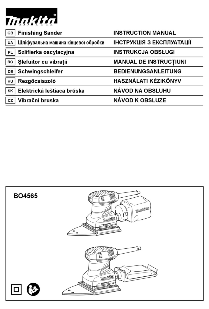
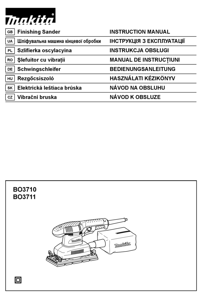
Makita BO3710 User manual

BO3710
BO3711
EN Finishing Sander INSTRUCTION MANUAL 4
SV Osc. planslipmaskin BRUKSANVISNING 7
NO Slipemaskin for nsliping BRUKSANVISNING 10
FI Viimeistely hiomakone KÄYTTÖOHJE 13
LV Apdares slīpmašīna LIETOŠANAS INSTRUKCIJA 16
LT Šlifuotuvas NAUDOJIMO INSTRUKCIJA 19
ET Taldlihvija KASUTUSJUHEND 22
RU Вибрационная
шлифмашина
РУКОВОДСТВО ПО
ЭКСПЛУАТАЦИИ 25

1
2
1
11
22
1
2
1
2
1
2
1
12
Fig.1
Fig.2
Fig.3
Fig.4
Fig.5
Fig.6
Fig.7
Fig.8
2

1
1
2
12
Fig.9
Fig.10
Fig.11
Fig.12
Fig.13
3

4ENGLISH
ENGLISH (Original instructions)
SPECIFICATIONS
Model BO3710 BO3711
Pad size 93 mm x 185 mm
Abrasive paper size 93 mm x 228 mm
Orbits per minute (min-1)11,000 4,000 - 11,000
Overall length 253 mm
Net weight 1.6 kg
Safety class /II
• Duetoourcontinuingprogramofresearchanddevelopment,thespecicationshereinaresubjecttochange
without notice.
• Specicationsmaydifferfromcountrytocountry.
• WeightaccordingtoEPTA-Procedure01/2014
Intended use
Thetoolisintendedforthesandingoflargesurfaceof
wood, plastic and metal materials as well as painted
surfaces.
Power supply
Thetoolshouldbeconnectedonlytoapowersupply
of the same voltage as indicated on the nameplate,
and can only be operated on single-phase AC supply.
Theyaredouble-insulatedinaccordancewithEuropean
Standard and can, therefore, also be used from sockets
without earth wire.
Noise
ThetypicalA-weightednoiseleveldeterminedaccord-
ingtoEN62841:
Sound pressure level (LpA):72dB(A)
Uncertainty(K):3dB(A)
Thenoiselevelunderworkingmayexceed80dB(A).
Wear ear protection
Vibration
Thevibrationtotalvalue(tri-axialvectorsum)deter-
minedaccordingtoEN62841:
Workmode:sandingmetalplate
Vibration emission (ah):3.5m/s2
Uncertainty(K):1.5m/s2
NOTE:
Thedeclaredvibrationemissionvaluehasbeen
measured in accordance with the standard test method
and may be used for comparing one tool with another.
NOTE:
Thedeclaredvibrationemissionvaluemay
also be used in a preliminary assessment of exposure.
WARNING:Thevibrationemissionduringactual
use of the power tool can differ from the declared
emission value depending on the ways in which the
tool is used.
WARNING: Be sure to identify safety measures
to protect the operator that are based on an estima-
tion of exposure in the actual conditions of use (taking
account of all parts of the operating cycle such as
the times when the tool is switched off and when it is
running idle in addition to the trigger time).
EC Declaration of Conformity
For European countries only
TheECdeclarationofconformityisincludedasAnnexA
to this instruction manual.
General power tool safety warnings
WARNING: Read all safety warnings, instruc-
tions, illustrations and specications provided
with this power tool. Failure to follow all instructions
listedbelowmayresultinelectricshock,reand/or
seriousinjury.
Save all warnings and instruc-
tions for future reference.
Theterm"powertool"inthewarningsreferstoyour
mains-operated (corded) power tool or battery-operated
(cordless) power tool.
SANDER SAFETY WARNINGS
1.
Always use safety glasses or goggles. Ordinary
eye or sun glasses are NOT safety glasses.
2. Hold the tool rmly.
3. Do not leave the tool running. Operate the tool
only when hand-held.
4. This tool has not been waterproofed, so do not
use water on the workpiece surface.
5. Ventilate your work area adequately when you
perform sanding operations.
6.
Some material contains chemicals which may be
toxic. Take caution to prevent dust inhalation and
skin contact. Follow material supplier safety data.
7.
Use of this tool to sand some products, paints and
wood could expose user to dust containing hazardous
substances. Use appropriate respiratory protection.
8. Be sure that there are no cracks or breakage
on the pad before use. Cracks or breakage
may cause a personal injury.
SAVE THESE INSTRUCTIONS.

5ENGLISH
WARNING:
DO NOT let comfort or familiar-
ity with product (gained from repeated use)
replace strict adherence to safety rules for
the subject product. MISUSE or failure to fol-
low the safety rules stated in this instruction
manual may cause serious personal injury.
FUNCTIONAL
DESCRIPTION
CAUTION:
• Alwaysbesurethatthetoolisswitchedoffand
unpluggedbeforeadjustingorcheckingfunction
on the tool.
Switch action
►Fig.1: 1. Lock button 2. Switch trigger
CAUTION:
• Beforeplugginginthetool,alwayschecktosee
that the switch trigger actuates properly and
returnstothe"OFF"positionwhenreleased.
Tostartthetool,simplypulltheswitchtrigger.Release
the switch trigger to stop.
For continuous operation, pull the switch trigger and
then push in the lock button.
Tostopthetoolfromthelockedposition,pulltheswitch
trigger fully, then release it.
Speed adjusting dial
For BO3711 only
►Fig.2: 1.Speedadjustingdial
CAUTION:
• Ifthetoolisoperatedcontinuouslyatlow
speeds, the motor will get overloaded and
heated up.
• Thespeedadjustingdialcanbeturnedonlyas
faras5andbackto1.Donotforceitpast5or
1,orthespeedadjustingfunctionmaynolonger
work.
Thetoolspeedcanbeinnitelyadjustedbetween4,000
and 11,000 orbits per minute by turning the speed
adjustingdial,whichismarked1to5.Higherspeedis
obtained when the dial is turned in the direction of num-
ber 5, lower speed is obtained when it is turned in the
directionofnumber1.Adjustthedesiredtoolspeedfor
the kind of work.
ASSEMBLY
CAUTION:
• Alwaysbesurethatthetoolisswitchedoffand
unplugged before carrying out any work on the
tool.
Installing or removing abrasive
paper
For conventional type of abrasive
paper with pre-punched holes
(standard equipment):
►Fig.3
Pressdowntheclamplever(1inthegure)andwith
the clamp lever pressed down slide it toward the tool (2
inthegure)andtheclamperwillbereleased.
Insert the paper end between a clamper and the pad
aligningtheholesinthepaperwiththoseinpad.Then
return the clamp lever to the original position to secure it.
Releasetheotherclampleverbyrepeatingthesameprocedure.
Whilepullingabrasivepapertomaintaintheproper
tension, insert and secure the other end of abrasive
paper between another clamper and the pad and return
the clamp lever to the original position.
Toremovethepaper,releasetheclamperasstatedabove.
For conventional type of abrasive
paper without pre-punched holes
(available on the market):
►Fig.4: 1. Punch plate 2. Abrasive paper without pre-
punched holes
Press down the clamp lever 1 and with the clamp lever
pressed down slide it toward the tool 2 and the clamper
will be released.
Insert the paper end between a clamper and the pad
aligning the paper edges even and parallel with the
sidesofthebase.Thenreturntheclamplevertothe
original position to secure it.
Releasetheotherclampleverbyrepeatingthesameprocedure.
Whilepullingabrasivepapertomaintaintheproper
tension, insert and secure the other end of abrasive
paper between another clamper and the pad and return
the paper clamp lever to the original position.
Place the punch plate (optional accessory) over the
papersothattheguideofthepunchplateisushwith
thesidesofthebase.Thenpressthepunchplateto
make holes in the paper.
Toremovethepaper,releasetheclamperasstatedabove.
For hook-and-loop type of abrasive
paper with pre-punched holes
(optional accessory):
CAUTION:
• Alwaysusehook-and-looptypeofabrasive
papers. Never use pressure-sensitive abrasive
paper.
►Fig.5: 1. Screwdriver 2. Screw
6ENGLISH
Removethepadfortheconventionaltypeofabrasive
paper from the tool with a screwdriver. Install the pad
for the hook-and-loop type of abrasive paper (optional
accessory)onthetool.Tightenthescrewsrmlyto
secure the pad.
►Fig.6: 1. Abrasive paper 2. Pad
Removealldirtorforeignmatterfromthepad.Attach
the paper to the pad, aligning the holes in the paper with
those in the pad.
►Fig.7: 1. O-ring
CAUTION:
• Whenremovingthepad,Oringmaycomeout
ofthetool.Whenthisoccurs,returntheOring
to the original position and then install the pad.
Dust bag (optional accessory)
►Fig.8: 1.Dustspout2.Dustbag
Attachthedustbagontothedustspout.Thedustspout
istapered.Whenattachingthedustbag,pushitonto
thedustspoutrmlyasfarasitwillgotopreventitfrom
coming off during operation.
For the best results, empty the dust bag when it
becomes approximately half full, tapping it lightly to
remove as much dust as possible.
Installing lter (Optional accessory)
►Fig.9: 1.Holdingtab
Make sure that the logo on the cardboard lip and the logo on
thedustboxareonthesameside,theninstallthelterby
ttingthecardboardlipinthegrooveofeachholdingtab.
►Fig.10: 1.Dustbox2.Dustnozzle
Make sure that the logo on the cardboard lip and the
logo on the dust nozzle are on the same side, then
installthedustnozzleonthedustbox.Removingdust
boxandlter.
►Fig.11: 1. Latch 2.Dustnozzle
Removethedustnozzlebypushingthetwolatches.
►Fig.12
Removethelterrstbypinchingthelogosideofits
cardboard lip, then by pulling the cardboard lip down-
wards to move it out of the holding tab of the dust box.
OPERATION
Sanding operation
►Fig.13
CAUTION:
• Neverrunthetoolwithouttheabrasivepaper.
You may seriously damage the pad.
• Neverforcethetool.Excessivepressuremay
decreasethesandingefciency,damagethe
abrasive paper or shorten tool life.
Holdthetoolrmly.Turnthetoolonandwaituntilit
attainsfullspeed.Thengentlyplacethetoolonthe
workpiecesurface.Keepthepadushwiththework-
piece and apply slight pressure on the tool.
MAINTENANCE
CAUTION:
• Alwaysbesurethatthetoolisswitchedoffand
unplugged before attempting to perform inspec-
tion or maintenance.
NOTICE:
• Neverusegasoline,benzine,thinner,alcoholor
thelike.Discoloration,deformationorcracksmay
result.
TomaintainproductSAFETYandRELIABILITY,
repairs, carbon brush inspection and replacement, any
othermaintenanceoradjustmentshouldbeperformed
by Makita Authorized Service Centers, always using
Makita replacement parts.
OPTIONAL
ACCESSORIES
CAUTION:
• Theseaccessoriesorattachmentsarerecom-
mendedforusewithyourMakitatoolspecied
inthismanual.Theuseofanyotheraccessories
orattachmentsmightpresentariskofinjuryto
persons. Only use accessory or attachment for
its stated purpose.
If you need any assistance for more details regard-
ing these accessories, ask your local Makita Service
Center.
• Abrasivepaper(withpre-punchedholes)
• Hook-and-looptypeofabrasivepaper
• Punchplate
• Backingpad(Forusewithhook-and-looptypeof
abrasive paper)
• Backingpad(Forusewithconventionaltypeof
abrasive paper)
• Dustbag
• Dustbox
• Filter
• Hose
NOTE:
• Someitemsinthelistmaybeincludedinthe
toolpackageasstandardaccessories.They
may differ from country to country.
Other manuals for BO3710
14
Table of contents
Other Makita Sander manuals

Makita
Makita 9046 User manual

Makita
Makita 9032 User manual

Makita
Makita GV7000 User manual

Makita
Makita BO4510H User manual

Makita
Makita 9032 Quick start guide

Makita
Makita 9910 User manual

Makita
Makita GV7OOOC User manual

Makita
Makita DPV300RTJ User manual

Makita
Makita BO3710 User manual

Makita
Makita 9924DB User manual

Makita
Makita PK5011C User manual

Makita
Makita PW5000C User manual

Makita
Makita BO4556 User manual

Makita
Makita 9207SPC User manual

Makita
Makita BO4900V User manual

Makita
Makita DBO382 User manual

Makita
Makita 9227C Quick start guide

Makita
Makita DBO380 User manual

Makita
Makita BO3710 User manual

Makita
Makita 9902 User manual