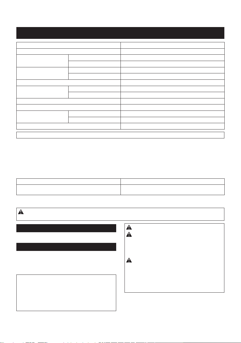
Makita DGP180 User manual

DGP180
EN Cordless Grease Gun INSTRUCTION MANUAL 7
SV Batteridriven smörjpistol BRUKSANVISNING 15
NO Batteridreven smørepistol BRUKSANVISNING 23
FI Akkukäyttöinen rasvapuristin KÄYTTÖOHJE 31
DA Akku fedtpistol BRUGSANVISNING 39
LV Bezvadu eļļošanas pistole LIETOŠANAS INSTRUKCIJA 47
LT Belaidis tepalo pistoletas NAUDOJIMO INSTRUKCIJA 55
ET Juhtmeta määrdeprits KASUTUSJUHEND 63
RU Аккумуляторный
смазочный шприц РУКОВОДСТВО ПО
ЭКСПЛУАТАЦИИ 71

11
1
2
13
14
12
16
17
2
5
5
3
4
15
6
8
9
10
7
Fig.1
2
1
3
Fig.2
1
2
Fig.3
BA
1
1
2
3
Fig.4
2
1
Fig.5
2

1
Fig.6
1
Fig.7
1
Fig.8
1
Fig.9
12
Fig.10
1
2
Fig.11
1
2
1
2
Fig.12
3

1
2
3
Fig.13
1
2
Fig.14
Fig.15
Fig.16
1
Fig.17
Fig.18
1
3
2
Fig.19
5
1
2
3
4
Fig.20
4

Fig.21
1
Fig.22
Fig.23
Fig.24
Fig.25
1
2
Fig.26
1
34
5
2
Fig.27
1
3
2
Fig.28
5

1
2
Fig.29
Fig.30
1
2
Fig.31
1
Fig.32
Fig.33
1
2
Fig.34
1
Fig.35
6

7ENGLISH
ENGLISH (Original instructions)
SPECIFICATIONS
Model: DGP180
Rated voltage D.C. 18 V
Grease capacity
(with A-type barrel)
Cartridge 410 g
Bulk 455 g
Grease capacity
(with B-type barrel)
Cartridge 450 g
Bulk 570 g
Maximum operating pressure 69 MPa
Maximum ow rate Slow speed mode 145 ml/min
Auto speed mode 290 ml/min
Applicable grease type NLGI No.0 - No.2
Hose length 1,200 mm
Overall length With A-type barrel 411 mm
With B-type barrel 449 mm
Net weight 4.8 - 6.1 kg
NOTE: The barrel type (A-type or B-type) varies depending on the country.
• Due to our continuing program of research and development, the specications herein are subject to change
without notice.
• Specications and battery cartridge may dier from country to country.
• The weight may dier depending on the attachment(s), including the battery cartridge. The lightest and heavi-
est combinations, according to EPTA-Procedure 01/2014, are shown in the table.
Applicable battery cartridge and charger
Battery cartridge BL1815N / BL1820B / BL1830B / BL1840B / BL1850B / BL1860B
Charger DC18RC / DC18RD / DC18RE / DC18SD / DC18SE / DC18SF /
DC18SH
• Some of the battery cartridges and chargers listed above may not be available depending on your region of
residence.
WARNING: Only use the battery cartridges and chargers listed above. Use of any other battery cartridges
and chargers may cause injury and/or re.
Intended use
This tool is intended for dispensing grease.
Noise
The typical A-weighted noise level determined accord-
ing to EN62841-1:
Sound pressure level (LpA) : 76 dB(A)
Uncertainty (K) : 3 dB(A)
NOTE: The declared noise emission value(s) has
been measured in accordance with a standard test
method and may be used for comparing one tool with
another.
NOTE: The declared noise emission value(s)
may also be used in a preliminary assessment of
exposure.
WARNING: Wear ear protection.
WARNING: The noise emission during actual
use of the power tool can dier from the declared
value(s) depending on the ways in which the
tool is used especially what kind of workpiece is
processed.
WARNING: Be sure to identify safety mea-
sures to protect the operator that are based on an
estimation of exposure in the actual conditions of
use (taking account of all parts of the operating
cycle such as the times when the tool is switched
o and when it is running idle in addition to the
trigger time).

8ENGLISH
Vibration
The vibration total value (tri-axial vector sum) deter-
mined according to EN62841-1:
Vibration emission (ah) : 2.5 m/s2or less
Uncertainty (K) : 1.5 m/s2
NOTE: The declared vibration total value(s) has been
measured in accordance with a standard test method
and may be used for comparing one tool with another.
NOTE: The declared vibration total value(s) may also
be used in a preliminary assessment of exposure.
WARNING: The vibration emission during
actual use of the power tool can dier from the
declared value(s) depending on the ways in which
the tool is used especially what kind of workpiece
is processed.
WARNING: Be sure to identify safety mea-
sures to protect the operator that are based on an
estimation of exposure in the actual conditions of
use (taking account of all parts of the operating
cycle such as the times when the tool is switched
o and when it is running idle in addition to the
trigger time).
EC Declaration of Conformity
For European countries only
The EC declaration of conformity is included as Annex A
to this instruction manual.
SAFETY WARNINGS
General power tool safety warnings
WARNING: Read all safety warnings, instruc-
tions, illustrations and specications provided
with this power tool. Failure to follow all instructions
listed below may result in electric shock, re and/or
serious injury.
Save all warnings and instruc-
tions for future reference.
The term "power tool" in the warnings refers to your
mains-operated (corded) power tool or battery-operated
(cordless) power tool.
Cordless grease gun safety warnings
1. Hold the tool rmly.
2. Do not operate the tool near ame. The grease
may be ammable.
3. Use only grease that meets the specications
stated in this instruction manual. Installing a
dierent type of grease or any materials other than
grease may cause failure.
4. Do not install any materials other than grease,
such as oil. It may spout out of the tool and get
into eyes.
5. Do not carry the tool by the exible hose or the
rod handle.
6. Wear goggles when using the tool.
7. Check the exible hose before each use. Do
not use the hose if it is kinked or damaged. The
hose may be ruptured by high pressure and the
grease gets into eyes.
8. Make sure the rod is secured rmly. The rod
may move accidently and cause a pinching.
9. Read and follow the instructions of grease
manufacture before usage.
10. Keep hands and clothes away from the rod of
the rod handle. Otherwise your nger or clothes
may be pinched.
11. Wipe o grease adhering on the tool. Otherwise
it may cause slipping and result in an injury.
12. Do not bend the exible hose forcibly or stamp
it. Doing so may cause a breakage or deformation
of the hose.
13. Do not point the adapter at anyone in the
vicinity.
14. Use the exible hose only specied by Makita.
Use of any other hose might present a risk of
injury.
SAVE THESE INSTRUCTIONS.
Important safety instructions for
battery cartridge
1. Before using battery cartridge, read all instruc-
tions and cautionary markings on (1) battery
charger, (2) battery, and (3) product using
battery.
2. Do not disassemble or tamper with the battery
cartridge. It may result in a re, excessive heat,
or explosion.
3. If operating time has become excessively
shorter, stop operating immediately. It may
result in a risk of overheating, possible burns
and even an explosion.
4. If electrolyte gets into your eyes, rinse them
out with clear water and seek medical atten-
tion right away. It may result in loss of your
eyesight.
5. Do not short the battery cartridge:
(1) Do not touch the terminals with any con-
ductive material.
(2) Avoid storing battery cartridge in a con-
tainer with other metal objects such as
nails, coins, etc.
(3) Do not expose battery cartridge to water
or rain.
A battery short can cause a large current
ow, overheating, possible burns and even a
breakdown.
6. Do not store and use the tool and battery car-
tridge in locations where the temperature may
reach or exceed 50 °C (122 °F).
7. Do not incinerate the battery cartridge even if
it is severely damaged or is completely worn
out. The battery cartridge can explode in a re.

9ENGLISH
8. Do not nail, cut, crush, throw, drop the battery
cartridge, or hit against a hard object to the
battery cartridge. Such conduct may result in a
re, excessive heat, or explosion.
9. Do not use a damaged battery.
10. The contained lithium-ion batteries are subject
to the Dangerous Goods Legislation require-
ments.
For commercial transports e.g. by third parties,
forwarding agents, special requirement on pack-
aging and labeling must be observed.
For preparation of the item being shipped, consult-
ing an expert for hazardous material is required.
Please also observe possibly more detailed
national regulations.
Tape or mask o open contacts and pack up the
battery in such a manner that it cannot move
around in the packaging.
11. When disposing the battery cartridge, remove
it from the tool and dispose of it in a safe
place. Follow your local regulations relating to
disposal of battery.
12. Use the batteries only with the products
specied by Makita. Installing the batteries to
non-compliant products may result in a re, exces-
sive heat, explosion, or leak of electrolyte.
13. If the tool is not used for a long period of time,
the battery must be removed from the tool.
14. During and after use, the battery cartridge may
take on heat which can cause burns or low
temperature burns. Pay attention to the han-
dling of hot battery cartridges.
15. Do not touch the terminal of the tool imme-
diately after use as it may get hot enough to
cause burns.
16. Do not allow chips, dust, or soil stuck into the
terminals, holes, and grooves of the battery
cartridge. It may result in poor performance or
breakdown of the tool or battery cartridge.
17. Unless the tool supports the use near
high-voltage electrical power lines, do not use
the battery cartridge near high-voltage electri-
cal power lines. It may result in a malfunction or
breakdown of the tool or battery cartridge.
18. Keep the battery away from children.
SAVE THESE INSTRUCTIONS.
CAUTION: Only use genuine Makita batteries.
Use of non-genuine Makita batteries, or batteries that
have been altered, may result in the battery bursting
causing res, personal injury and damage. It will
also void the Makita warranty for the Makita tool and
charger.
Tips for maintaining maximum
battery life
1. Charge the battery cartridge before completely
discharged. Always stop tool operation and
charge the battery cartridge when you notice
less tool power.
2. Never recharge a fully charged battery car-
tridge. Overcharging shortens the battery
service life.
3. Charge the battery cartridge with room tem-
perature at 10 °C - 40 °C (50 °F - 104 °F). Let
a hot battery cartridge cool down before
charging it.
4. When not using the battery cartridge, remove
it from the tool or the charger.
5. Charge the battery cartridge if you do not use
it for a long period (more than six months).
PARTS DESCRIPTION
► Fig.1
1Switch trigger 2Lock button 3Lamp switch
4Lamp 5Trigger-lock button 6Speed mode changing knob
7Air drain 8Filler port plug 9Flexible hose
10 Adapter 11 Strap hole 12 Battery cartridge
13 Barrel 14 Rod handle 15 Hose holder
16 Pressure relief valve 17 Shoulder strap - -

10 ENGLISH
FUNCTIONAL DESCRIPTION
CAUTION: Always be sure that the tool is
switched o and the battery cartridge is removed
before adjusting or checking function on the tool.
Installing or removing battery cartridge
CAUTION: Always switch o the tool before
installing or removing of the battery cartridge.
CAUTION:
Hold the tool and the battery cartridge
rmly when installing or removing battery cartridge.
Failure to hold the tool and the battery cartridge rmly may
cause them to slip o your hands and result in damage to
the tool and battery cartridge and a personal injury.
► Fig.2: 1. Red indicator 2. Button 3. Battery cartridge
To remove the battery cartridge, slide it from the tool
while sliding the button on the front of the cartridge.
To install the battery cartridge, align the tongue on the
battery cartridge with the groove in the housing and slip
it into place. Insert it all the way until it locks in place
with a little click. If you can see the red indicator on the
upper side of the button, it is not locked completely.
CAUTION: Always install the battery cartridge
fully until the red indicator cannot be seen. If not,
it may accidentally fall out of the tool, causing injury to
you or someone around you.
CAUTION: Do not install the battery cartridge
forcibly. If the cartridge does not slide in easily, it is
not being inserted correctly.
Tool / battery protection system
The tool is equipped with a tool/battery protection sys-
tem. This system automatically cuts o power to the
motor to extend tool and battery life. The tool will auto-
matically stop during operation if the tool or battery is
placed under one of the following conditions:
Overload protection
When the tool/battery is operated in a manner that causes
it to draw an abnormally high current, the tool automat-
ically stops without any indication. In this situation, turn
the tool o and stop the application that caused the tool to
become overloaded. Then turn the tool on to restart.
Overheat protection
When the tool or battery is overheated, the tool stops
automatically and the lamp blinks. In this case, let the
tool and battery cool before turning the tool on again.
Overdischarge protection
When the battery capacity is not enough, the tool stops
automatically. In this case, remove the battery from the
tool and charge the battery.
NOTE: The protection system may become more
likely to work depending on the ambient temperature
or the type and condition of grease.
Indicating the remaining battery
capacity
Only for battery cartridges with the indicator
► Fig.3: 1. Indicator lamps 2. Check button
Press the check button on the battery cartridge to indi-
cate the remaining battery capacity. The indicator lamps
light up for a few seconds.
Indicator lamps Remaining
capacity
Lighted O Blinking
75% to 100%
50% to 75%
25% to 50%
0% to 25%
Charge the
battery.
The battery
may have
malfunctioned.
NOTE: Depending on the conditions of use and the
ambient temperature, the indication may dier slightly
from the actual capacity.
NOTE: The rst (far left) indicator lamp will blink when
the battery protection system works.
Switch action
CAUTION: Before installing the battery car-
tridge into the tool, always check to see that the
switch trigger actuates properly and returns to
the "OFF" position when released.
CAUTION: When not operating the tool,
depress the trigger-lock button from "A" side to
lock the switch trigger in the OFF position.
To prevent the switch trigger from accidentally pulled,
the trigger-lock button is provided.
To start the tool, depress the trigger-lock button from "B"
side and pull the switch trigger.
Tool speed is increased by increasing pressure on the
switch trigger. Release the switch trigger to stop. After
use, always press in the trigger-lock button from "A"
side.
For continuous operation, pull the switch trigger and
then push in the lock button. To stop the tool from the
locked position, pull the switch trigger fully to unlock.
► Fig.4: 1. Switch trigger 2. Lock button 3. Trigger-
lock button

11 ENGLISH
Lighting up the front lamp
CAUTION: Do not look in the light or see the
source of light directly.
Press the lamp switch to light up the lamp. Press the
lamp switch again to turn o the lamp. When the tool is
left without any operation for about 60 seconds with the
motor stopped, the lamp goes out.
► Fig.5: 1. Lamp 2. Lamp switch
NOTICE: Use a dry cloth to wipe the dirt o the lens
of the lamp. Be careful not to scratch the lens of lamp,
or it may lower the illumination.
Selecting the speed mode
NOTICE: Change the speed mode only after the
tool comes to a complete stop.
The tool employs the speed mode changing knob. Turn
the knob so that the arrow on the knob points toward
one of the two modes below;
1Slow speed mode: Dispense grease at constant slow
speed.
2Auto speed mode: Apply grease while varying the
ow rate automatically according to pressure of supply
destination.
► Fig.6: 1. Speed mode changing knob
Pressure relief valve
When the internal pressure in the tool exceeds a certain
level, grease comes out from the pressure relief valve to
lower the internal pressure.
► Fig.7: 1. Pressure relief valve
CAUTION: When grease comes out from the
pressure relief valve, wipe o the grease with a
dry cloth or the like. Otherwise it may cause slipping
and result in an injury.
ASSEMBLY
CAUTION: Always be sure that the tool is
switched o and the battery cartridge is removed
before carrying out any work on the tool.
Removing or installing barrel
To remove the barrel, screw it as illustrated.
► Fig.8: 1. Barrel
To install the barrel, insert it into the tool then screw in
reverse.
► Fig.9: 1. Barrel
Rod handle
Pull the rod handle when installing grease in the barrel.
► Fig.10: 1. Rod handle 2. Rod
To lock the rod handle fully pulled, pull the rod handle
until the groove on the rod can be seen, and then hook
the groove onto the slot. To unlock the rod handle,
unhook the groove so the rod moves forward.
► Fig.11: 1. Groove 2. Slot
CAUTION: Make sure the rod handle is locked
rmly. Otherwise it may be unlocked accidentally and
cause a pinching.
NOTE: To pull the rod handle while the barrel
installed in the tool, loosen the valve of the air drain to
let air comes into the barrel.
Hose holder
The hose holder can be attached to either side of the
tool with the screw.
► Fig.12: 1. Hose holder 2. Screw
Shoulder strap
WARNING: Never use the strap hole for lan-
yard (tether strap). Doing so may result in serious
injury because the strap hole is not intended for a
safety device for fall prevention.
WARNING: When carrying the tool, keep
holding the tool even if when using the shoulder
strap. Carrying the tool using only the shoulder strap
makes it unstable. The shoulder strap may come o
or the tool hit other objects and cause injury.
Attach the hooks of the shoulder strap onto the mounts
of the strap holes as shown in the gure.
► Fig.13: 1. Shoulder strap 2. Hook 3. Mount
OPERATION
Grease supply
WARNING: Make sure to read the instruction
manuals of the grease and/or other instruments
and replace the following contents as necessary.
Misuse or failure to follow the instructions may dam-
age the tool or cause an injury.
NOTICE: When using the barrel with the old
grease remains, remove the barrel and purge the
old grease according to the section for purge of
grease.

12 ENGLISH
There are following ways to provide grease:
Installing grease cartridge
(commercially-bought) in the barrel
NOTICE: (For A-type barrel only)
Use the grease cartridge whose brim can be
hooked on the end surface of the barrel.
NOTICE: (For B-type/C-type barrel only)
Use the grease cartridge whose brim can be
hooked on the inside step of the barrel.
1. Remove the barrel from the tool then fully pull the
rod handle and lock it.
2. Remove the plastic cap of the grease cartridge
and insert the grease cartridge into the barrel.
► Fig.14: 1. Grease cartridge (commercially-bought)
2. Pull tab
3. Remove the pull tab of the grease cartridge then
install the barrel to the tool.
If there is a gap between the brim of the grease car-
tridge and the barrel, screw the barrel into the tool while
pushing the barrel forward.
► Fig.15
4. Release the rod handle.
► Fig.16
5. Eject the air that remains in the ow path of the
grease. (Refer to the section for ejection of air.)
Filling grease in the barrel
from a bulk container
(commercially-bought)
1. Remove the barrel from the tool.
2. Dip the tip of the barrel in the grease and then
pull the rod handle. The grease is pumped up into the
barrel.
► Fig.17: 1. Bulk container (commercially-bought)
3. Fully pull the rod handle and lock it.
► Fig.18
4. Install the barrel to the tool and then unlock the
rod handle.
5. Eject the air that remains in the ow path of the
grease. (Refer to the section for ejection of air.)
NOTICE: When locking the rod handle, make
sure the rod handle is locked rmly. Otherwise the
rod handle get unlocked unintentionally, the grease
comes out from the barrel.
NOTE: (For B-type/C-type barrel only)
The amount of grease lling should be below the
screw groove line. Otherwise grease will overow
when installing the barrel to the tool.
► Fig.19: 1. Barrel (B-type/C-type) 2. Screw groove
3. Grease
You can also ll grease into the barrel using a ller
pump (commercially-bought) attached to the bulk
container.
1. Remove the ller port plug. Attach a loader tting
(commercially-bought) to the ller port.
2. With the barrel installed in the tool, connect the
loader tting to the tting of the ller pump.
► Fig.20: 1. Filler port plug 2. Filler port 3. Loader
tting (commercially-bought) 4. Filler pump
(commercially-bought) 5. Fitting
3. Operate the ller pump. The rod of the rod handle
will be pushed out as the barrel is lled with grease.
► Fig.21
4. Disconnect the loader tting from the tting of the
ller pump.
5. Eject the air that remains in the ow path of the
grease. (Refer to the section for ejection of air.)
WARNING: Use a low-pressure loader tting
only. Never use a high-pressure loader tting
otherwise it may damage the tool and cause a
personal injury.
CAUTION: Hold the tool rmly when lling the
grease by using a ller pump. The tool may fall and
cause an injury.
NOTICE: Stop lling the grease when you see
the groove on the rod. Otherwise the grease leak-
age may occur.
Ejection of air
If air remains in the ow path of the grease, the tool
cannot pour grease accurately. Eject the air before each
use and also when the tool seems to work improperly
due to air.
1. To eject air from inside of the tool, loosen the valve
for air drain. Air comes out from the hole for air drain.
2. Fasten the valve when you see the grease coming
out of the hole.
► Fig.22: 1. Valve
WARNING: Wear the protective goggles when
ejecting the air.
CAUTION: Wipe o the grease that comes
out from the air drain with a dry cloth or the like.
Otherwise it may cause slipping and result in an
injury.
Dispensing the grease
In the following cases, purge the old grease inside the
tool before use;
— When using the tool for the rst time or;
— When using dierent type of the grease from
previous use.
With the new grease lled in the barrel, run the tool
for a while until the old grease is pushed out from the
adapter.

13 ENGLISH
NOTICE: Do not connect the adapter to the
grease nipple until the old grease is purged. If
dierent kinds of grease are mixed, the performance
of the grease may decline.
NOTE: The tool has been tested at the factory and
small amount of the grease remains.
Perform the following procedure to dispense the
grease.
CAUTION: Always check the speed mode
before operation.
NOTICE: Before connecting the adapter to the
grease nipple, always make sure that the tool
dispenses grease properly.
NOTICE: Do not connect the adapter to the
grease nipple forcibly.
1. Wipe the adapter and the grease nipple before
connecting. Push the adapter straight at the grease
nipple.
2. Pull the switch trigger to dispense the grease.
► Fig.23
3. When dispensing the grease is nished, remove
the adapter from the grease nipple. Tilt the adapter
slightly to release internal pressure and then remove
the adapter from the grease nipple.
Wipe o the grease from the adapter and the grease
nipple.
NOTICE: Do not leave the tool running even after
the grease depleted. It may shorten the life of the
tool.
NOTE: If the internal pressure rises while the switch
trigger is not fully pulled, the protection system works
and the motor will stop even though the tool does
not reach the maximum operating pressure. When
injecting the grease at high pressure, pull the switch
trigger fully.
NOTE: The tool stops automatically when the tool
keep running for more than 6 minutes.
MAINTENANCE
CAUTION: Always be sure that the tool is
switched o and the battery cartridge is removed
before attempting to perform inspection or
maintenance.
NOTICE: Never use gasoline, benzine, thinner,
alcohol or the like. Discoloration, deformation or
cracks may result.
To maintain product SAFETY and RELIABILITY,
repairs, any other maintenance or adjustment should
be performed by Makita Authorized or Factory Service
Centers, always using Makita replacement parts.
Purge of grease
When storing the tool or using the barrel in which the
grease remains, remove the barrel and purge the old
grease in the following procedure.
1. Loosen the valve for air drain.
2. Fully pull the rod handle and lock it.
3. Remove the barrel from the tool.
4. Unlock the rod handle. Keep holding the rod
handle and slowly move the rod handle forward so the
grease gets out of the barrel.
CAUTION: Do not take hand o from the rod
handle. Otherwise the grease pops out vigorously.
NOTICE: Keep dust away from inside of the
barrel. Dust may get clogged in the tool.
NOTICE: Clean the inside of the barrel once
every three months.
OPTIONAL
ACCESSORIES
CAUTION: These accessories or attachments
are recommended for use with your Makita tool
specied in this manual. The use of any other
accessories or attachments might present a risk of
injury to persons. Only use accessory or attachment
for its stated purpose.
If you need any assistance for more details regard-
ing these accessories, ask your local Makita Service
Center.
• Adapter
• Flexible hose
• Barrel
• Cartridge barrel
• Shoulder strap
• Lock on adapter
• Angle adapter
• Makita genuine battery and charger
NOTE: Some items in the list may be included in the
tool package as standard accessories. They may
dier from country to country.
Replacing of the adapter
Loosen and remove the old adapter with two wrenches
as illustrated and then tighten the new adapter securely.
► Fig.24
NOTE: If grease leaks from the joint between the
hose and the adapter, wrap thread seal tape around
the thread part of the hose before connecting the
adapter.

14 ENGLISH
Replacing of the exible hose
Loosen and remove the old exible hose with a wrench as
illustrated and then tighten the new exible hose securely.
► Fig.25
CAUTION: Replace the rubber ring attached
to the connection part of the new exible hose at
the same time. If you replace the exible hose with-
out the rubber ring or with the old rubber ring, grease
may leak and cause an injury.
Changing the barrel
NOTE:
The barrel type varies depending on the country.
NOTE: To install a barrel of dierent type, additional
parts described below are required depending on the
type of the barrel.
Changing the barrel from A-type to
B-type/C-type
1. Remove A-type barrel.
2. Remove the screw and then the sleeve.
► Fig.26: 1. Sleeve 2. Screw
3. Insert the joint with the rubber packing while align-
ing the tab with the groove on the mounting part and
then secure it with screws.
4. Install B-type/C-type barrel.
► Fig.27: 1. Joint 2. Rubber packing 3. Tab 4. Groove
5. Screw
Changing the barrel from B-type/C-
type to A-type
1. Remove B-type/C-type barrel.
2. Unscrew and remove the joint.
► Fig.28: 1. Joint 2. Rubber packing 3. Screw
3. Insert the sleeve into the tool housing, then secure
it with a screw.
4. Install A-type barrel.
► Fig.29: 1. Sleeve 2. Screw
Cartridge barrel
You can see the grease cartridge through the hole on
the cartridge barrel.
► Fig.30
When using the cartridge barrel, transfer the piston parts
from the corresponding barrel to the cartridge barrel.
► Fig.31: 1. Piston parts 2. Cartridge barrel
If it is hard to pull out the rod handle, follow the proce-
dure below.
1. Insert the empty grease cartridge into the barrel.
► Fig.32: 1. Empty grease cartridge
2. Pull the the rod handle and lock it.
► Fig.33
3. Remove the empty grease cartridge from the
barrel.
Lock on adapter
CAUTION: Be careful not to pinch the nger
in the lock on adapter.
CAUTION: Wear the protective goggles.
When removing the lock on adapter from the grease
nipple, the grease may spout out of the tool and
cause an injury.
When connecting the lock on adapter to the grease
nipple, push the lock on adapter straight at the grease
nipple while pulling the lever of the lock on adapter, then
release the lever.
► Fig.34: 1. Lever 2. Lock on adapter
To assemble the lock on adapter, refer to the section for
replacing of the adapter.
Angle adapter
When attaching the angle adapter, push the adapter of
the tool straight to the angle adapter.
► Fig.35: 1. Angle adapter

15 SVENSKA
SVENSKA (Originalinstruktioner)
SPECIFIKATIONER
Modell: DGP180
Märkspänning 18 V likström
Smörjkapacitet
(med cylinder av A-typ)
Patron 410 g
Bulk 455 g
Smörjkapacitet
(med cylinder av B-typ)
Patron 450 g
Bulk 570 g
Max drifttryck 69 MPa
Max ödeshastighet Låghastighetsläge 145 ml/min
Autohastighetsläge 290 ml/min
Tillämplig fettyp NLGI nr0 - nr2
Slanglängd 1 200 mm
Total längd Med cylinder av A-typ 411 mm
Med cylinder av B-typ 449 mm
Nettovikt 4,8 - 6,1 kg
OBS: Cylindertypen (A-typ eller B-typ) varierar beroende på land.
• På grund av vårt pågående program för forskning och utveckling kan dessa specikationer ändras utan föregå-
ende meddelande.
• Specikationer och batterikassett kan variera mellan olika länder.
• Vikten kan variera beroende på tillbehören, inklusive batterikassett. Den lättaste och den tyngsta kombinatio-
nen enligt EPTA-procedur 01/2014 visas i tabellen.
Tillgänglig batterikassett och laddare
Batterikassett BL1815N / BL1820B / BL1830B / BL1840B / BL1850B / BL1860B
Laddare DC18RC / DC18RD / DC18RE / DC18SD / DC18SE / DC18SF /
DC18SH
• Vissa av batterikassetterna och laddarna på listan ovan kanske inte nns tillgängliga i din region.
VARNING: Använd endast batterikassetter och laddare från listan ovan. Användning av andra batterikas-
setter och laddare kan orsaka personskada och/eller brand.
Avsedd användning
Detta verktyg är avsett för att portionera ut fett.
Buller
Den normala bullernivån för A-belastning är bestämd
enligt EN62841-1:
Ljudtrycksnivå (LpA) : 76 dB (A)
Mättolerans (K): 3 dB (A)
OBS: Det deklarerade bullervärdet har uppmätts i
enlighet med standardtestmetoden och kan användas
för jämförandet av en maskin med en annan.
OBS: Det deklarerade bulleremissionsvärdet kan
också användas i en preliminär bedömning av expo-
nering för vibration.
VARNING: Använd hörselskydd.
VARNING: Bulleremissionen under faktisk
användning av maskinen kan skilja sig från det
deklarerade värdet, beroende på hur maskinen
används och särskilt vilken typ av arbetsstycke
som behandlas.
VARNING: Var noga med att identiera säker-
hetsåtgärder för att skydda användaren, vilka är
grundade på en uppskattning av graden av expo-
nering för vibrationer under de faktiska använd-
ningsförhållandena, (ta, förutom avtryckartiden,
med alla delar av användarcykeln i beräkningen,
som till exempel tiden då maskinen är avstängd
och när den går på tomgång).

16 SVENSKA
Vibration
Det totala vibrationsvärdet (treaxlad vektorsumma)
bestämt enligt EN62841-1:
Vibrationsemission (ah) : 2,5 m/s2eller lägre
Mättolerans (K): 1,5 m/s2
OBS: Det deklarerade totala vibrationsvärdet har
uppmätts i enlighet med standardtestmetoden och
kan användas för jämförandet av en maskin med en
annan.
OBS: Det deklarerade totala vibrationsvärdet kan
också användas i en preliminär bedömning av expo-
nering för vibration.
VARNING: Vibrationsemissionen under fak-
tisk användning av maskinen kan skilja sig från
det deklarerade värdet, beroende på hur maski-
nen används och särskilt vilken typ av arbetss-
tycke som behandlas.
VARNING: Var noga med att identiera säker-
hetsåtgärder för att skydda användaren, vilka är
grundade på en uppskattning av graden av expo-
nering för vibrationer under de faktiska använd-
ningsförhållandena, (ta, förutom avtryckartiden,
med alla delar av användarcykeln i beräkningen,
som till exempel tiden då maskinen är avstängd
och när den går på tomgång).
EG-försäkran om överensstämmelse
Gäller endast inom EU
EG-försäkran om överensstämmelse inkluderas som
bilaga A till denna bruksanvisning.
SÄKERHETSVARNINGAR
Allmänna säkerhetsvarningar för
maskiner
VARNING: Läs alla säkerhetsvarningar, anvis-
ningar, illustrationer och specikationer som
medföljer det här maskinen. Underlåtenhet att följa
instruktionerna kan leda till elstötar, brand och/eller
allvarliga personskador.
Spara alla varningar och instruk-
tioner för framtida referens.
Termen ”maskin” som anges i varningarna hänvisar till
din eldrivna maskin (sladdansluten) eller batteridrivna
maskin (sladdlös).
Säkerhetsvarningar för batteridriven
smörjpistol
1. Håll stadigt i maskinen.
2. Använd inte verktyget nära eld. Fettet kan
antändas.
3. Använd endast fett som uppfyller de specika-
tioner som anges i denna bruksanvisning. Att
lägga i en annan typ av fett eller andra material än
fett kan orsaka fel.
4. Lägg inte i andra material än fett, t.ex. olja. Det
kan spruta ut ur verktyget och komma i ögonen.
5. Bär inte verktyget i den exibla slangen eller
stånghandtaget.
6. Ha på glasögon när verktyget används.
7. Kontrollera den exibla slangen före varje
användning. Använd inte slangen om den är
vriden eller skadad. Det kan bli brott på slangen
genom det höga trycket så att fettet kommer i
ögonen.
8. Se till att stången sitter ordentligt fast. Stången
kan råka röra sig och orsaka klämning.
9. Läs och följ fettillverkarens instruktioner före
användning.
10. Håll händer och klädesplagg borta från
stången på stånghandtaget. Annars kan du få
ett nger eller kläderna i kläm.
11. Torka av fett som är kvar på verktyget. Annars
kan det orsaka halkning och leda till skada.
12. Böj inte den exibla slangen med våld och
stampa inte på den. Att göra detta kan göra att
slangen går av eller deformeras.
13. Rikta inte adaptern mot andra personer.
14. Använd endast sådan exibel slang som spe-
ciceras av Makita. Att använda någon annan
slang kan utgöra risk för skada.
SPARA DESSA ANVISNINGAR.
Viktiga säkerhetsanvisningar för
batterikassetten
1. Innan batterikassetten används ska alla
instruktioner och varningsmärken på (1) bat-
teriladdaren, (2) batteriet och (3) produkten
läsas.
2. Montera inte isär eller mixtra med batterikas-
setten. Det kan leda till brand, överdriven värme
eller explosion.
3. Om drifttiden blivit avsevärt kortare ska
användningen avbrytas omedelbart. Det kan
uppstå överhettning, brännskador och t o m en
explosion.
4. Om du får elektrolyt i ögonen ska de sköljas
med rent vatten och läkare uppsökas omedel-
bart. Det nns risk för att synen förloras.
5. Kortslut inte batterikassetten.
(1) Rör inte vid polerna med något strömfö-
rande material.
(2) Undvik att förvara batterikassetten till-
sammans med andra metallobjekt som
t.ex. spikar, mynt o.s.v.
(3) Skydda batteriet mot vatten och regn.

17 SVENSKA
En batterikortslutning kan orsaka ett
stort strömöde, överhettning, brand och
maskinhaveri.
6. Förvara och använd inte verktyget och batteri-
kassetten på platser där temperaturen kan nå
eller överstiga 50 °C.
7. Bränn inte upp batterikassetten även om
den är svårt skadad eller helt utsliten.
Batterikassetten kan explodera i öppen eld.
8. Spika inte i, krossa, kasta, tappa eller slå bat-
terikassetten mot hårda föremål. Dylika hän-
delser kan leda till brand, överdriven värme eller
explosion.
9. Använd inte ett skadat batteri.
10. De medföljande litiumjonbatterierna är föremål
för kraven i gällande lagstiftning för farligt
gods.
För kommersiella transporter (av t.ex. tredje parter
som speditionsrmor) måste de särskilda trans-
portkrav som anges på emballaget och etiketter
iakttas.
För att förbereda den produkt som ska avsändas
krävs att du konsulterar en expert på riskmaterial.
Var också uppmärksam på att det i ditt land kan
nnas ytterligare föreskrifter att följa.
Tejpa över eller maskera blottade kontakter och
packa batteriet på sådant sätt att det inte kan röra
sig fritt i förpackningen.
11. När batterikassetten ska kasseras måste den
tas bort från maskinen och kasseras på ett
säkert sätt. Följ lokala föreskrifter beträande
avfallshantering av batteriet.
12. Använd endast batterierna med de produkter
som specicerats av Makita. Att använda bat-
terierna med ej godkända produkter kan leda till
brand, överdriven värme, explosion eller utläck-
ande elektrolyt.
13. Om maskinen inte används under en lång tid
måste batteriet tas bort från maskinen.
14. Under och efter användning kan batterikasset-
ten bli het vilket kan orsaka brännskador eller
lättare brännskador. Var uppmärksam på hur
du hanterar varma batterikassetter.
15. Vidrör inte verktygets kontakter direkt efter
användning eftersom de kan bli heta och
orsaka brännskador.
16. Låt inte isor, damm eller smuts fastna i kon-
takterna, i hål eller spår i batterikassetten. Det
kan leda till dålig prestanda eller till att verktyget
eller batterikassetten går sönder.
17. Såvida inte verktyget stöder arbeten i närheten
av högspänningsledningar får batterikassetten
inte användas i närheten av en högspännings-
ledning. Det kan leda till att verktyget eller batteri-
kassetten går sönder eller inte fungerar korrekt.
18. Förvara batteriet utom räckhåll för barn.
SPARA DESSA ANVISNINGAR.
FÖRSIKTIGT: Använda endast äkta Makita-
batterier. Användning av oäkta Makita-batterier eller
batterier som har manipulerats kan leda till person-
och utrustningsskador eller till att batteriet fattar eld.
Det upphäver också Makitas garanti för verktyget och
laddaren.
Tips för att uppnå batteriets max-
imala livslängd
1. Ladda batterikassetten innan den är helt
urladdad. Stanna alltid maskinen och ladda
batterikassetten när du märker att maskinen
blir svagare.
2. Ladda aldrig en fulladdad batterikassett.
Överladdning förkortar batteriets livslängd.
3. Ladda batterikassetten vid en rumstemperatur
på 10 °C - 40 °C. Låt en varm batterikassett
svalna innan den laddas.
4. När batterikassetten inte används ska den tas
bort från verktyget eller laddaren.
5. Ladda batterikassetten om du inte har använt
den på länge (mer än sex månader).
BESKRIVNING AV DELAR
► Fig.1
1Avtryckare 2Låsknapp 3Lampknapp
4Lampa 5Startspärr 6Spak för byte av hastighetsläge
7Luftutsläpp 8Plugg för påfyllningsöppning 9Flexibel slang
10 Adapter 11 Remhål 12 Batterikassett
13 Cylinder 14 Stånghandtag 15 Slangfäste
16 Övertrycksventil 17 Axelrem - -

18 SVENSKA
FUNKTIONSBESKRIVNING
FÖRSIKTIGT: Se alltid till att maskinen är
avstängd och batterikassetten borttagen innan
du justerar maskinen eller kontrollerar dess
funktioner.
Montera eller demontera batterikassetten
FÖRSIKTIGT: Stäng alltid av maskinen innan
du monterar eller tar bort batterikassetten.
FÖRSIKTIGT: Håll stadigt i maskinen och
batterikassetten när du monterar eller tar bort
batterikassetten. I annat fall kan det leda till att de
glider ur dina händer och orsakar skada på maskinen
och batterikassetten samt personskada.
► Fig.2: 1. Röd indikator 2. Knapp 3. Batterikassett
Ta bort batterikassetten genom att skjuta ner knappen på
kassettens framsida samtidigt som du drar ut batterikassetten.
Sätt i batterikassetten genom att rikta in tungan på batterikasset-
ten mot spåret i höljet och skjuta den på plats. Tryck in kassetten
hela vägen tills den låser fast med ett klick. Om du kan se den
röda indikatorn på knappens ovansida är den inte låst ordentligt.
FÖRSIKTIGT: Sätt alltid i batterikassetten
helt tills den röda indikatorn inte längre syns. I
annat fall kan den oväntat falla ur verktyget och skada
dig eller någon annan.
FÖRSIKTIGT: Montera inte batterikassetten
med våld. Om kassetten inte lätt glider på plats är
den felinsatt.
Skyddssystem för maskinen/batteriet
Verktyget är utrustat med ett skyddssystem för verkty-
get/batteriet. Detta system bryter automatiskt strömmen
till motorn för att förlänga verktygets och batteriets
livslängd. Verktyget stoppar automatiskt under använd-
ningen om verktyget eller batteriet hamnar i en av föl-
jande situationer:
Överbelastningsskydd
Om verktyget/batteriet används på ett sätt som gör att
det drar onormalt mycket ström kan det stoppas auto-
matiskt utan varning. När detta sker stänger du av verk-
tyget och upphör med arbetet som gjorde att verktyget
överbelastades. Starta därefter upp verktyget igen.
Överhettningsskydd
När verktyget eller batteriet överhettas stoppas det automa-
tiskt och lampan börjar blinka. I sådant fall ska du låta verk-
tyget och batteriet svalna innan du startar verktyget igen.
Överurladdningsskydd
När batteriets kapacitet är otillräcklig stoppar maskinen auto-
matiskt. I sådant fall ska batteriet tas ur maskinen och laddas.
OBS: Det är mer sannolikt att skyddssystemet funge-
rar beroende på omgivningstemperaturen eller fettets
typ och skick.
Indikerar kvarvarande
batterikapacitet
Endast för batterikassetter med indikator
► Fig.3: 1. Indikatorlampor 2. Kontrollknapp
Tryck på kontrollknappen på batterikassetten för att se
kvarvarande batterikapacitet. Indikatorlamporna lyser i
ett par sekunder.
Indikatorlampor Kvarvarande
kapacitet
Upplyst Av Blinkar
75% till 100%
50% till 75%
25% till 50%
0% till 25%
Ladda
batteriet.
Batteriet kan
ha skadats.
OBS: Beroende på användningsförhållanden och den
omgivande temperaturen kan indikationen skilja sig
lätt från den faktiska batterikapaciteten.
OBS: Den första (längst till vänster) indikatorlam-
pan kommer att blinka när batteriskyddssystemet
fungerar.
Avtryckarens funktion
FÖRSIKTIGT: Innan du sätter i batterikasset-
ten i maskinen ska du kontrollera att avtryckaren
fungerar och återgår till läget ”OFF” när du släp-
per den.
FÖRSIKTIGT: När verktyget inte används ska
startspärren vara intryckt från ”A”-sidan för att
låsa avtryckaren i det avstängda läget OFF.
Startspärren förhindrar att avtryckaren råkar utlösas
oavsiktligt.
Tryck in låsknappen för avtryckaren från ”B”-sidan och
tryck sedan in avtryckaren för att starta verktyget.
Verktygets hastighet ökas genom att avtryckaren trycks
in hårdare. Släpp avtryckaren för att stoppa verktyget.
Tryck in startspärren från ”A”-sidan efter användning.
För kontinuerlig användning trycker du först in avtryck-
aren och sedan spärrknappen. För att stoppa verktyget
från det låsta läget trycker du på avtryckaren för att låsa
upp.
► Fig.4: 1. Avtryckarknapp 2. Låsknapp 3. Startspärr

19 SVENSKA
Tända frontlampan
FÖRSIKTIGT: Titta inte in i ljuset eller direkt
i ljuskällan.
Tryck på lampknappen för att tända lampan. Tryck på
lampknappen igen för att släcka lampan. När verktyget
lämnas oanvänt i omkring 60 sekunder med motorn
stoppad, släcks lampan.
► Fig.5: 1. Lampa 2. Lampknapp
OBSERVERA: Använd en torr trasa för att torka
bort smuts från lampglaset. Var försiktig så att inte
lampglaset repas eftersom ljuset då kan bli svagare.
Välja hastighetsläge
OBSERVERA: Ändra hastighetsläget först när
verktyget har stannat helt.
Verktyget använder sig av ett reglage för byte av hastig-
hetsläge. Vrid reglaget så att pilen på det pekar på ett
av de två lägena nedan:
1Låghastighetsläge: Fördela fett i konstant låg
hastighet.
2Autohastighetsläge: Lägg på fett samtidigt som ödes-
hastigheten varieras automatiskt beroende på trycket i
målet för tillförseln.
► Fig.6: 1. Spak för byte av hastighetsläge
Övertrycksventil
När det inre trycket i verktyget överstiger en viss nivå,
kommer fett ut från övertrycksventilen så att det inre
trycket sänks.
► Fig.7: 1. Övertrycksventil
FÖRSIKTIGT: När fett kommer ut från över-
trycksventilen, torkar du av det med en torr trasa
eller liknande. Annars kan det orsaka halkning och
leda till skada.
MONTERING
FÖRSIKTIGT: Se alltid till att maskinen är
avstängd och batterikassetten borttagen innan du
underhåller maskinen.
Ta bort eller installera cylindern
Ta bort cylindern genom att skruva på den enligt bilden.
► Fig.8: 1. Cylinder
Installera cylindern genom att sätta in den i verktyget
och sedan skruva bakåt.
► Fig.9: 1. Cylinder
Stånghandtag
Dra i stånghandtaget när du lägger in fett i cylindern.
► Fig.10: 1. Stånghandtag 2. Stång
För att låsa stånghandtaget i helt utdraget läge drar du
i det tills det går att se räan på stången, och hakar
sedan fast räan i skåran. Lås upp stånghandtaget
genom att haka av räan så att stången rör sig framåt.
► Fig.11: 1. Räa 2. Skåra
FÖRSIKTIGT: Se till att stånghandtaget är
ordentligt låst. I annat fall kan det låsas upp av
misstag och orsaka klämning.
OBS: För att dra i stånghandtaget medan cylindern
är installerad i verktyget lossar du luftutsläppsventilen
så luft kommer in i cylindern.
Slangfäste
Slangfästet kan fästas på någondera sidan av verktyget
med skruven.
► Fig.12: 1. Slangfäste 2. Skruv
Axelrem
VARNING: Använd aldrig remhålet för rep
(fästrem). Att göra detta kan leda till allvarlig skada
eftersom remhålet inte är avsett för en säkerhetsan-
ordning för fallskydd.
VARNING: När du bär verktyget ska du fort-
sätta hålla i verktyget även om du använder axel-
remmen. Om du bär verktyget endast i axelremmen
blir den instabil. Axelremmen kan åka av, eller så kan
verktyget slå mot andra föremål och orsaka skada.
Fäst axelremmens krokar på remhålens fästen enligt
bilden.
► Fig.13: 1. Axelrem 2. Krok 3. Fäste
ANVÄNDNING
Fettillförsel
VARNING: Se till att läsa bruksanvisningarna
till fettet och/eller andra instrument och byt ut föl-
jande innehåll om det behövs. Felaktig användning
eller instruktioner som inte följs kan skada verktyget
eller orsaka skada.
OBSERVERA: När du använder cylindern med
de gamla fettresterna, ta då bort cylindern och
rensa bort det gamla fettet enligt avsnittet om
borttagning av fett.

20 SVENSKA
Följande sätt nns att tillhandahålla fett:
Installera fettpatron (köps i handeln)
i cylindern
OBSERVERA: (Endast för cylinder av A-typ)
Använd en fettpatron vars kant kan krokas fast på
tunnans ovansida.
OBSERVERA: (Endast för cylinder av B-typ/C-typ)
Använd en fettpatron vars kant kan krokas fast på
tunnans invändiga steg.
1. Ta bort cylindern från verktyget, dra sedan ut
stånghandtaget helt och lås det.
2. Ta bort fettpatronens plastlock och sätt in fettpa-
tronen i cylindern.
► Fig.14: 1. Fettpatron (köps i handeln) 2. Dragik
3. Ta bort fettpatronens dragik och sätt sedan in
cylindern i verktyget.
Om det är ett spel mellan fettpatronens kant och tunnan
ska tunnan skruvas in i verktyget samtidigt som den
skjuts framåt.
► Fig.15
4. Släpp stånghandtaget.
► Fig.16
5. Spruta ut luften som är kvar i fettets ödesväg. (Se
avsnittet om utsprutning av luft.)
Fylla på fett i cylindern från en
bulkbehållare (köps i handeln)
1. Ta bort cylindern från verktyget.
2. Doppa cylinderns spets i fettet och dra sedan i
stånghandtaget. Fettet pumpas upp i cylindern.
► Fig.17: 1. Bulkbehållare (köps i handeln)
3. Dra ut stånghandtaget helt och lås det.
► Fig.18
4. Sätt in cylindern i verktyget och lås sedan upp
stånghandtaget.
5. Spruta ut luften som är kvar i fettets ödesväg. (Se
avsnittet om utsprutning av luft.)
OBSERVERA: När du låser stånghandtaget, se
då till att det låses ordentligt. I annat fall kan stång-
handtaget låsas upp oavsiktligt och fettet kommer ut
ur cylindern.
OBS: (Endast för cylinder av B-typ/C-typ)
Mängden påfyllningsfett bör vara under skruv-
spårlinjen. I annat fall ödar fettet över när cylindern
installeras till verktyget.
► Fig.19: 1. Cylinder (B-typ/C-typ) 2. Skruvspår
3. Fett
Du kan också fylla fett i cylindern med en påfyll-
ningspump (köps i handeln) som fästs vid
bulkbehållaren.
1. Ta bort pluggen till påfyllningsöppningen.
Fäst en laddarkoppling (köps i handeln) vid
påfyllningsöppningen.
2. Med cylindern installerad i verktyget ansluter du
laddarkopplingen till påfyllningspumpens koppling.
► Fig.20: 1. Plugg för påfyllningsöppning
2. Påfyllningsöppning 3. Laddarkoppling
(köps i handeln) 4. Påfyllningspump (köps i
handeln) 5. Koppling
3. Kör påfyllningspumpen. Stånghandtagets stång
trycks ut när cylindern fylls med fett.
► Fig.21
4. Koppla bort laddarkopplingen från påfyllningspum-
pens koppling.
5. Spruta ut luften som är kvar i fettets ödesväg. (Se
avsnittet om utsprutning av luft.)
VARNING: Använd endast en lågtryckslad-
darkoppling. Använd aldrig en högtrycksladdar-
koppling, då det kan skada verktyget och orsaka
personskada.
FÖRSIKTIGT: Håll verktyget stadigt när du
fyller på fett med en påfyllningspump. Verktyget
kan falla och orsaka skada.
OBSERVERA: Sluta fylla på fett när du ser spå-
ret på stången. I annat fall kan fettläckage inträa.
Utsprutning av luft
Om luft nns kvar i fettets ödesväg, kan inte verktyget spruta
ut fett på rätt sätt. Spruta ut luften före varje användning och
även när verktyget verkar fungera felaktigt p.g.a. luft.
1. För att spruta ut luft inifrån verktyget lossar du luft-
utsläppsventilen. Luft kommer ut ur hålet för luftutsläpp.
2.
Fäst ventilen när du ser att fettet kommer ut ur hålet.
► Fig.22: 1. Ventil
VARNING: Ha på skyddsglasögon när du
sprutar ut luften.
FÖRSIKTIGT: Torka av fettet som kommer ut
från luftutsläppet med en torr trasa eller liknande.
Annars kan det orsaka halkning och leda till skada.
Fördela fettet
I följande fall ska det gamla fettet inne i verktyget ren-
sas bort före användning:
— När verktyget används för första gången, eller
— När en annan typ av fett ska användas än vid förra
användningen.
Med det nya fettet fyllt i cylindern kör du verktyget ett
tag tills det gamla fettet trycks ut ur adaptern.
OBSERVERA: Anslut inte adaptern till smörjnip-
peln förrän det gamla fettet är bortrensat. Om olika
slags fett blandas, kan fettets prestanda försämras.
OBS: Verktyget har testats på fabriken och en liten
mängd av fettet är kvar.
Utför följande procedur för att fördela fettet.
FÖRSIKTIGT: Kontrollera alltid hastighetslä-
get före användning.
Other manuals for DGP180
7
Table of contents
Languages:
Other Makita Tools manuals

Makita
Makita DFL651F User manual

Makita
Makita HR3541 User manual

Makita
Makita HR2300 User manual

Makita
Makita HM1812S3 User manual

Makita
Makita DHR263 User manual

Makita
Makita HR2652 User manual

Makita
Makita HR007G User manual

Makita
Makita DCJ201 User manual

Makita
Makita DGP180 User manual

Makita
Makita HM1511 User manual

Makita
Makita HR2631FTJ User manual

Makita
Makita DTS131 User manual

Makita
Makita HR2652 User manual

Makita
Makita M3601 User manual

Makita
Makita HR2652 User manual

Makita
Makita KJ150 User manual

Makita
Makita HR2653T User manual

Makita
Makita BHR261 User manual

Makita
Makita DG002G User manual

Makita
Makita HR008G User manual