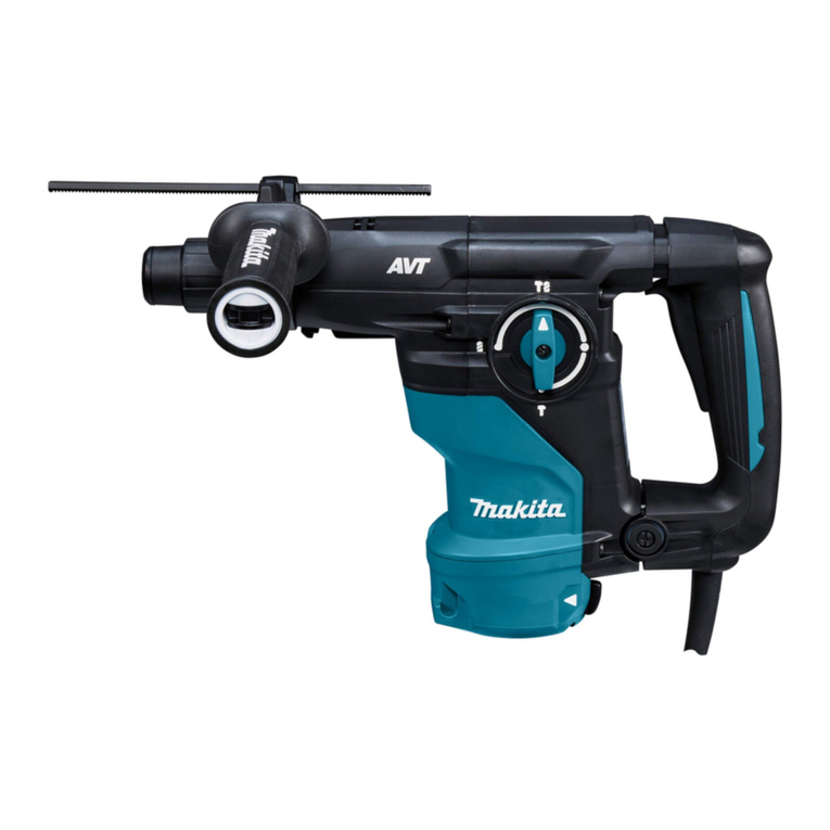
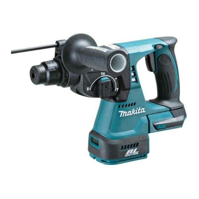
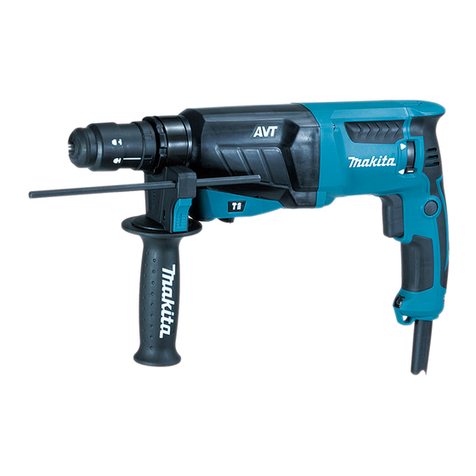
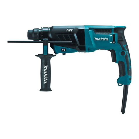
Makita HR2430 User manual

Rotary Hammer with Dust Extraction
25
mm
(1") MODEL
HR2430
25
mm
(1")
MODEL
HR2431
Variable Speed Variable Speed
INSTRUCTION MANUAL
Capacities
Concrete
Wood
DOUBLE
INSULATION
HR2431
Dust extraction capacities
Max.
drilling
depth Max.
bit
Max. bit Dust bag
IAdiustablede~thl diameter lenath caDacitv
SPECIFICATIONS
No
load
'peed
(RPM)
Overall length Net weight
BIOWS
per minute HR2430 HR2431
I
HR2430
I
HR2431
416
mm
477 mm 2,6 kg 2.8
kg
I
-
4'900
I
116-3/8"l
I
118-3/4"1
I
(5.7
lbsl
1
16.2
lbsl
0
-
1.050/min.
~
Manufacturer reserves the right to change specifications without notice.
Specifications may differ from country to country.
WARNING: For your personal safety, READ and UNDERSTAND before using.
SAVE THESE INSTRUCTIONS
FOR
FUTURE REFERENCE.

GENERAL SAFETY RULES
uSA002-1
(For
All
Tools)
WARNING! Read and understand
all
instructions.
Failure
tofollow all instructionslisted below,
may
result
in
electric
shock,
fire and/or serious personal injury.
SAVE THESE INSTRUCTIONS
Work Area
1.
Keep your work area cleanand well
lit.
Cluttered benchesanddark areas invite
accidents.
2.
Do
notoperatepowertools
in
explosiveatmospheres, suchas
in
the presence
of flammable liquids, gases, or dust. Power tools create sparks which may
ignite the dust or fumes.
3.
Keep bystanders. children, and visitors away while operating a power tool.
Distractions can cause you to lose control.
Electrical Safety
4.
DoubleInsulatedtools are equippedwithapolarizedplug(onebladeiswider
than the other.) This plug will
fit
in
a polarized outlet only one way.
If
the
plug does not fit fully
in
the outlet, reverse the plug.
If
it
still does not
fit,
contact a qualified electrician to install a polarized outlet.
Do
not change
the plug
in
any way. Double insulation
El
eliminates the need for the three
wire grounded power cord and grounded power supply system.
5.
Avoid body contact withgroundedsurfaces suchas pipes, radiators, ranges
and refrigerators. There is
an
increased risk of electric shock if your body is
grounded.
6.
Do
notexpose power tools torainor wet conditions. Water entering a power
tool will increase the risk of electric shock.
7.
Do
notabusethe cord. Never usethe cord to carry the tools or
pull
the plug
from anoutlet. Keepcord away from heat, oil, sharpedges or moving parts.
Replace damaged cords immediately. Damaged cords increase the risk of
electric shock.
8.
Whenoperating apower tooloutside, useanoutdoor extensioncord marked
“W-A”
or “W.” These cords are rated for outdoor use and reduce the risk
of electric shock.
PersonalSafety
9.
Stayalert, watchwhat youare doingandusecommon sense whenoperating
a power tool.
Do
not use tool while tired or under the influence of drugs,
alcohol, or medication.
A
moment
of
inattentionwhile operating power tools
may result
in
serious personal injury.
IO.
Dressproperly. Donot wear looseclothingorjewelry. Containlonghair. Keep
your hair, clothing, andglovesawayfrom moving parts. Looseclothes, jewelry
or long hair can be caught
in
moving parts.
2

11.
Avoid accidental starting. Be sure switch isoff before plugging in. Carrying
tools withyour finger on the switchor plugging intools that have the switch
on invites accidents.
12. Remove adjusting keys or wrenches before turning
the
tool on. A wrench
or
akey that isleft attached toarotatingpart
of
the tool may result
in
personal
injury.
13.
Do
notoverreach. Keep properfooting andbalanceatalltimes. Properfooting
and balance enables better control of the tool
in
unexpected situations.
14.
Use safety equipment. Always wear eye protection. Dust mask, non-skid
safety shoes, hard hat, or hearing protection must be used for appropriate
conditions.
Tool
Use and Care
15.
Use clamps or other practical way to secure and support the workpiece to
a stable platform. Holdingthe work by hand or against your body isunstable
and may lead to loss of control.
16.
Do
notforce tool. Usethe correct tool for your application. The correct tool
will do the job better and safer at the rate for which
it
is designed.
17.
Do
not use tool if switch does not turn
it
on or off. Any tool that cannot
be controlled
with
the switch is dangerous and must be repaired.
18.
Disconnectthe plugfrom the power sourcebeforemaking any adjustments,
changing accessories, or storing the tool. Such preventive safety measures
reduce the risk of starting the tool accidentally.
19.
Store idle tools out of reach of children and other untrained persons. Tools
are dangerous
in
the hands of untrained users.
20. Maintain tools with care. Keep cutting tools sharp and clean. Properly
maintained tools,
with
sharp cuttingedges are less likelytobind and are easier
to control.
21.
Check for misalignment or bindingof moving parts, breakage of parts, and
any other condition that may affect the tools operation.
If
damaged, have
the tool serviced before using. Many accidents are caused by poorly
maintained tools.
22.
Use only accessoriesthat are recommended by the manufacturer for your
model.Accessories that may be suitable for one tool, may become hazardous
when used on another tool.
SERVICE
23.
Tool
service must be performed only by qualified repair personnel. Service
or
maintenance performed by unqualified personnel could result
in
a risk of
injury.
24. When servicing a tool, use only identical replacement parts. Follow
instructions inthe Maintenance section of this manual. Use of unauthorized
parts
or
failuretofollow MaintenanceInstructionsmay create a riskof electric
shock or injury.
3

US6010-l
Specific
Safety
Rules
1.
Hold tools by insulated gripping surfaces when performing an operation
where the cutting tool may contact hidden wiring or its owncord. Contact
with
a “live” wire
will
make exposedmetalparts
of
the tool “live“ and shock
the operator.
2.
Wear ear protectors when using the tool for extended periods. Prolonged
exposure
to
high intensity noise can cause hearing
loss.
3.
Wear a hardhat (safety helmet), safety glassesand/or face shield.
It
isalso
highlyrecommended that you wear a dust mask and thickly paddedgloves.
4.
Be sure the bit is secured
in
place before operation.
5.
Under normaloperation, the toolisdesignedtoproducevibration.The screws
can come loose easily, causing
a
breakdown or accident. Check tightness
of screws carefully before operation.
6.
In
cold weather or when
the
tool has not been used for a long time, let the
tool warm up for a while by operating
it
under no load. This
will
loosen up
the lubrication. Without proper warm-up, hammering operation is difficult.
Be sure no one is below when using the tool
in
high locations.
7.
Always be sure you have a firm footing.
8.
Hold the tool firmly with both hands.
9.
Keep hands away from moving parts.
IO.
Do
not leave the
tool
running. Operate the tool only when hand-held.
11.
Do
not point the tool at any one
in
the area when operating. The
bit
could
12.
Do
not touch the
bit
or parts close tothe bit immediately after operation;
fly out and injure someone seriously.
they may be extremely hot and could burn your skin.
SAVE THESE INSTRUCTIONS.
4

SYMBOLS
The followings show the
symbols
used for tool.
v
................................
volts
A
................................
amperes
Hz
................................
herts
'L
................................
alternating current
n,
................................
no load speed
................................
Class
II
Construction
..&in
...............................
revolutions or reciprocation per minute
k
................................
number of blow
5

FUNCTIONALDESCRIPTION
Side
grip
(auxiliary handle)
The side grip swings aroundto either side,
allowing easy handling of the tool in any
position. Loosenthe side grip by turning it
counterclockwise, swing it to the desired
position and then tighten it by turning
clockwise.
Switchaction
CAUTION:
Beforeplugginginthe tool, alwayscheck to see that the switch trigger actuates properly
and returnsto the
"OFF"
positionwhen released.
To start the tool, simply pullthe trigger.
Tool
speed is increased
by
increasingpressureon
the trigger. Releasethe trigger
to
stop.
Reversingswitchaction
This tool has
a
reversingswitch to change
the direction of rotation. Move the lever to
the position (A position) for clockwise
rotation or the
+
position (B position) for
counterclockwise rotation.
I
Reversing
switch
lever
7
CAUTION
:
Always check the direction
of
rotationbefore operation.
Usethe reversingswitchonly after the tool comes to
a
completestop.Changing the direc-
Do
not pullthe switch trigger when the reversingswitch lever is inthe neutralposition.
tionof rotationbefore the toolstops may damage the tool.
If you pullthe trigger forcibly, the switch may be damaged.
6

Selectingthe action mode
I
This toolemploysan action modechanging
knob. Select one
of
the two modes suitable
for your work needs
by
usingthis knob.For
rotation only, turn the knob
so
that the
arrow on the knob points toward theam.
mark on the tool body. For rotation with
hammering, turn the knob
so
that the
arrow on the knob points toward the
mark on the tool body.
f
A\
,-
CSQ
\
$&I
Action
mode
changingknob
CAUTION:
Always set the knob fully to your desiredmode mark.
If
you
operate the
tool
with the knob
positionedhalf-way betweenthe mode marks, the tool may be damaged.
Torque limiter
The torque limiterwill actuatewhen
a
certaintorque level isreached.The motor will dis-
engage from the output shaft.When this happens, the bitwill stop turning.
CAUTION:
As soon
as
the torque limiter actuates, switch off the
tool
immediately.This will help pre-
vent prematurewear of the tool.
Holesaws, core bits, diamond core bits, etc. cannot be usedwith this tool. They tend
to
pinchor catcheasily inthe hole.This will cause the torque limiterto actuate too frequently.
ASSEMBLY
Installing
or
removingthe
drill
bit
CAUTION:
Always be sure that the tool is switched off and unplugged beforeinstallingor removingthe
bit.
Clean the bit shank and
grease (about
0.5
-
1
g)
before installingthe bit.
apply the bit
provided to it
7

Insertthe bit into the tool. Turn the bit and
push it inuntilit engages.
If
the bit cannot be pushedin, remove the
bit. Pullthe chuck cover down
a
couple of
times. Then insert the bitagain. Turn the bit
and push
it
inuntil itengages.
Bit
Chuck
cover
After installing,always make sure that the bit issecurelyheldin place
by
trying to pullit out.
To
removethe bit, pullthe chuck cover down
all
the way and pull the bit out.
Dust extractor attachment and dust bag
(inconcretedrilling operation)
With the dustextractor attachmentand the dust bag installedon this tool, you can do your
work very cleanlywithout dust scatteredaroundinthe work site.
CAUTION:
These two accessoriescan be usedonly for drilling holes inconcrete.Accordingly, do not
usethem in metalor wood drillingoperation.
8

Installing
dust
extractor attachment
Loosen the clamp screw of the side grip
by turning it counterclockwise. Insert the
coupling rod of the dust extractor attach-
ment through the coupling holeof the side
grip until the rod cannot be pushed in any
further. And the tighten the clamp screw
clockwise to secure the dust extractor at-
tachment. The couplingrodcan be inserted
from either side
A
or
B.
I
Clamp
screw
Coupli?g
hole
I
CAUTIO
N
:
At some angles of the side grip with the tool, the dust extractor attachment cannot be
installed on the tool because of the interference betweenthe attachment and the tool.
Insert firmly the hose
of
the dust extractor
attachment into the hose port of the tool
untilthe hose hitsagainstthe bottomof the
port to befixedfirmly to the tool.
Installing
dust
bag
Keepingthe angle of the dust bagwith the
tool
at
SO",
insert the dust baginto the dust
exhaust portof the tool. Secure the dust bag
by turning
it
clockwise.
r--
Hose
Dustexhaust port
1
9

Adjustingthe position
of
dust extractor
I
attachment
Loosen the clamp screw
of
the dust ex-
tractor attachment
by
turning it counter-
clockwise.
And then align the tip
of
the bit with the
top
of
the dust extractor attachment.
Tighten the clamp screw
by
turning it
clockwise to secure the dust extractor
attachment.
Clamp
screw
-/
I
Depth adjustment
Loosen the screw
of
the stopperby turning
it counterclockwise
so
that the stopper
could slide on the depth gauge
of
the dust
extractor attachment. Slide the stopper to
the desireddrilling depth
of
the gauge, and
then tighten the screw
by
turning
it
clock-
wise.
Stopper
-
10

Drillingin
wood
or
metal
Use the optional drill chuck assembly
(consistingof drill chuck and chuck adapter
assembly). When installing it, refer to
"installingor removing drill bit" described on
the previous page. Set the action mode
changing knob to "rotationonly".You can drill
up to 13 mm (1/2")diameter inmetaland up
to 32 mm (1-1/4")diameter inwood.
CAUTION:
Never use "rotationwith hammering"when the drill chuck assembly is installedon the tool.
The drill chuck assembly may be damaged. Also, the drill chuck will come off when revers-
ingthe tool.
NOTE:
If you needassemblethe drill chuck and chuck adapter assembly, proceedas follows.
Secure the drill chuck in
a
vise or similar
securingdevise. Place the chuck key inone
of
the three holes
so
that the chuck body
will not turn.
Wrench
7
/
Remove the screw from the chuck adapter assembly and screw the chuck adapter
into the drill chuck. Use
a
wrench to tighten the chuck adapter securely, applying about
29 N.m
-
39 N.m(22
-
29 ft .Ibs)torque. [Note:you can obtain 29 N'm
-
39
N.m (22
-
29 ft 'Ibs)torque by applyingpressure
of
30
-
40
kg
(66
-
88
Ibs)to the wrench while hold-
ingthe portion 10cm
(4")
from the wrench head.]
Open the
chuck
jaws
fully
and insert the
screw through the chuck opening. Tighten
the screw counterclockwise with
a
screw-
driver.
T-
-
I
L-
screw
11

OPERATION
Drilling with dust extractorattachment
Indrillingoperation, holdthe tool
so
that the
top end of the dust extractor attachment
is
always kept in complete contact with the
surface of concrete.
CAUTION:
Any space betweenthem would result in
a
considerable
loss
of dust extracting power.
Cleaning out dust bag
Remove the dust bag from the tool.
Pull the fastener out of the dust bag, and
then remove dust
or
particles to clean out
the dust bag.
7
Fastener
CAUTION:
Too much dust inthe dust bagwould result in
a
considerable
loss
of dust extractingpower.
Accordingly, cleanout the dust bag from time to time.
Drillingwithout dust extractor
attachment
This tool can be also used as
a
standard
rotary hammer without the dust extractor
attachmentand the dust bag.
Dustexhaustport
Beforedrillingoperationwithout the dust extractor attachment and the dust bag, plugthe
hose port with the cap provided.
The cap reducesthe exhaust air fromthe dust exhaust port for your comfortableoperation.
12

Hammer drillingoperation
Positionthe bit at the desiredlocation
for
the hole, then pullthe trigger.
Do
notforce the
tool. Light pressure gives best results. Keep the tool in positionand prevent itfrom slipping
away from the hole.
Do
not apply more pressure when the hole becomescloggedwith
chipsor particles.Instead, runthe tool at an idle,then remove the bitpartiallyfrom the hole.
By
repeatingthis several times, the hole will be cleaned out and normaldrilling may be
resumed.
CAUTION:
There is
a
tremendousand sudden twistingforce exertedon the tool/bit at the time
of
hole
breakthrough,when the hole becomescloggedwith chipsand particles, or when striking
reinforcingrods embeddedinthe concrete.Always use the side grip (auxiliawhandle)and
firmly holdthe tool by bothside grip and switch handle duringoperations.Failureto do
so
may result inthe
loss
of
control
of
the tooland potentially severe injury.
Blow-outbulb
Use the optional blow-out bulb to clean
out the hole.
\
13

MAINTENANCE
CAUTION:
Always be sure that the tool
is
switchedoff and unpluggedbeforeattemptingto perform
inspectionor maintenance.
To
maintainproduct SAFETY and RELIABILITY,repairs, carbon brush inspectionand replace-
ment, any other maintenance or adjustment should be performedby MakitaAuthorizedor
FactoryServiceCenters, always using Makitareplacement parts.
14

ACCESSORIES
CAUTION:
These accessories or attachments are recommended for use with your Makita tool specified inthis
manual.The use
of
any other accessories or attachmentsmight present
a
risk
of
injury topersons. The
accessories or attachments should be used only inthe proper and intendedmanner.
Diameter
..
.
5/16'
5/16'
318"
711
6"
711
6'
7/16'
1
E"
1
E.
1/2"
1/2"
9/16'
9/16"
9/16"
510"
5m"
5/8"
11/16"
3113-
3113-
5m-
SDS PlusCarbide-tippedbits
-
Overalllength
4'
Part
No.
7
1
1140A
711141-A
711142-A
711
1
43-A
711144-A
711146-A
71
1
i46-A
711147-A
711148-A
711149-A
711150-A
711151-A
..
.
. ..
.
71
1
152-A
711153-A
711155-A
71
1
156-A
71
11
57-A
711156-A
711159-A
..
.
.
.
.
.
.
711160-A
711161-A
711162-A
7
1
1163-A
711164-A
711186-A
711168-A
71
1
167-A
711168-A
711169-A
71
1
170-A
711171.6
..
.
.
.
.
..
71
1
172-A
71
11
73-A
711174-A
711175-A
71
11
76-A
71
11
77-A
71
1
176-A
5/32'
5/32"
3/16"
3/16"
3/16"
3/16'
3/18.
11.4'
114"
114-
114"
114"
6"
4"
6"
6"
12"
14"
4"
6"
8"
10"
14"
6'
12"
6'
12"
24"
6"
12-
16"
6"
12"
18"
24'
6'
12"
18"
6'
12"
18'
24"
8.
Bit grease
100
g;
3.5
02.
Part
No.
181573-3
Safety goggles
Gray lens: Part No. 191684-A
Clean lens Part
No.
191685-A
Chuck key
513
Part No. 763432-9
Drill chuck
S13
Part
No.
763047-2
t
Chuck adapter assembly
Part
No.
122573-4
Blow-out bulb
Part
No.
765009-6
Cap
Part No. 421727-3
Plastic case
Part
No.
024575-3
15

MODEL
HR2430
16

ITEMNO. DESCRIPTION
CAP
31
I
2
3
4
5
E
7
8
9
10
II
12
13
I4
15
16
17
I8
19
20
21
22
23
24
25
26
27
28
29
30
31
32
33
34
35
36
37
36
39
40
41
42
CIO
c20
C30
43
44
45
46
47
48
49
50
51
52
53
54
55
56
CHUCKCOVER
COMPRESSIONSPRING
36
RINGSPRING
17
RING SPRING
30.5
SWING GUIDE
COMPRESSIONSPRING
35
LEAFSPRINO
26
AN
8
CHUCK RING
STEELBALL
7.0
GUlOE WASHER
SOUARE BOLT
M8X6O
SOUAREWASHER
9
BELT
OIL SEAL
20
GRIP BASE
GRIP
36
COMPLETE
HEX
NUTM5
FLAT WASHER
5
SCREW
M5X20
HEX.
NUT
ME
PIPEHOLDER
STOPPER RING
SEALINGCAP
40
FLAT WASHER
6
THUMB SCREW
M6X30
THUMB SCREW
M4X24
TAPPING SCREW
4x16
COLLECTOR25L
COLLECTOR
25R
MAKITALABEL
FLAT WASHER
28
FlmNGRUBBER
SUPPORTPIPE
SLIDEPIPE
COMPRESSIONSPRING
25
SPRING STOPPER
HOSE
19
CUFFS 19-22
TAPPINGSCREW
4x90
GEAR HOUSlNaCOMPLETE
STEELBALL
5.6
COMPRESSIONSPRING
3.5
INDICATIONLABEL
BALLBEARIN0 6904LLU
RINGSPRING
26
FLAT WASHER
29
COMPRESSIONSPRING
29
SPUR
GEAR
48
STEEL BALL
5.6
TOOL HOLDER
FLAT WASHER 27
0
RING
10
IMPACTBOLT
0
RING
I
I
STRIKER
0
RING
I6
PIN
6
NO. USED ITEMNO. DESCRIPTION
57 PISTONCYLINDER
I
I
I
I
I
I
I
I
I
I
I
I
I
I
I
1
I
I
I
I
I
I
I
I
1
I
I
I
I
I
I
1
I
I
I
I
I
I
I
I
4
I
I
I
I
I
I
I
I
I
4
I
I
I
I
I
I
I
I
58
59
60
E1
E2
63
64
65
66
67
68
69
70
71
72
73
74
75
76
77
78
79
60
81
82
63
84
65
86
87
88
89
90
91
92
93
94
95
96
97
96
99
IO0
101
CIO
102
I03
I05
IO6
107
108
109
110
Ill
I12
I
I3
I
I4
I
I5
I
I6
NEEDLE BEARING
810
CONNECTINGROD
CRANKSHAFT
BALLBEARING
69922
FLATWASHER
9
BALLBEARING
&I922
CRANK HOUSING COMPLETE
THRUST
NEEOLEBEARING
1224
STRAIGHTBEVELGEAR
12
GEAR COVER
PANHEAD SCREW
M4XI6
PANHEAD SCREW
MIX50
HELICALGEAR
3
I
COMPRESSION SPRING
8
STRAIGHTBEVELGEAR
I4
FLATWASHER
8
CLUTCHCAM
COMPRESSION SPRING
12
FLAT WASHER
12
SPUR
WAR
IO
BALL BEARING
W6Z2
0
RING I7
CHANGE LEVER COMPLETE
+PANHEADSCREW
MI
0
RING 67
INNER
HWSING
COMPLETE
0
RING
24
BALL BEARINGEOSLLU
DUSTGUARD
RETAININGRING
S-IO
FANHOUSING
DUSTPROOFWEET
PLATF
-.
-
FAN
56
DUSTCOVER
FLAT WASHER
10
BALL BEARINGQOOLLU
FLATWASHER
10
FAN
€4
ARMATURE ASSEMBLY
INSULATIONWASHER
BALL BEARINGQ7LLB
FLATWASHER
14
DUSTBAO ASS'Y
FASTENER
MOTOR
HOUSING
NAME PLATE
HRZUO
BAFFLEPLATE
TAPPINGSCREW
4x60
CARBONBRUSH
BRUSH
HOLDER
HANDLECOVER
TAPPINGSCREW
4x20
SITCHLEVER
SITCH
TAPPINGSCREW
4x18
STRAINRELIEF
CORDGUARD
NO.
USED
I
I
I
1
I
I
I
I
I
I
I
2
3
I
1
I
I
I
I
I
I
I
I
I
I
I
I
I
1
1
I
I
I
I
I
I
I
I
I
I
I
I
I
I
I
I
I
1
I
2
2
2
I
4
I
I
2
1
I
I
17

18

ITEMNO. DESCRIPTION
I
2
3
4
5
6
1
8
9
10
II
12
13
I4
15
16
I7
18
19
20
21
22
23
24
25
26
21
28
29
30
31
32
33
31
35
35
37
36
39
40
41
42
c10
,220
C30
43
44
45
45
41
48
49
50
51
52
53
54
55
58
._..
CAP
31
CHUCKCOVER
COMPRESSIONSPRING
36
RING SPRING
11
RING SPRING
30
5
SPRING GUIDE
COMPRESSIONSPRING
35
LEAFSPRING 26
PIN
8
CHUCK RING
STEELBALL
7
0
GUIDEWASHER
SGUARE BOLT
Max60
SGUARE WASHER
9
BELT
OIL SEAL 20
GRIP BASE
GRIP
36 COMPLETE
HEX.
NUT
~5
FLAT WASHER
5
SCREW
M5XZO
HEX. NUT
M5
PIPEHOLOER
STOPPER
RIM
SEALINGCAP
40
FLATWASHERB
THUMB SCREW
M6X30
lHUMB
SCREW
M4X24
TAPPINOSCREW 4x16
COLLECTOR25L
COLLECTOR
25R
MAKITA LABEL
FLATWASHER
28
FlmNGRUBBER
SUPPORTPIPE
SLIDEPIPE
COMPRESSIONSPRINO
25
SPRING STOPPER
HOSE I9
CUFFS 19-22
TAPPINO SCREW
4x90
OEAR
nousiNa
COMPLETE
STEELBALL
5.6
COMPRESSIONSPRING
3.5
INDICATIONLABEL
BALLBEARIND 6904LLU
RING SPRING 26
FLATWASHER 29
COMPRESSION SPRING 29
SPUR GEAR
46
STEELBALL
5.6
TOOL HOLDER
FLAT WASHER
21
0
RINO
IO
IMPACTBOLT
0
RING
I
I
STRIKER
0
RING
I6
PIN
6
NO. USED
ITEM
NO DESCRIPllON
I
I
I
I
I
I
I
I
I
I
I
I
I
I
I
I
I
1
t
I
I
I
I
I
I
1
1
I
I
1
I
I
I
I
I
I
I
I
1
1
4
I
I
I
I
I
I
I
I
I
4
I
I
1
I
I
I
I
I
58
59
60
01
62
53
64
85
65
61
68
59
10
71
72
13
14
15
16
17
1.9
79
80
81
82
83
84
85
86
87
85
89
90
91
92
93
94
95
95
97
95
99
100
101
c10
IO2
103
105
I00
107
105
109
I10
Ill
112
1
I3
I
I4
1
I5
I16
_..
57
PISTONCYLINDER
NEEDLEBEARING
610
CONNECTING ROD
CRANKSHAFT
BALL BEARING69922
FLATWASHER
9
BALLBEARING68922
CRANK
HousiNa
COMWETE
MUST
NEEDLE
BEARING 1224
STRAIGHTBEVELGEAR
12
OEAR COVER
PANHEAD SCREW
M4XI5
PANHEAD SCREW
MIX50
HELICAL
GEAR
31
COMPRESSION SPRING
8
STRAIGHTBEVELGEAR
I4
FLATWASHER
8
CLUTCHCAM
COMPRESSIONSPRING 12
FLATWASHER
12
SPUR GEAR
10
BALLBEARINGA522
0
RING
11
CMNGELEVER COMPLETE
0
RING 07
INNER HOUSING COMPLETE
+PANHEAD
SCREW
~4
0
RING
24
BALL BEARING609LLU
DUSTGUAR0
RETAININORING
S-IO
FANHOUSING
DUSTPROOFSHEET
PLATE
FAN
56
DUSTCOVER
FLATWASHER
10
BALL BEARINGAOOLLU
FLATWASHER
IO
FAN
A
ARMATUREASSEMBLY
INSUllGNWASHER
BALLBEARINGA7LLB
FLATWASHER
I4
DUSTBAG ASS'Y
FASTENER
MOTOR HOUSING
NAME PLATE
HRZUO
BAFFLEPLATE
TAPPINGSCREW
4x00
CARBONERUSH
BRUSHHOLDER
HANDLECOVER
TAF'PINO SCR€W
4x20
SWITCH LEVER
SWITCH
TAPPINGSCREW
4x18
STRAINRELIEF
CORD GUARD
CORD
NO. USED
I
I
I
I
I
I
I
I
I
I
I
2
3
I
I
1
I
I
1
t
I
I
I
I
I
I
1
I
I
I
I
I
I
I
I
I
I
I
I
I
I
I
I
I
I
I
I
1
1
2
2
2
I
4
I
I
2
I
I
I
19

MAKITA
LIMITED
ONE
YEARWARRANTY
Warranty
Policy
Every Makita tool is thorou ly inspected and tested before leaving the factory. It is warranted to
be free of defects from workanshi and materials for the period of ONE YEAR from the date of
original urchase. Should any troubE develop during this one-year period, return the COMPLETE
tool, frebtprepaid, toone of Makita’s Factory or Authorized ServiceCenters. If inspection shows
the trouble is caused by defective workmanship or material, Makita will repair
(or
at our option,
replace) without charge.
ThisWarranty doesnot apply where:
repairshave been made or attempted by others:
repairsarc required kcaum
of
normal wear and tear:
e
The tool has been abused, misused or improperly maintained:
alterations have been made tothe tool
IN NO EVENT SHALL MAKITA BE LIABLE FOR ANY INDIRECT, INCIDENTAL OR CON-
SEQUENTIALDAMAGES FROM THE SALE
OR
USE OFTHE PRODUCT. THIS DISCLAIMER
APPLIESBOTH DURING AND AnERTHETERM
OF
THISWARRANTY.
MAKITA DISCLAIMS LIABILITY FOR ANY IMPLIED WARRANTIES, INCLUDING IMPLIED
WARRANTIES
OF
“MERCHANTABILITY” AND “FITNESS
FOR
A SPECIFIC PURPOSE.”
AFTER THEONE-YEAR TERM OFTHIS WARRANTY.
This Warranty gives you specific legal rights, and you may also have other rights which vary from
state to state. Some states do not allow the exclusion or limitation of incidental or consequential
damages,
so
the
above
limitation or exclusion may not apply to you. Some states do not allow
Makita Corporation
3-11
-8,
Sumiyoshi-cho,
Anjo, Aichi
446-8502
Japan
884313-067
PRINTED
IN
JAPAN
2000
-
8
-
N
Other manuals for HR2430
4
This manual suits for next models
1
Table of contents
Other Makita Tools manuals

Makita
Makita HR008G User manual

Makita
Makita BHR202 User manual

Makita
Makita HR3541 User manual

Makita
Makita M8600 User manual

Makita
Makita HM1511 User manual

Makita
Makita DTM52 User manual

Makita
Makita MW001G User manual

Makita
Makita DTM40 User manual

Makita
Makita DGP180 User manual

Makita
Makita 3706 User manual

Makita
Makita M1902 User manual

Makita
Makita HR2650 User manual

Makita
Makita BHR162 User manual

Makita
Makita HR2631F User manual

Makita
Makita HR2631FTJ User manual

Makita
Makita DCX200 User manual

Makita
Makita BHR242 User manual

Makita
Makita BUX360 User manual

Makita
Makita DG002G User manual

Makita
Makita HR2300 User manual