10
Dust cup (optional accessory)
Fig.22
Use the dust cup to prevent dust from falling over the
tool and on yourself when performing overhead drilling
operations. Attach the dust cup to the bit as shown in
the figure. The size of bits which the dust cup can be
attached to is as follows.
Bit diameter
Dust cup 5 6 mm - 14.5 mm
Dust cup 9 12 mm - 16 mm
006406
There is another type of dust cup (optional accessory)
which helps you prevent dust from falling over the tool
and on yourself when performing overhead drilling
operations.
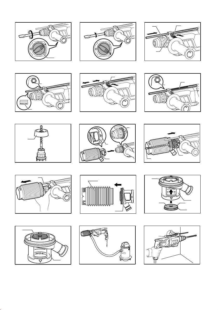
Installing or removing the dust cup
(optional accessory)
Fig.23
Before installing the dust cup, remove the bit from the
tool if installed on the tool. Install the dust cup (optional
accessory) on the tool so that the symbol on the
dust cup is aligned with the grooves in the tool.
Fig.24
To remove the dust cup, pull the chuck cover in the
direction as shown in the figure and with the chuck
cover pulled take the bit out of the tool.
Fig.25
And then grab the attachment at the foot of dust cup
and take it out.
Fig.26
Fig.27
Fig.28
NOTE:
•
When installing or removing the dust cup, the cap
may come off the dust cup. At that time, proceed as
follows. Remove the bellows from the attachment
and fit the cap from the side shown in the figure with
its flat side facing upward so that the groove in the
cap fits in the inside periphery of the attachment.
Finally, mount the bellows that has been removed.
Fig.29
NOTE:
• If you connect a vacuum cleaner to your hammer,
cleaner operations can be performed. Dust cap
needs to be removed from the dust cup before the
connection.
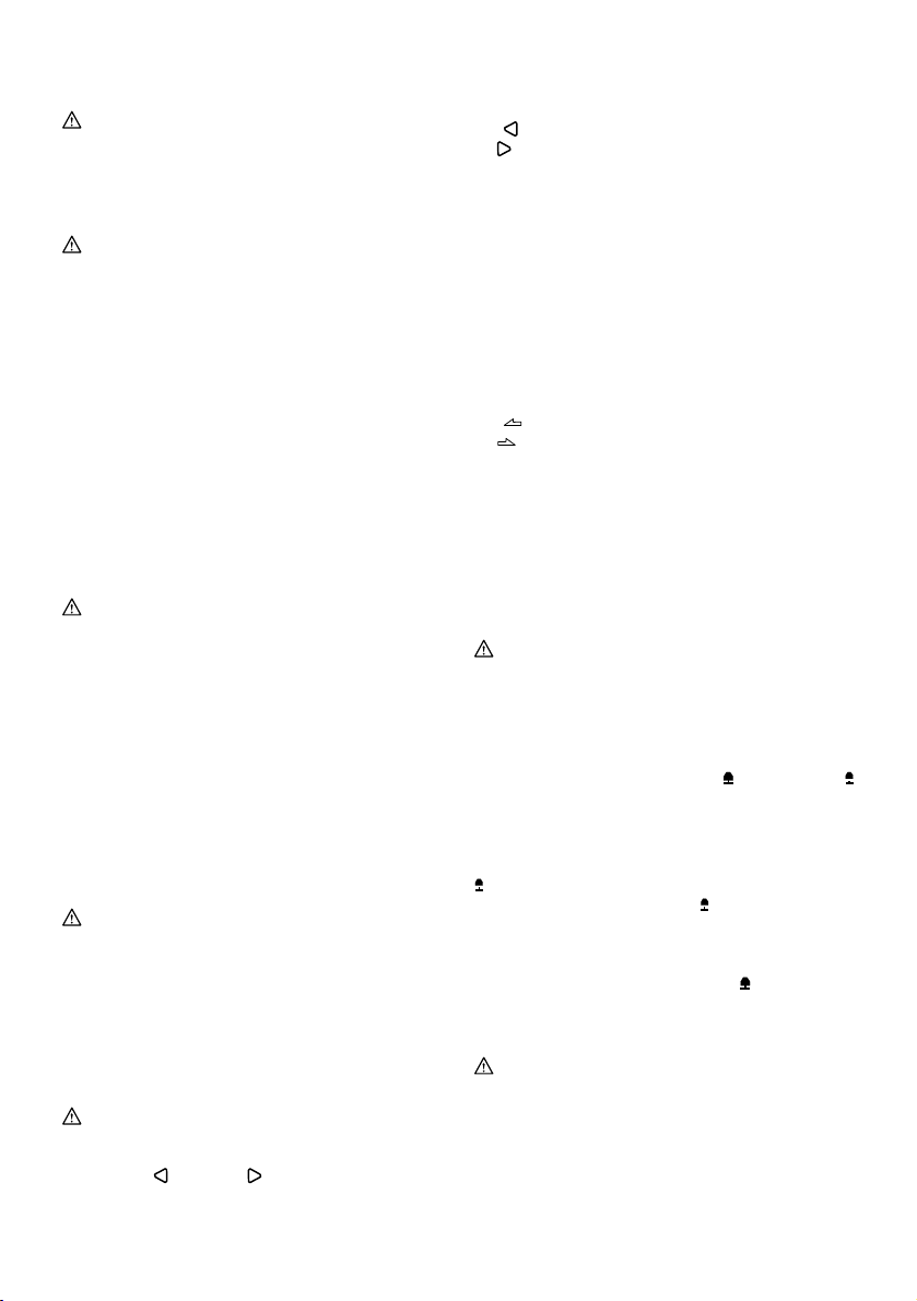
OPERATION
CAUTION:
• Always use the side grip (auxiliary handle) and
firmly hold the tool by both side grip and switch
handle during operations.
Hammer drilling operation
CAUTION:
•
There is a tremendous and sudden twisting force
exerted on the tool/bit at the time of hole break-through,
when the hole becomes clogged with chips and particles,
or when striking reinforcing rods embedded in the
concrete. Always use the side grip (auxiliary handle) and
firmly hold the tool by both side grip and switch handle
during operations. Failure to do so may result in the loss
of control of the tool and potentially severe injury.
Fig.30
Set the action mode changing knob to the symbol.
Position the bit at the desired location for the hole, then
pull the switch trigger. Do not force the tool. Light
pressure gives best results. Keep the tool in position
and prevent it from slipping away from the hole.
Do not apply more pressure when the hole becomes
clogged with chips or particles. Instead, run the tool at
an idle, then remove the bit partially from the hole. By
repeating this several times, the hole will be cleaned out
and normal drilling may be resumed.
NOTE:
Eccentricity in the bit rotation may occur while operating
the tool with no load. The tool automatically centers itself
during operation. This does not affect the drilling precision.
Blow-out bulb (optional accessory)
Fig.31
After drilling the hole, use the blow-out bulb to clean the
dust out of the hole.
Chipping/Scaling/Demolition
Fig.32
Set the action mode changing knob to the symbol.
Hold the tool firmly with both hands. Turn the tool on
and apply slight pressure on the tool so that the tool will
not bounce around, uncontrolled. Pressing very hard on
the tool will not increase the efficiency.
Drilling in wood or metal
CAUTION:
•
Never use "rotation with hammering" when the
quick change drill chuck is installed on the tool.
The quick change drill chuck may be damaged.
Also, the drill chuck will come off when reversing the tool.
•
Pressing excessively on the tool will not speed up the
drilling. In fact, this excessive pressure will only serve
to damage the tip of your bit, decrease the tool
performance and shorten the service life of the tool.
• There is a tremendous twisting force exerted on
the tool/bit at the time of hole breakthrough. Hold
the tool firmly and exert care when the bit begins
to break through the workpiece.
• A stuck bit can be removed simply by setting the
reversing switch to reverse rotation in order to