manuals.online logo
Brands
  1. Home
  2. •
  3. Brands
  4. •
  5. KYOWA
  6. •
  7. Transducer
  8. •
  9. KYOWA DTC-A User manual

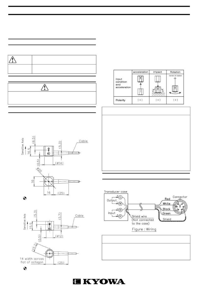
KYOWA DTC-A User manual

IM-T-221B May,2018
DTC-A Clip-type Displacement Transducer INSTRUCTION MANUAL
Thank you for purchasing this KYOWA product. Before using it,
read this instruction manual carefully. Also, keep the manual within
easy reach so that you can refer to it whenever necessary.
1.
Calling the operator’s attention
Be sure to observe the accompanying precautions preserve the
performance of the instrument.
Caution
It is a precaution to operate properly.
2.
Handling precautions
Caution
Do not
expand the space between the two beams or narrow it
even after they get in touch with the stoppers.
This product is exclusively designed for indoor use. When using
it, take care to avoid the direct rays of the sun, water, oil and
solvent.
Avoid measurement under vibration or impact.
Do not disassemble the displacement transducer.
3.
Installation
The mounting sections of the transducer (the respective heads of
the two beams) are so designed that they confirm with the ASTM
(American Society for Testing & Materials) Standards E399. Use
the transducer properly by referring to the standards.
3.1
How to mount
On the measuring area, prepare two opposed grooves to
accept the transducer, or mount the transducer by screwing or
bonding two opposed tips (TIP-10A) (available as options) to
the transducer mounting section.(See Fig.3.1.1 and 3.1.2)
Fig.3.1.1 Configuration of groove on measuring object (ASTM Std.)
Fig.3.1.2 Configuration of tip (TIP-10A) (option)
When the two beams are free, the space between them is about
11mm. The measuring range is denoted by the space between the
mounting grooves. It is 4 to 9mm on DTC-A-5 and 8 to 10mm on
DTC-A-2. Fix the cable nearby the mainframe so that the mass of
the cable will not affect the transducer.
4.
Connection and measurement
4.1
Connect the transducer to a strain amplifier.
4.2
Perform connection as illustrated below when using an NDIS
connector.
Displacement transducer
(The shield wire is not connected to the mainframe.)
4.3
It is required to heat-run for 5 to 10 minutes before starting the
measurement.
4.4
Measurement values increase in the PLUS direction as space
grows between the beams.
5.
Conversion
5.1
Use the calibration constant described in the test data sheet to
convent a reading into a displacement value.
5.2
When a strain amplifier is in use, output reads in μm/m
equivalent strain (×10
-6
equivalent strain). Find a displacement
value corresponding to μm/m. Then, obtain a displacement
value through multiplication using the following equation.
Displacement value(mm)
=Strain amplifier's output (μm/m)
×Calibration constant (mm/1μm/m)
5.3
When using an amplifier of other type or a recorder, first find
the exact bridge exciting voltage applied. Second, find the
displacement value that corresponds to 1(μV) output voltage
against 1(V) bridge excitation voltage. Then, obtain the
displacement value through multiplication using the following
equation.
Displacement value(mm)
=
Bridge output voltage(μV)
×Calibration constant (mm/1μV/V)
Bridge excitation voltage(V)
6.
Storage and inspection
6.1
Avoid water, oil and dust on the displacement transducer.
6.2
If an abnormal initial value or reading appears, measure input
resistance, output resistance as well as insulation resistance
(which should be 100M or higher) between the main body
and red to green.
If abnormal resistance is found, the cause may be failure of the
sensing element. In this case, contact your KYOWA
representative for necessary inspection.
Caution
To measure insulation resistance, apply a voltage lower than
50V to the insulation resistance tester.
When storing the transducer, be sure that it is free from
displacement.
Avoid storing the transducer where it is exposed to especially
high or low temperature or much dust.
URL http://www.kyowa-ei.com/
7.
Dimensional drawing
Fig.7.1 DTC-A-2
Fig.7.2 DTC-A-5
8.
Specifications
Models
Rated Capacity (Bezel Distance)
Measuring Force
(Approx.)
Natural Frequencies
(Approx.)
DTC
-
A
-
2
2mm (8 to 10mm)
4 to 20N
580Hz
DTC
-
A
-
5
5mm (4 to 9mm)
1 to 10N
215Hz
◆
Performance
Rated Capacity See table below.
Nonlinearity Within ±1%RO
Hysteresis Within ±1%RO
Repeatability 1%RO or less
Rated Output 2.5 mV/V (5000 μm/m)
◆
Environmental Characteristics
Safe Temperature -10 to 60
℃
Compensated
Temperature 0 to 50
℃
Temperature Effect
on Zero Within±0.05%RO/
℃
Temperature Effect
on Output Within±0.05%/
℃
◆
Electrical Characteristics
Safe Excitation 10V AC or DC
Recommended Excitation 2 to 4V AC or DC
Input Resistance 350 ±2%
Output Resistance 350 ±2%
Cable 4-conductor (0.08mm
2
) vinyl
shielded cable, 3.2mm diameter by
2m long, bared at the tip
(Shield wire is not connected to the
case.)
◆
Mechanical Properties
Safe Overload Rating 130% (With a stopper)
Natural Frequencies See table below.
Measuring Force See table below.
Weight Approx. 20g (Excluding cable)
◆
Accessories
Test Data Sheet 1
Instruction manual 1 (This book)
+20%
-10%
IM-T-221B 2018.5
DTC-A型 クリップ型変位変換器-取扱説明書
このたびは本製品をお買い上げいただきまして,ありがとう
ございます。ご使用の前には,本書を必ずお読みください。
また,お読みになったあとはいつでも見られるところに必ず
保管してください。
1.
取扱説明書中のマークについて
機能確保に関する事項にはマークをつけて記載していますの
で,必ずお読みください。
注意
正しく動作させるための注意です。
2.
使用上のご注意
注意
2枚のビームを広げたり,ストッパに当たってからも狭め
ようとしたりしないでください。
本製品は屋内使用向けです。直射日光の当たる場所や水,
油,溶剤等のかかる場所は避けてください。
振動や衝撃下での測定は避けてください。
変換器を分解しないでください。
3.
取り付け
本製品の取り付け部(2枚のビームの先端部)は米国の材料
試験規格 ASTM E399 に合わせてあります。この規格を参考に
ご使用ください。
3.1
取り付け方法
測定しようとするところに本製品を取り付けるための溝
を2個対向させて加工するか,オプション(別売)部品
のチップ(TIP-10A)を2個対向させてネジ止めまたは接
着にて取り付けます。(図 3.1.1~図 3.1.2 参照)
図 3.1.1 被測定部の溝形状(ASTM 規格)
図 3.1.2 チップ(TIP-10A)形状(オプション)
2枚のビームの取付溝間隔は自由な状態で約 11mm となって
います。測定範囲は DTC-A-5 が取付溝間隔 4~9mm,DTC-A-2
が取付溝間隔 8~10mm です。
ケーブルの質量が変換器本体に作用しないように本体の近く
でケーブルを固定してください。
4.
接続・測定
4.1
変換器をひずみ測定器に接続します。
4.2
NDIS 規格品のコネクタを用いる場合は,次のように接続
します。
(変換器本体にはシールド線は接続されていません)
4.3
5~10 分のヒートランを行ってから測定を開始してくだ
さい。
4.4
測定値はビームの間隔が開くとプラス方向に増加します。
5.
換算
5.1
変位の換算には検査成績書の校正係数を用います。
5.2
ひずみ測定器を使用する場合は,出力がε(×10
-6
ひず
み)で表示されます。1(×10
-6
ひずみ)に相当する変位が
検査成績書に記入されていますので,乗算により変位量
が求められます。
求める変位量(mm)
=[ひずみ測定器の出力ε(×10
-6
ひずみ)]
× [校正係数(mm/1×10
-6
ひずみ)]
5.3
その他の増幅器,記録器を使用する場合はブリッジ印加
電圧を正確に計ることが必要になります。検査成績書に
はブリッジ印加電圧1(V)を加えたときの出力電圧 1(μ
V)に相当する変位が記入されていますので乗算により変
位量が求められます。
求める変位量(mm)
=
ブリッジ出力電圧(μV)
×校正係数(mm/1μV/V)
ブリッジ印加電圧(V)
6.
保管上の注意および点検
6.1
変位変換器には水,油,塵などがつかないようにしてく
ださい。
6.2
初期値,指示値が異常と思われる場合は,入力抵抗,出
力抵抗,本体とケーブル心線間の絶縁抵抗(100MΩ以上)
を測定してください。
異常があれば本器の故障と考えられます。弊社の営業ま
でご連絡ください。
注意
絶縁抵抗を測定する場合には,絶縁抵抗計の印加電圧は
50V 以下でご使用ください。
保管時は変位を与えないで保管してください。
特に湿度の高いところや低いところ,湿度の高いところや
塵埃の多いところでの保管は避けてください。
変位変換器
http://www.kyowa-ei.com/
7.
外形寸法図
図 7.1 DTC-A-2 図 7.2 DTC-A-5
8.
仕様
型式名 定格容量 測定力(約)
固有振動数(約)
DTC-A-2 2mm(取付溝間隔 8~10mm 範囲)
4~20N 580Hz
DTC-A-5 5mm(取付溝間隔 4~9mm 範囲)
1~10N 215Hz
◆性能
定格容量 :表参照
非直線性 :±1%RO 以内
ヒステリシス :±1%RO 以内
繰り返し性 :1%RO 以下
定格出力 :2.5mV/V(5000×10
-6
ひずみ)
◆環境特性
許容温度範囲 :-10~60℃
温度補償範囲 :0~50℃
零点の温度影響 :±0.05%RO/℃以内
出力の温度影響 :±0.05%/℃以内
◆電気的特性
許容印加電圧 :10V AC または DC
推奨印加電圧 :2~4V AC または DC
入力抵抗 :350Ω±2%
出力抵抗 :350Ω±2%
ケーブル :0.08mm
2
,4 心シールドビニル 2m
外径 3.2mm,先端むき出し
(シールドは本体に接続されてい
ません)
◆機械的特性
許容過負荷 :130%(ストッパ付)
固有振動数 :表参照
測定力 :表参照
質量 :約 20g(ケーブル含まず)
◆付属品
検査成績書 :1部
取扱説明書(本書) :1部
+20%
-10%

This manual suits for next models

2

Other KYOWA Transducer manuals

KYOWA DTH-A User manual

KYOWA

KYOWA DTH-A User manual

KYOWA DTPA-A-5K User manual

KYOWA

KYOWA DTPA-A-5K User manual

KYOWA PG-2KU User manual

KYOWA

KYOWA PG-2KU User manual

KYOWA ASH-A-10 User manual

KYOWA

KYOWA ASH-A-10 User manual

KYOWA BER-A-15S User manual

KYOWA

KYOWA BER-A-15S User manual

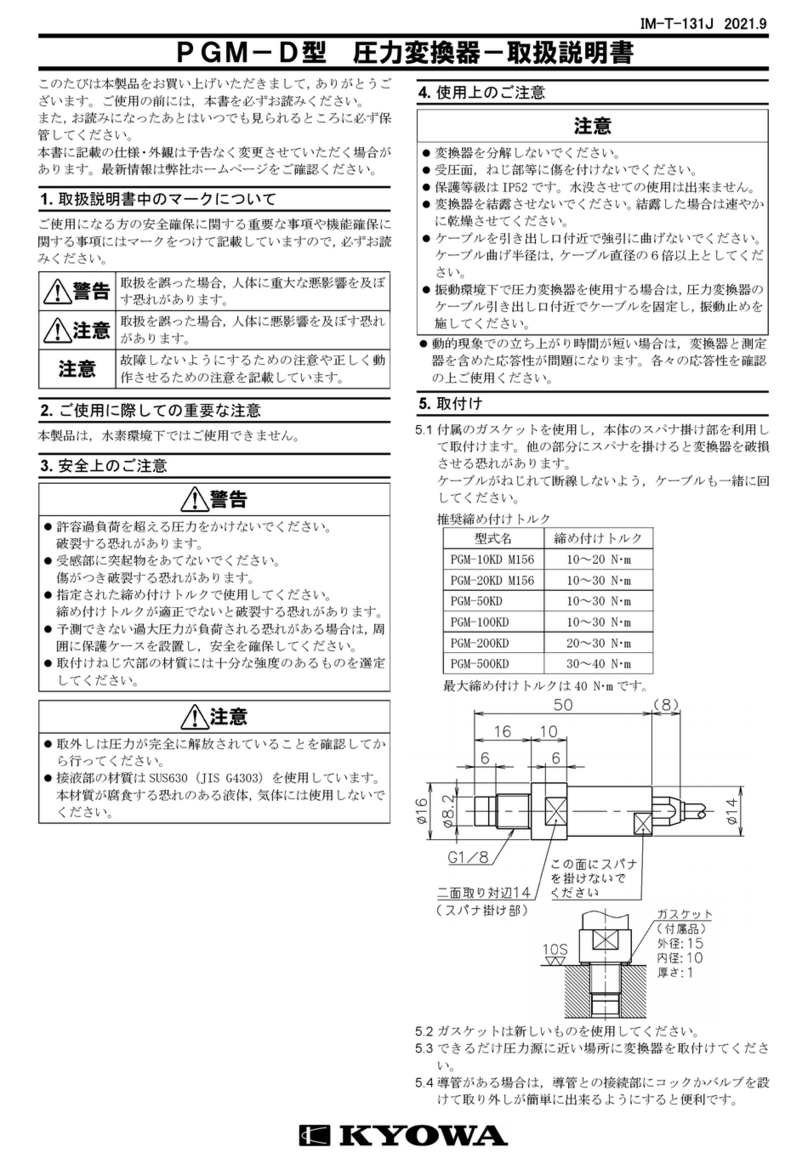
KYOWA PGM-D Series User manual

KYOWA

KYOWA PGM-D Series User manual

KYOWA PHF-S-SA4 User manual

KYOWA

KYOWA PHF-S-SA4 User manual

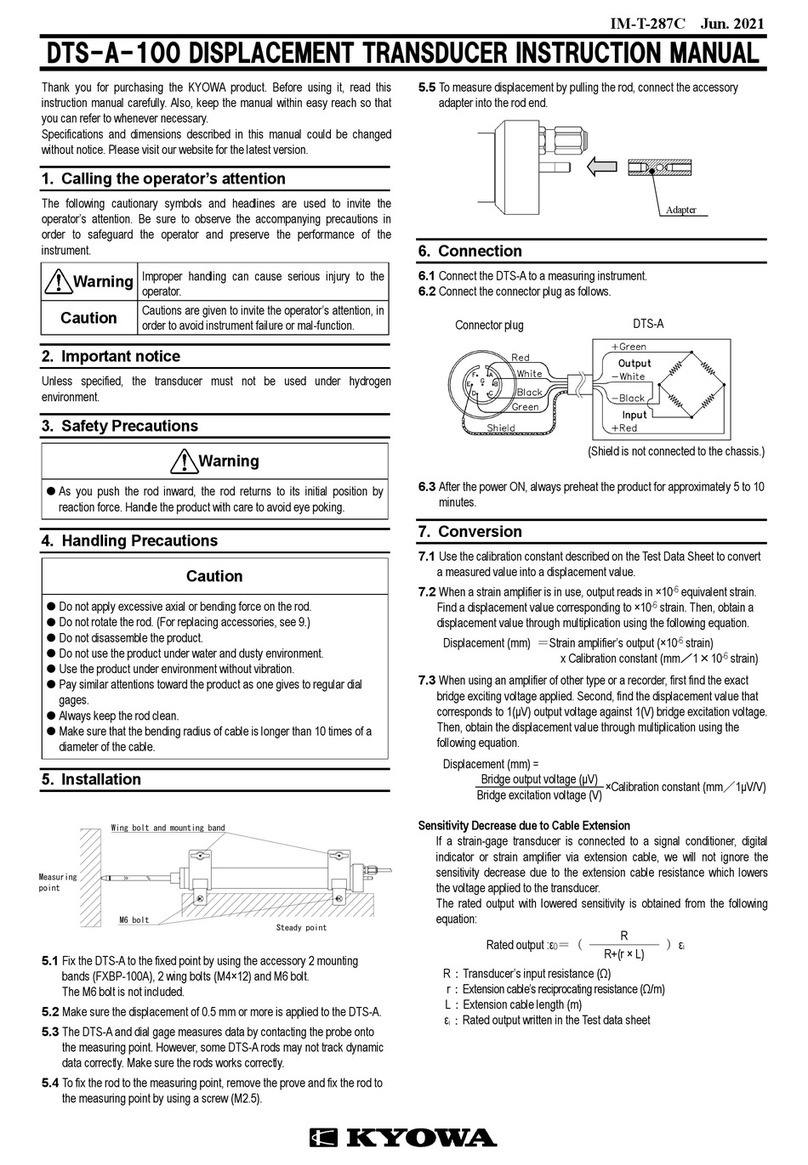
KYOWA DTS-A-100 User manual

KYOWA

KYOWA DTS-A-100 User manual

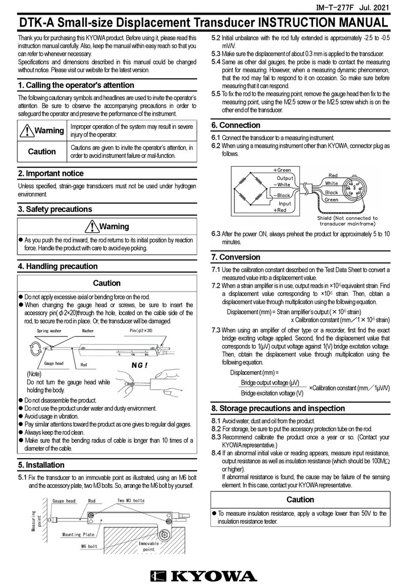
KYOWA DTK-A User manual

KYOWA

KYOWA DTK-A User manual

KYOWA PG-1TH User manual

KYOWA

KYOWA PG-1TH User manual

KYOWA DTT-A-100 User manual

KYOWA

KYOWA DTT-A-100 User manual

Popular Transducer manuals by other brands

Siemens SITRANS L 7ML1100 operating instructions

Siemens

Siemens SITRANS L 7ML1100 operating instructions

M-system L3CK instruction manual

M-system

M-system L3CK instruction manual

SIAP+MICROS t033 TDV User manual and maintenance

SIAP+MICROS

SIAP+MICROS t033 TDV User manual and maintenance

Mantracourt B24 user manual

Mantracourt

Mantracourt B24 user manual

Airmar P23 Owner's guide and installation instructions

Airmar

Airmar P23 Owner's guide and installation instructions

Simrad 50-7 -  REV B datasheet

Simrad

Simrad 50-7 - REV B datasheet

Balluff CANopen BTL5-H1-M-H/W Series manual

Balluff

Balluff CANopen BTL5-H1-M-H/W Series manual

TILLQUIST LQT40S user manual

TILLQUIST

TILLQUIST LQT40S user manual

Seneca T201DC100 Installation and user guide

Seneca

Seneca T201DC100 Installation and user guide

entegris NT 4150 user guide

entegris

entegris NT 4150 user guide

Lumel VTR06 user manual

Lumel

Lumel VTR06 user manual

Veris Hawkeye H421SP installation guide

Veris

Veris Hawkeye H421SP installation guide

Swagelok S user manual

Swagelok

Swagelok S user manual

Thyracont VSH88D operating instructions

Thyracont

Thyracont VSH88D operating instructions

MKS Baratron 722A manual

MKS

MKS Baratron 722A manual

Endress+Hauser Cerabar PMP23 operating instructions

Endress+Hauser

Endress+Hauser Cerabar PMP23 operating instructions

HBM T20WN Mounting instructions

HBM

HBM T20WN Mounting instructions

B-band A2 installation manual

B-band

B-band A2 installation manual

manuals.online logo
manuals.online logoBrands
  • About & Mission
  • Contact us
  • Privacy Policy
  • Terms and Conditions

Copyright 2025 Manuals.Online. All Rights Reserved.