Axis AXIS T95A00 User manual

ENGLISH DEUTSCH ITALIANO ESPAÑOL
INSTALLATION GUIDE
FRAN
Ç
AIS
AXIS T95A00 Dome Housing
AXIS T95A10 Dome Housing


AXIS T95A00/T95A10 Dome Housing Page 3
ENGLISH
AXIS T95A00/T95A10 Dome Housing
The AXIS T95A00/T95A10 Dome Housing can be used in both indoor and outdoor camera
installations. Follow these instructions to complete the installation of the AXIS T95A00/T95A10
Dome Housing and Axis network camera.
Warning! High voltage - the electrical connection must be made by an authorized electrician.
Please observe relevant national and local regulations for the installation.
•“Package Contents” on page 4
•“Installation” on page 5
•“Technical Specifications” on page 15
Safety Rules
Only qualified technical personnel must install this device.
• Disconnect the power supply before any technical work on the appliance.
• Do not use old or worn out power supply cables.
• Never make changes or connections that are not shown in this handbook; improper use of
the appliance may cause serious hazard and may damage the product.
• Use original spare parts. Non-original spare parts could cause fire, electrical discharge, or
other hazards.
• Before installing the device, check the supplied material to make sure it corresponds with
the order specification.
• Please retain this manual for future reference.
Axis Network Cameras
The AXIS T95A00/T95A10 Dome Housing supports the following camera models:
Camera Model: Note:
• AXIS 213 PTZ Before you begin, make sure that the AXIS
T95A00/T95A10 Dome Housing package contents, power
supply, and the required cables, tools, and documenta-
tion are available. See “Package Contents” on page 4.
• AXIS 214 PTZ
• AXIS 215 PTZ
• AXIS 231D+/232D+
• AXIS 233D

Page 4 AXIS T95A00/T95A10 Dome Housing
Package Contents
Large box:
(1) AXIS T95A00/T95A10 Dome Housing
Small box:
(2) Domes - transparent and smoked
(1) Fastening ring for dome
(1) Rubber gasket for dome
(4) M3x10mm screws for fastening ring
Plastic bag:
(1) Plate for cable glands
(1) Gasket
(3) M16 cable glands
(1) M12 cable gland
(3) Plastic nuts for M16 cable glands
(1) Plastic nut for M12 cable glands
(3) M3x10mm screws
(3) M3x8mm screws
(4) M4x10mm screws
(3) M3 nuts
(4) M4 nuts
(4) Lock washers
(1) 1/4-inch screw for fixed network camera
(1) 3mm Allen key
Plastic bag:
(1) Desiccant salt bag
Additional parts:
(1) Power connector for AXIS 213 PTZ, AXIS 214 PTZ, and AXIS 215 PTZ
(1) Ethernet connector with 90 degree angle for AXIS 231D+/232D+

AXIS T95A00/T95A10 Dome Housing Page 5
ENGLISH
Tools not included
*The RJ45 connector is attached after the cable has been pulled through the cable gland.
Other required parts
Note:
Not all screws provided are required for all camera installations.
Installation
Prepare the following steps indoors before you proceed to do the installation outdoors. This will
save time at the installation site.
Attach Universal Adaptor plate to camera
1. Remove the top cover of the housing (with four screws) from the housing using the 3mm allen
key.
2. For AXIS T95A00 Dome Housing only - remove the two connectors (with black and blue cables)
attached to the power supply on the Universal Adapter plate.
3. Loosen the three screws holding the Universal Adaptor plate. Slightly rotate and remove the
Universal Adaptor plate.
4. Attach the Universal Adaptor plate to the camera. For details see page 13.
Phillips screw driver
RJ45 crimp tool*
Adjustable wrench
Bracket see www.axis.com for available brackets and accessories
Power cable AWG20, 100-240 VAC cable (AXIS T95A00 Dome Housing)
AWG22, 24 VAC cable (AXIS T95A10 Dome Housing)
Network cable CAT 5 shielded twisted pair (STP) cable recommended
RJ45 connector
Soft cloth Recommended for protecting the dome while installing the housing
Top cover Black
cable
Blue
cable
Universal
Adaptor plate

Page 6 AXIS T95A00/T95A10 Dome Housing
Note:
Do not install the camera in the housing at this point. Transport it carefully to the place of
installation first.
Fix the dome to the housing
Place the fastening ring over the dome. Insert the four
10mm M3 screws, so you hold the ring, the dome, and
the gasket together. Fix the dome (transparent or
smoked) on the bottom of the housing.
AXIS 213 PTZ, AXIS 214 PTZ, and AXIS 215 PTZ power connection
1. Connect the (provided) power connector to the 12 VDC output as shown in the picture.
2. Connect the network camera’s power cable.
AXIS T95A00/T95A10 Dome Housing output 12V DC
Camera power connector Housing
black
red
GND
12 V
fastening ring
Housing
Rubber gasket
Dome
Fastening ring
Network camera power connector
12V DC

AXIS T95A00/T95A10 Dome Housing Page 7
ENGLISH
AXIS 231D+/232D+ and AXIS 233D power connection
1. Unplug the connector from the 12 VDC power supply opposite the bracket opening as shown in
the illustration below.
2. Remove the green connector from the cables.
3. Connect the cables to the camera power input as described below:
AXIS 231D+/232D+
• AXIS T95A00 Dome Housing (24V DC)
• AXIS T95A10 Dome Housing (24V AC)
Connect the brown cable to the 24V AC/DC pins on the
AXIS 231D+/232D+ connection module (see illustration).
Note:
The AXIS 231D+/232D+ connection module contains a
rectifier so the cables can be connected either way.
AXIS 233D
• AXIS T95A00 Dome Housing (24V DC)
Connect the brown cable to the GND/DC- and AC/DC+ pins on
the AXIS 233D connector (See illustration).
Be careful to connect (+) and (-) on the correct pins.
• AXIS T95A10 Dome Housing (24V AC)
Connect the brown cable to the AC and AC/DC+ pins on the
AXIS 233D connector (See illustration).
24V
~
+
~
-
12 VDC
power supply
Brown cable
AXIS 231D+/ 232D+
24V AC/DC
Connection module
AXIS 233D
Connector
AC
AC/DC+
GND/DC-
12V out
GND
Line out
GND
Line/Mic in

Page 8 AXIS T95A00/T95A10 Dome Housing
Prepare the cable gland plate
Fix the four cable glands to the cable gland plate and place the cable gland plugs on them. Insert
the four M3 screws through the gasket and plate.
The preparation for the network camera installation is now complete.
Install the bracket
Note:
Make sure all cables are in place and not powered, before you install the bracket. Keep
cables unpowered until the installation is complete.
1. Install the bracket for the AXIS T95A00/T95A10 Dome Housing on a wall and make sure that
the screws and plugs are appropriate for the wall (wood, metal, concrete, or any other), and
suitable for the weight of the housing. To install the bracket in the correct direction, see figure
below.
2. Pull a sufficient length of the cables through the bracket for the housing and camera
(approximately 50 cm).
Note:
Visit the Axis web site at www.axis.com for a comprehensive list of the available brackets
and accessories.
3170
182
150
81
230
14
140
110
77
9
14

AXIS T95A00/T95A10 Dome Housing Page 9
ENGLISH
Mount the housing to the bracket
Notes:
• Ensure that the bracket is securely fastened, and cables are pulled through it before mounting the
camera housing. Ensure that no power is connected to the cables.
• It is recommended that you place a soft, clean cloth (not included) into the dome to ensure it
remains clean until the time when you need to mount the camera.
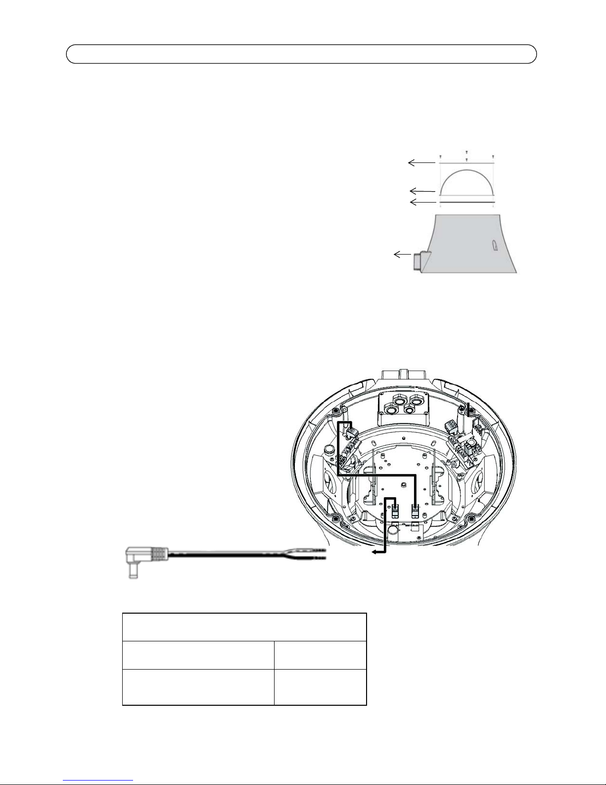
1. If the top cover of the housing was attached to facilitate transportation, detach it again at this
point.
2. Position the AXIS T95A00/T95A10 Dome Housing against the bracket, making sure to pull the
cable wires (power, Ethernet, and I/O cables if applicable) into the housing, and tighten the two
25mm M5 allen key screws (included with the bracket).
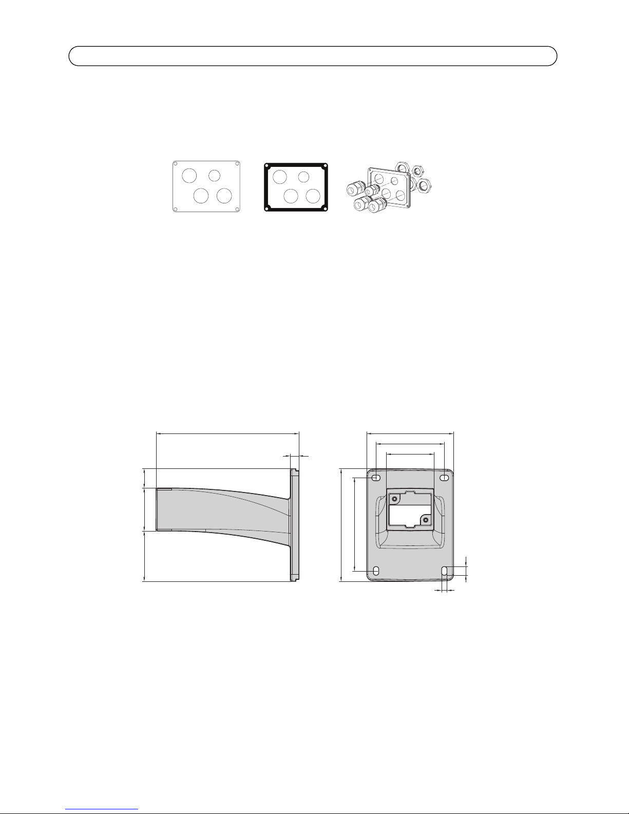
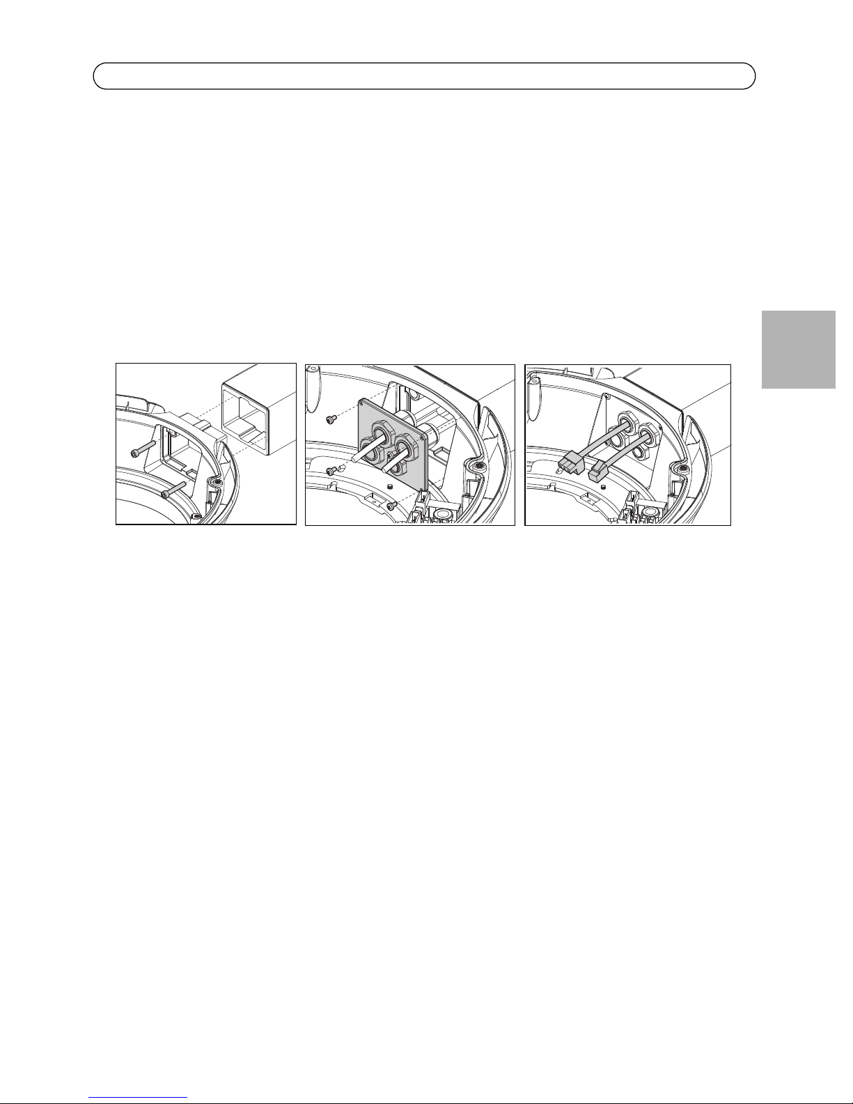
3. Pull the cable wires through the cable glands, and secure the hole in the bracket with the cable
gland plate. Ensure the cable wires are securely fastened in the cable glands.
4. Mount the RJ45 connector to the Ethernet cable, using an RJ45 crimp tool (not provided).
5. Remove the protective cloth (if you have used one) from the dome, and remove traces of dust.
Install the camera in the housing
1. Make sure power disconnected before the camera is installed.
1. Connect the network cable to the Ethernet port in the camera.
2. Connect the power cable to the camera.
3. If applicable, connect the I/O cables to the connectors as described in the installation guide
supplied with the camera.
4. Lower the Universal Adaptor plate with the attached camera into the AXIS T95A00/T95A10
Dome Housing and tighten the screws.
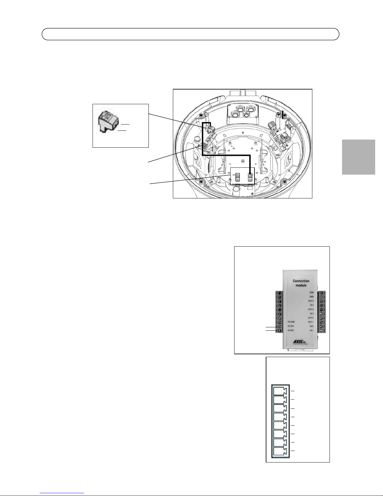
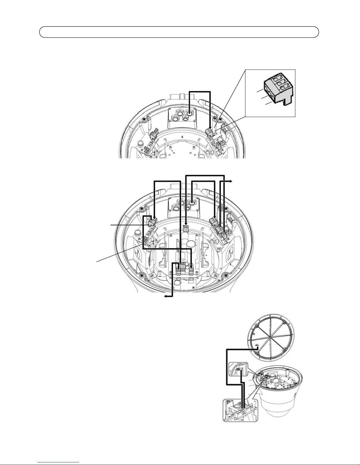
5. Connect the power cable to the housing as described below.
•“For AXIS T95A00 Dome Housing” on page 10
•“For AXIS T95A10 Dome Housing” on page 11

Page 10 AXIS T95A00/T95A10 Dome Housing
For AXIS T95A00 Dome Housing
Attach the power cable (100-240 volt AC) to the housing.
Earth the housing applying the two supplied cables
to the cover and body using M3 screws and the
toothed washer.
100-240V AC
100-240V AC input
Out 24V DC
Overview of complete installation
N
L
GND
Black Blue
In 100-240V AC Out 230V AC
Out 12V DC
Brown
cable

AXIS T95A00/T95A10 Dome Housing Page 11
ENGLISH
For AXIS T95A10 Dome Housing
Attach the power cable (24V AC) to the housing.
The safety wire should remain fastened during service.
Place the desiccant bag on the side of the housing
away from cables and electrical components.
Note:
For AXIS 231D+/232D+:
Place the connection module in a suitable position on
top of the bracket away from cables and electrical
components.
Overview of complete installation
Out 24V AC
N 24V AC
L 24V AC
GND
Out 12V DC
Brown
In 24V AC
Red
Desiccant bag

Page 12 AXIS T95A00/T95A10 Dome Housing
Complete the installation
Note:
Make sure that power remains disconnected while you complete the installation.
1. Check that all cables and wires in the housing are properly connected.
2. Follow the instructions in the Installation Guide to install the camera on the network.
3. Once the installation is complete, close the top cover of housing and tighten the screws to lock
the housing using the supplied Allen key.
4. Connect the AC mains power cable.
The installation is now complete.
The Axis network camera installation guide is shipped with the camera or available from the Axis
website at www.axis.com.
If you want to remove the sunshield
Remove the three screws on the side of the sunshield with a Phillips screw driver; remove the screw
on the top center of the cover plate with the 4 mm Allen key.
It is recommended that this is done after the installation.

AXIS T95A00/T95A10 Dome Housing Page 13
ENGLISH
Mount the Universal Adaptor plate to camera
The Universal Adaptor plate consists of five
plates.
Universal adaptor plate when assembled
Fixed plate
Spacer plate
AXIS 233D plate
Moving plate
Spacer plate
A
B
C
D
E
F
G
H
I
L
M
N
A
B
C
D
E
F
G
H
I
L
M
N
11
22
A
B
C
D
E
F
G
H
I
L
M
N
A
B
C
D
E
F
G
H
I
L
M
N
11
22
PF1
PF1
PF1
PF1
PF3
PF3
PF3
PF3
PF2
PF2
PF2
PM3
PM7-PM8
PM2-PM5
PM8 PM4
PM3
PM3
PM7
PM10
PM6
PM6
PM6
PM10
PM1-PM10
PM7
PM7
PM4
PM4
PM7
PM7
PM4
PM8
PM9-PM11 PM2-PM5
PM2-PM5
PM9-PM11
PM1-PM10
PM1-PM3
Fixed plate Spacer plate Spacer plate
AXIS 233D plate
Moving plate

Page 14 AXIS T95A00/T95A10 Dome Housing
For AXIS 233D
1. Adjust the height of the spacer plates to hole F1 on the spacer plate.
2. Place the camera within the four ears of the Universal Adaptor plate
and screw it onto place.
For AXIS 213 PTZ
1. Detach the AXIS 233D plate by removing the three nuts.
2. Adjust the height of the spacer plates to hole B2 on the spacer plate.
3. Place the AXIS 213 PTZ on the Moving plate.
4. Fasten the AXIS 213 PTZ to the two PM 11 holes with two screws.
For AXIS 214 PTZ
1. Detach the AXIS 233D plate by removing the three nuts.
2. Adjust the height of the spacer plates to hole E1 on the spacer plate.
3. Place the AXIS 214 PTZ on the Moving plate.
4. Fasten the AXIS 214 PTZ to the three PM5 holes with three screws.
For AXIS 215 PTZ
1. Detach the AXIS 233D plate by removing the three nuts.
2. Adjust the height of the spacer plates to hole E2 on the spacer plate.
3. Place the AXIS 215 PTZ on the Moving plate.
4. Fasten the AXIS 215 PTZ to the four PM 10 holes with four screws and nuts.
For AXIS 231D+/232D+
1. Detach the AXIS 233D plate by removing the three nuts.
2. Detach the Moving plate, and the Spacer plates.
3. Attach the provided 90° angle Ethernet connector to the network camera.
4. Place the AXIS 231D+/232D+ on the fixed plate.
5. Fasten the network camera, and the camera holder to the three PF2 holes on the fixed plate
with three screws.
6. Attach the network camera to the holder.

AXIS T95A00/T95A10 Dome Housing Page 15
ENGLISH
Technical Specifications
General
Built in die-cast aluminium
Epoxypolyester powder painting
RAL9002 color
RAL9002 color
Lower dome in polycarbonate Smoked or transparent
Sunshield in ABS for outdoor RAL9002 color
Mechanical
External dimensions with sunshield Ø 351x335mm (13.8x13.2in)
External dimensions without sunshield Ø 314x322mm (12.4x12.7in)
4 cable-glands 3xM16 with Ø cable 3,5-7mm (0.1-0.3in),1xM12
with Ø cable 5-10mm (0.2-0.4in)
Other User’s manual, cable glands and protective gasket
Electrical
Fan assisted heater, Ton 15°C +/-3°C (59°F +/-5°F)
Toff 22°C +/-3°C (71°F +/-5°F)
• AXIS T95A00 Dome Housing:
IN 230Vac, consumption 44W max
• AXIS T95A10 Dome Housing:
IN 24Vac, consumption 24W max
Camera power supply included with internal
adapter
• AXIS T95A00 Dome Housing
• IN 100/240Vac, 50/60Hz, OUT 12Vdc, 3A max
• IN 100/240Vac, 50-60Hz, OUT 24Vdc, 1.5A max
• AXIS T95A10 Dome Housing
• IN 24Vac, 50/60Hz, OUT 12VDC, 2A max
Blower in continuous duty for heater assistance Ton: 15°C +/-3°C (59°F +/-5°F) Toff 22°C +/-3°C (71°F
+/-5°F)
Related products
AXIS T95A61 Wall bracket
AXIS T95A64 Pole adapter
AXIS T95A67 Corner adapter
Environment

Page 16 AXIS T95A00/T95A10 Dome Housing
Indoor / Outdoor Operating temperature: -30°C / +50°C (-4°F /
+122°F)
Compliance to
• CE according to EN61000-6-3, EN 60950, EN50130-4
• IP66 according to EN 60529
Package
Unit weight AXIS T95A00 Dome Housing / AXIS T95A10 Dome
Housing - 3.8kg / 8.3lb
Package weight 4.2kg / 9.3lb
Package dimensions (BxHxL) 38.5x38.5x47cm / 15.1x15.1x18.5in
General

Boîtier du dôme AXIS T95A00/T95A10 Page 17
FRANÇAIS
FRAN
Ç
AIS
Boîtier du dôme AXIS T95A00/T95A10
Vous pouvez utiliser le Boîtier du dôme AXIS T95A00/T95A10 pour installer des caméras aussi bien à
l'intérieur qu'à l'extérieur. Suivez ces instructions pour mener à bien l'installation du Boîtier du
dôme AXIS T95A00/T95A10 et de la caméra réseau Axis.
Avertissement ! Haute tension : le raccordement électrique doit être effectué par un électricien
professionnel. Respectez les réglementations nationales et locales lors de l'installation.
•« Contenu de l'emballage » à la page 18
•« Installation » à la page 19
•« Caractéristiques techniques » à la page 29
Règles de sécurité
• L'installation de cet appareil doit être effectuée par un technicien qualifié.
• Coupez l'alimentation avant d'effectuer toute tâche d'ordre technique sur l'appareil.
• N'utilisez pas des câbles d'alimentation anciens ou usés.
• N'effectuez jamais de modifications ni de connexions non mentionnées dans ce manuel.
Une utilisation inadéquate de l'appareil peut constituer un danger pour le personnel et
nuire à l'installation.
• Utilisez des pièces détachées d'origine. Les pièces détachées qui ne sont pas d'origine peu-
vent causer des dommages tels qu'un incendie, une décharge électrique, etc.
• Avant d'installer le dispositif, vérifiez le matériel afin de vous assurer qu'il correspond à la
commande effectuée.
• Conservez ce manuel pour pouvoir vous y reporter ultérieurement.
Caméras réseau Axis
Le Boîtier du dôme AXIS T95A00/T95A10 prend en charge les modèles de caméra suivants :
Modèle de caméra : Attention :
• Caméra réseau AXIS 213 PTZ Avant de commencer, vérifiez que
l'emballage du Boîtier du dôme
AXIS T95A00/T95A10 contient le
câble d'alimentation et autres
câbles, ainsi que les outils et la
documentation nécessaires.
Reportez-vous à la « Contenu de
l'emballage » à la page 18.
• Caméra réseau AXIS 214
• Caméra réseau AXIS 215
• Caméra réseau AXIS 231D+
• Caméra réseau AXIS 232D+
• Caméra réseau AXIS 233D

Page 18 Boîtier du dôme AXIS T95A00/T95A10
Contenu de l'emballage
Contenu de la grande boîte
(1) Dôme Boîtier du dôme T95A
Contenu de la petite boîte
(2) Dômes : transparent et fumé
(1) Bague de fixation pour le dôme
(1) Joint en caoutchouc pour le dôme
(4) Vis M3 x 10 mm pour fixer la bague
Contenu du sac en plastique
(1) Plaque pour presse-étoupe
(1) Joint
(3) Presse-étoupe M16
(1) Presse-étoupe M12
(3) Écrou de serrage en plastique pour presse-étoupe M16
(1) Écrou de serrage en plastique pour presse-étoupe M12
(3) Vis M3 x 10 mm
(3) Vis M3 x 8 mm
(4) Vis M4 x 10 mm
(3) Écrous M3
(4) Écrous M4
(4) Rondelles de blocage
(1) Vis ¼ pouce pour fixer la caméra réseau
(1) Clé hexagonale 3 mm
Contenu du sac en plastique
(1) Sachet de sel anti-condensation
Pièces supplémentaires
(1) Connecteur d'alimentation pour Caméra réseau AXIS 213 PTZ, Caméra réseau
AXIS 214 et Caméra réseau AXIS 215
(1) Connecteur Ethernet avec angle 90 degrés pourla
Caméra réseau AXIS 231D+ et la
Caméra réseau AXIS 232D+

Boîtier du dôme AXIS T95A00/T95A10 Page 19
FRANÇAIS
FRAN
Ç
AIS
Outils non inclus
*Le connecteur RJ45 doit être fixé une fois que vous avez fait passer le câble dans le presse-étoupe.
Attention :
Les vis fournies ne sont pas nécessaires pour toutes les installations de caméra.
Autres éléments nécessaires
Installation
Vous pouvez effectuer les opérations suivantes à l'intérieur avant de procéder à l'installation à
l'extérieur. Vous gagnerez du temps au moment de l'installation.
Fixer une plaque d'adaptateur universel à la caméra
1. Retirez le couvercle supérieur (ainsi que les quatre vis) du boîtier AXIS T95A à l'aide la clé hex-
agonale de 3 mm.
2. Pour le Boîtier du dôme AXIS T95A00 uniquement, retirez les deux connecteurs (avec des câbles
bleu et noir) fixés à la source d'alimentation sur la plaque de l'adaptateur universel.
tournevis à pointe cruciforme
Outil de sertissage RJ45*
Clé ajustable
Support Pour obtenir la liste des supports et accessoires disponibles, consultez le site
www.axis.com.
Clip pour AWG20, câble 100-240 Vca (Boîtier du dôme AXIS T95A00)
AWG22, câble 24 Vca (Boîtier du dôme AXIS T95A10)
Câble de réseau Il est recommandé d'utiliser un câble à paires torsadées blindé (STP).
connecteur RJ45
Chiffon doux Recommandé pour protéger le dôme lors de l'installation du boîtier
Couvercle supérieur
Bleu
Noir
Plaque de
l'adaptateur
universel

Page 20 Boîtier du dôme AXIS T95A00/T95A10
3. Desserrez les trois vis en maintenant la plaque de l'adaptateur universel (environ 5 mm ou
0,75"). Faites légèrement pivoter la plaque de l'adaptateur universel et retirez-la.
4. Fixez la plaque de l'adaptateur universel à la caméra. Pour plus de détails, reportez-vous à la
page 27.
Attention :
N'installez pas encore la caméra dans le boîtier. Apportez-la avec précaution à l'endroit de
l'installation.
Fixez le dôme au boîtier.
1. Placez la bague de fixation sur le dôme.
Insérez les quatre vis M3 de 10 mm afin de
fixer la bague, le dôme et le joint ensemble.
Fixez le dôme (transparent ou fumé) en bas
du boîtier.
Préparer l'alimentation
Branchez le câble d'alimentation de la caméra
réseau.
Pour la Caméra réseau AXIS 213 PTZ, la Caméra réseau AXIS 214 et la Caméra réseau AXIS 215,
branchez le connecteur d'alimentation (fourni) sur la sortie 12 Vcc comme indiqué sur l'illustration.
Boîtier du dôme AXIS T95A00/T95A10, sortie 12 Vcc
Connecteur d'alimentation de la caméra Boîtier
noir
rouge
Mise à la terre (GND)
12 V
bague de fixation
Dôme
Joint en caoutchouc
Dôme
Bague de fixation
12 Vcc
Connecteur d'alimentation
de la caméra réseau
Other manuals for AXIS T95A00
2
This manual suits for next models
1
Table of contents
Languages:
Other Axis Camera Accessories manuals
Popular Camera Accessories manuals by other brands

Ikelite
Ikelite 6170.12 instructions

Aigis Mechtronics
Aigis Mechtronics HS9369 Series Installation and operating instructions

BAE
BAE OPzV Series Installation and operating instructions

Gradus Group
Gradus Group Vello Snap-On LCD Screen Protector user manual

Vitek
Vitek VT-PTHSG datasheet

Kodak
Kodak DS KSDMI4GBCSCAD Specifications