D
Q
R
1
2
G
H
Z
A
E
D
E
D
C
R
B
P
G
H
L
G
T
P
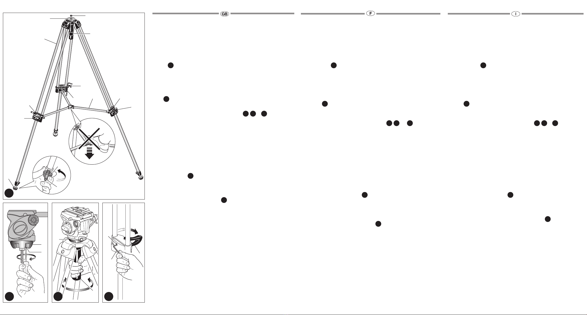
INTRODUCTION
Lightweight video tripod made of a technical polymer with aluminium anodised
legs and aluminium casting ball.
KEY FEATURES
• Mid level spreader
• 60 mm diameter ball
• Rubber feet with retractable spikes
SET UP
Unlock the each of the clips “B”
Spread the 3 legs “A” until the mid level spreader “C” is parallel on the floor.
To adjust the height of the tripod, each leg has telescopic extensions that can
be released by rotating lever “D” on the locking collar “E”. When the required
height is achieved, lock lever “D”.
FEET
The tripod has rubber feet “P” with retractable spikes “T” for external use.
MOUNTING AND REMOVING A CAMERA HEAD
Remove the cap “Z” (fig. 1).
Remove the half ball “G” (fig. 1), by unscrewing completely the handle “H”.
To mount your head simply screw the ball stud into the base of your head.
The half ball “G” (fig. 2) also has three screws “L” set in the ball.
After mounting head on the half ball “G”, tighten the three set screws “L” up
against the base of the head, with a small screwdriver, taking care not to force
them.
This unique feature, which works especially well with Manfrotto heads due to
their specially designed base, prevents the head unscrewing accidentally.
To remove the head, simply follow the above instructions in reverse.
Re mount the half ball “G” on the tripod (fig. 3), and lock it with handle “H”.
HEAD LEVELLING
To level the head, loosen the half ball “G” using the handle “H” move the ball
and head until a level has been achieved.
Once this has been done, lock the ball firmly using the handle “H”.
LEG LOCK TENSION ADJUSTMENT
If the telescopic leg extensions slip even with the locking lever “D” closed, the
locking tension will need to be adjusted.
In order to do this, release lock lever “D” then turn the screw “Q” clockwise
using the special key “R” provided on one of the tripod legs.
Normally a third of a turn will be sufficient to achieve the correct locking
tension.
INTRODUCTION
Trépied vidéo léger en polymère doté de jambes en aluminium anodisé et d’un
bol en fonderie d’aluminium.
CARACTÉRISTIQUES PRINCIPALES
• Entretoise du milieu
• Bol d’un diamètre de 60 mm
• Embouts en caoutchouc et pointes rétractables
INSTALLATION
Ouvrez les attaches “B”.
Écartez les 3 jambes “A” jusqu’à ce que l’entretoise du milieu “C” soit parallèle
au sol.
Pour régler la hauteur du trépied, déployez les sections télescopiques des
jambes en ouvrant les leviers de blocage "D" situés sur les bagues "E". Une fois
votre trépied à la hauteur souhaitée, bloquez les jambes à l’aide des leviers "D".
EMBOUTS
Les trépieds sont équipés d’embouts en caoutchouc "P" avec pointes
rétractables "T" spécialement conçus pour une utilisation en extérieur.
MONTAGE ET DEMONTAGE D’UNE ROTULE
Retirez le bouchon en caoutchouc “Z” (fig. 1).
Retirez la demi - boule “G” (fig. 1) en dévissant complètement la poignée “H”.
Pour monter votre rotule, vissez la simplement sur la base de la boule.
La demi - boule “G” (fig. 2) est également dotée de 3 vis “L”.
Après avoir fixé la rotule sur la demi - boule “G”, et avec un petit tournevis,
vissez les trois vis sans têtes “L” jusqu’à ce qu’elles soient en butée contre la
base de la rotule en faisant attention à ne pas les forcer.
Cette caractéristique est adaptée à toutes les rotules Manfrotto, leur base
ayant une forme spécifique, empêchant ainsi tout desserrage accidentel.
Pour retirer la rotule, suivez tout simplement les instructions ci dessus dans le
sens inverse.
Remontez la demi - boule “G” sur le trépied (fig. 3), et bloquez la avec la
poignée “H”
MISE A NIVEAU DE LA ROTULE
Pour mettre à niveau la rotule, desserrez la demie sphère “G” en utilisant
la poignée “H”, bougez la boule et la rotule jusqu’à l’obtention de la mise à
niveau.
Une fois obtenue, bloquez la boule fermement avec la poignée “H”.
REGLAGE DU BLOCAGE DES JAMBES
Si les sections télescopiques des jambes coulissent après que vous avez
bloqué le levier de blocage “D”, il faut régler le système de blocage des
jambes. Pour cela, débloquez d’abord le levier “D” et tournez la vis “Q” dans le
sens des aiguilles d’une montre à l’aide de la clé “R” fournie (attachée à l’une
des jambes). Un tiers de tour doit suffire pour rendre le système de blocage à
nouveau efficace.
INTRODUZIONE
Treppiede video leggero con parti realizzate in tecnopolimero, gambe in
alluminio anodizzato e semisfera in fusione di alluminio.
CARATTERISTICHE PRINCIPALI
• Stabilizzatore intermedio
• Culla con semisfera diametro 60 mm
• Piedini in gomma retraibili su puntali
PREPARAZIONE
Sbloccare i fermagli “B”.
Divaricare le 3 gambe “A” ed estendere lo stabilizzatore “C” fino a portarlo
parallelo al terreno.
Per regolare l’altezza del treppiede, ogni gamba dispone di allungamenti
telescopici che si possono liberare ruotando la leva “D” sul manicotto “E”.
Ottenuta l’altezza desiderata, bloccare la leva “D”.
PIEDINI
Il treppiede è dotato di piedini in gomma “P” con puntai retraibili “T” per
l’uso in esterni.
MONTAGGIO E SMONTAGGIO DELLE TESTE
Togliere la protezione “Z” (fig. 1)
Il treppiede ha un sistema esclusivo per evitare lo svitamento involontario
della testa, sistema che permette tuttavia di togliere e cambiare testa in
qualsiasi momento.
Togliere la semisfera “G” (fig. 1) svitando completamente la manopola “H
La semisfera “G” (fig. 2) dispone di tre grani “L” che normalmente non
sporgono dalla superficie. Dopo aver avvitato la testa sulla semisfera “G”
avvitare senza forzare, con un piccolo cacciavite, i tre grani “L” contro
la base della testa. Ciò per il disegno particolare della base della testa,
impedirà che la stessa possa svitarsi accidentalmente.
Per toglierla è necessario allentare i tre grani “L”.
Montare la semisfera “G” nel treppiede (fig. 3) bloccandola mediante la
manopola “H”
LIVELLAMENTO DELLA TESTA
Per livellare la testa è sufficiente agire sulla manopola “H” (fig. 3) per
allentare il bloccaggio della semisfera “G” nella sua sede: trovata la
posizione di livellamento serrare completamente la manopola “H.
REGOLAZIONE DEL BLOCCAGGIO DELLE GAMBE
Se le sezioni telescopiche delle gambe tendono a scivolare anche con le
leve di blocco “D” chiuse, occorre regolare la tensione di bloccaggio.
A questo scopo, aprire la leva di blocco “D” e ruotare in senso orario la vite
“Q” usando la chiave speciale “R” inserita su una delle gambe del treppiede.
Normalmente basta un terzo di giro per ottenere la corretta tensione di
bloccaggio.
1
432


