marklin 59080 User manual

59080
Digital-Decoder
Digital Decoder
Décodeur numérique à installer
Inbouw-digitaaldecoder
Decoder digital integrable
Decoder Digital installabile

2
Inhaltsverzeichnis Seite
Bestimmungsgemäße Verwendung 4
Lieferumfang 4
Sicherheitshinweise 4
Wichtige Hinweise 4
Funktionen 4
Decoder-Einbau 5
Entsorgung 5
Garantie 5
CV Programmierung 6
Programmier-Tabellen 24
Table of Contents Page
Normal Use 7
Contents as Delivered 7
Safety Notes 7
Important Information 7
Functions 7
Decoder Installation 8
Disposal 8
Warranty 8
CV Programming 9
Programming Table 24
Sommaire Page
Usage conforme 10
Matériel fourni 10
Consignes de sécurité 10
Indications importantes 10
Fonctions 10
Installation du décodeur 11
Elimination 11
Garantie 11
Programmation des CV 12
Tableau de programmation 24
Inhoudsopgave Pagina
Beoogd gebruik 13
Leveringsomvang 13
Veiligheidsvoorschriften 13
Belangrijke aanwijzingen 13
Werking 13
Decoder inbouwen 14
Afdanken 14
Garantie 14
CV-programmering 15
Programmeertabel 24

3
Índice Página
Uso previsto 16
Alcance de suministro 16
Instrucciones de seguridad 16
Notas importantes 16
Funciones 16
Montaje del decoder 17
Eliminación 17
Garantía 17
Programación de variables CV 18
Tabla de programación 24
Elenco del contenuto Pagina
Impiego commisurato alla destinazione 19
Corredo di fornitura 19
Avvertenze di sicurezza 19
Avvertenze importanti 19
Funzioni 19
Montaggio del Decoder 20
Smaltimento 20
Garanzia 20
Programmazione delle CV 21
Tabella di programmazione 24

4
Bestimmungsgemäße Verwendung
• Der Einbau-Digital-Decoder ist zum Einbau in Märklin
Spur 1-Weichen mit Weichenantrieb 59079 bestimmt.
• Darf nur in trockenen Räumen verwendet werden.
Lieferumfang
Decoder
2 Schrauben
Einbauanleitung
Garantieurkunde
Für den Einbau zusätzlich benötigtes Werkzeug: Pinzette und Löt-
station für eine Löttemperatur bis max. 30W/300˚mit dünner Spitze,
Elektronik-Lötzinn (Ø 0,5-1 mm), Entlötlitze oder Entlötsaugpumpe.
Sicherheitshinweise
• ACHTUNG! Funktionsbedingte scharfe Kanten und Spitzen.
• Verkabelungs- und Montagearbeiten nur im spannungslosen
Zustand ausführen. Bei Nichtbeachtung kann es zu gefähr-
lichen Körperströmen und damit zu Verletzungen führen.
•Decoder nur mit der zulässigen Spannung (siehe technische
Daten) betreiben.
Beim Umgang mit dem Lötkolben besteht die Gefahr von
Hautverbrennungen.
Wichtige Hinweise
• Achtung: Beim Einbau möglichst keine Bauteile auf der
Oberseite des Einbau-Digital-Decoders berühren, statische
Aufladung kann die Funktion beeinträchtigen.
• Die Bedienungsanleitung ist Bestandteil des Produktes und
muss deshalb aufbewahrt sowie bei Weitergabe des Produk-
tes mitgegeben werden.
• Für Reparaturen wenden Sie sich bitte an Ihren Märklin-
Fachhändler.
• http://www.maerklin.com/en/imprint.html
Technische Daten
• Belastung Weichenausgang max. 300 mA
• Spannung Digitalstromkreis max. 20 V eff.
• Spannungsfestigkeit max. 40 V
Funktionen
• Multiprotokoll fähig: fx (MM) und DCC
• Einstellen der Betriebsart mittels DIP-Schalter
• Einstellbare Adressen mit DIP-Schalter:
1-256 fx (MM) (Control Unit 6021/Mobile Station 60651/652)
1-320 fx (MM) (Central Station 6021x/Mobile Station 60653)
1-511 (DCC)
• Programmierbare Adressen über CV –>
1-2044 DCC
• Änderungen der Eigenschaften über CV
• Stromversorgung über Digitalstromkreis

5
Decoder-Einbau
Änderungen der Eigenschaften im fx (MM)-Protokoll durch CV
Programmierung oder zur DCC CV-Programmierung folgen Sie
dem Kapitel „CV Programmierung.“
Folgende Arbeitsschritte dürfen nur im spannungslosen Zustand
ausgeführt werden:
Beachten Sie, dass Einstellungen mit dem DIP-Schalter immer
spannungslos vorzunehmen sind. Der Einbau-Digital-Decoder
erkennt erst mit dem Einschalten der Spannung die aktuellen
Schalterstellungen.
Ab Seite 24 finden Sie die Tabelle für die Adressierung mit DIP-
Schalter.
Einbau des Einbau-Digital-Decoders in Märklin-Weiche siehe
Seite 22.
Entsorgung
Hinweise zum Umweltschutz: Produkte, die mit
dem durchgestrichenen Mülleimer gekennzeichnet
sind, dürfen am Ende ihrer Lebensdauer nicht über
den normalen Haushaltsmüll entsorgt werden,
sondern müssen an einem Sammelpunkt für das
Recycling von elektrischen und elektronischen
Geräten abgegeben werden. Das Symbol auf dem
Produkt, der Bedienungsanleitung oder der Verpackung weist
darauf hin. Die Werkstoffe sind gemäß ihrer Kennzeichnung
wiederverwertbar. Mit der Wiederverwendung, der stofflichen
Verwertung oder anderen Formen der Verwertung von Altge-
räten leisten Sie einen wichtigen Beitrag zum Schutze unserer
Umwelt. Bitte erfragen Sie bei Ihrer Gemeindeverwaltung die
zuständige Entsorgungsstelle.
Garantie
Gewährleistung und Garantie gemäß der beiliegenden Garantie-
urkunde.
• Für Reparaturen wenden Sie sich bitte an Ihren Märklin-
Fachhändler oder an
Gebr. Märklin & Cie. GmbH
Reparaturservice
Stuttgarter Str. 55 - 57
73033 Göppingen
Germany
Tel: 07161 608 222

6
CV Programmierung
Die CV Programmierung muss am Programmiergleis erfolgen.
Für die Programmierung empfehlen wir, eine fiktive Lokomotive
anzulegen. Werte in Klammern sind die Werkseinstellungen.
Während der Datenübertragung blinkt zur Kontrolle die am
Einbau-Digital-Decoder angeschlossene Weichenlaterne.
fx (MM)
Vor der Programmierung muss die zu programmierende Weiche
mit dem Keyboard geschaltet werden. Danach unverzüglich mit
der Control Unit bzw. CV Konfiguration der Central Station die
CV geändert werden. Danach sofort die programmierte Weiche
wieder mit dem Keyboard schalten. Erst jetzt ist die Programmie-
rung übernommen und wirksam.
CV Bedeutung Werte
8Decoder-Reset 8 (-) Werkseinstellung, Wert
wird nicht geschrieben
37 Stellweg umkehren 0-1 (0) Ändert die Schaltrichtung
Die Vorgehensweise beim Programmieren mit der Control Unit
6021 entspricht der Lokprogrammierung (www.maerklin.de ->
Tools & Downloads -> Technische Informationen).
DCC
CV Bedeutung Werte
1 Adresse, niederwertige
Byte 0-255 (1)
7 Hersteller Versionsnum-
mer (Softwareversion) (-) nur lesen
8 Hersteller Kennung ID
Decoder Reset
(131)
8 (-)
nur lesen,
Werkseinstellung, Wert
wird nicht geschrieben
9 Adresse, höherwertige
Byte 0-7 (0)
29 Konfiguration (192) nur lesen
Bit 0-4 werden nicht
verwendet 0
Bit 5: Decodertyp 0 / 32 Basis- o. erweiterter
Zubehördecoder
Bit 6: Adressierungs-
methode 0 / 64 Decoder- o. Aus-
gangsadresse
Bit 7: Decoderart 128 Zubehördecoder
37 Stellweg umkehren 0-1 (0) Ändert die Schaltrich-
tung
Einstellen und errechnen der Adressen größer 255:
Z.B. Adresse 1044 -> 1044:256=4,078125 . Der Wert vor dem
Komma (4) ist in CV 9 einzutragen. Den Wert nach dem Komma
(0,078125) wird mit 256 multipliziert 0,078125x256=20. Der errech-
nete Wert 20 muss in CV 1 eingetragen werden.

7
Normal Use
• This digital installation decoder is designed for installation in
Märklin 1 Track turnouts with a turnout mechanism 59079.
• This decoder may only be used in dry areas indoors.
Contents as Delivered
1 digital installation decoder
2 screw
Installation instructions
Warranty card
Additional tools required for installation: tweezers and solder-
ing station for a maximum soldering temperature of 30 watts /
300˚ Celsius / 572˚ Fahrenheit with a fine point, Electronic solder
(0.5-1 mm dia.), desoldering braid or desoldering pump.
Safety Notes
• IMPORTANT! This product has sharp edges and points related
to its function.
• Do wiring and assembly work only in a voltage-free work
environment. Otherwise you may experience electrical current
dangerous to the body leading to injury.
•Operate this decoder only with the permissible voltage
(see technical information).
When using a solder station there is the danger of burning
your skin.
Important Information
• Important: When installing the digital installation decoder,
try to avoid touching components on the upper side of the
decoder. Static charge can affect the function of the decoder.
• The operating instructions are a component part of the
product and must therefore be kept with the product,
particularly when it is given to another party.
• For repairs please see your authorized Märklin specialty
dealer.
• http://www.maerklin.com/en/imprint.html
Technical Data
• Load at turnout output max. 300 amps
• Voltage for the digital power circuit max. 20 volts eff.
• Electrical strength max. 40 volts
Functions
• Capable of multi-protocols: fx (MM) and DCC
• Mode of operation set with DIP switches
• Addresses can be set with DIP switches:
1-256 fx (MM) (Control Unit 6021/Mobile Station 60651/652)
1-320 fx (MM) (Central Station 6021x/Mobile Station 60653)
1-511 (DCC)
• Programmable addresses using CVs –>
1-2044 DCC
• Changes to characteristics can be done with CVs
• Power supply done using the digital power circuit

8
Decoder Installation
See the section “CV Programming” for changes to other charac-
teristics in the fx (MM) protocol using CV programming or to the
DCC CV programming.
The following work steps may only be done in a voltage-free
work environment:
Note: Settings with the DIP switches are to be only when the
voltage is turned off. The digital installation decoder does not
recognize the current switch settings until the voltage is turned
on.
Starting on page 24 you’ll find the table for setting addresses
with DIP switches.
See page 22 for installation of the digital installation decoder
in Märklin standard turnouts, curved turnouts, or double slip
switches.
Disposal
Information about protecting the environment:
Products marked with a trashcan with a line
through it may not be disposed of at the end of
their useful life along with the normal household
trash. They must be taken to a collection point for
recycling electrical and electronic devices. The
symbol on the product, the instructions, or the pa-
ckaging indicates this. Depending on their description, the raw
materials can be used again. You make an important contribution
to the protection of our environment with the recycling of this
material from old devices. Please inquire in your community
about the appropriate disposal site.
Warranty
The warranty terms are stated on the warranty card included
with this product.
• Please see your authorized Märklin specialty dealer or
Gebr. Märklin & Cie. GmbH
Reparaturservice
Stuttgarter Str. 55 - 57
73033 Göppingen
Germany
Tel: +49 7161 608 222

9
CV Programming
CV programming must be done on the programming track.
We recommend creating a fictitious locomotive for programming
purposes. Values in parentheses are the factory settings.
The turnout lantern connected to the digital installation decoder
will blink as a control check during the data transmission.
fx (MM)
Before doing any programming, the turnout to be programmed
must be switched with the Keyboard. After that the CVs are
changed immediately with the Control Unit or the CV configura-
tion on the Central Station. After that the programmed turnout
is to be switched again with the Keyboard. At this point the
programming is accepted and is functional.
CV Meaning Values
8 Decoder reset 8 (-) factory setting, not written
value is
37 Reverse travel
range 0-1 (0) Changes the electrical
switching direction
The procedure for programming with the 6021 Control Unit is the
same as locomotive programming (www.maerklin.de -> Tools &
Downloads -> Technische Informationen).
DCC
CV Meaning Values
1Address, lower value
Byte 0-255 (1)
7Manufacturer version
number (software
version)
(-) read only
8Manufacture recognition
ID Decoder reset (131)
8 (-)
read only,
factory setting, value
is not written
9Address, higher value
Byte 0-7 (0)
29 Configuration (192) read only
Bits 0-4 are not used 0
Bit 5: Decoder type 0 / 32 basic or advanced
accessory decoder
Bit 6: Addressing method 0 / 64 decoder or output
address
Bit 7: Decoder type 128 accessory decoder
37 Reverse travel range 0-1 (0)
Changes the electrical
switching direction
Setting and generating addresses larger than 255:
Example: Address 1044 -> 1044:256=4,078125 . The value before
the comma (4) is to be entered in CV 9. The value after the com-
ma (0,078125) is multiplied by 256, 078125x256=20. The value of 20
that is generated must be entered in CV 1.

10
Usage conforme
• Le décodeur numérique est conçu pour être installé dans des
aiguilles de voie 1 Märklin équipées d‘un moteur 59079.
• A utiliser exclusivement dans des pièces sèches.
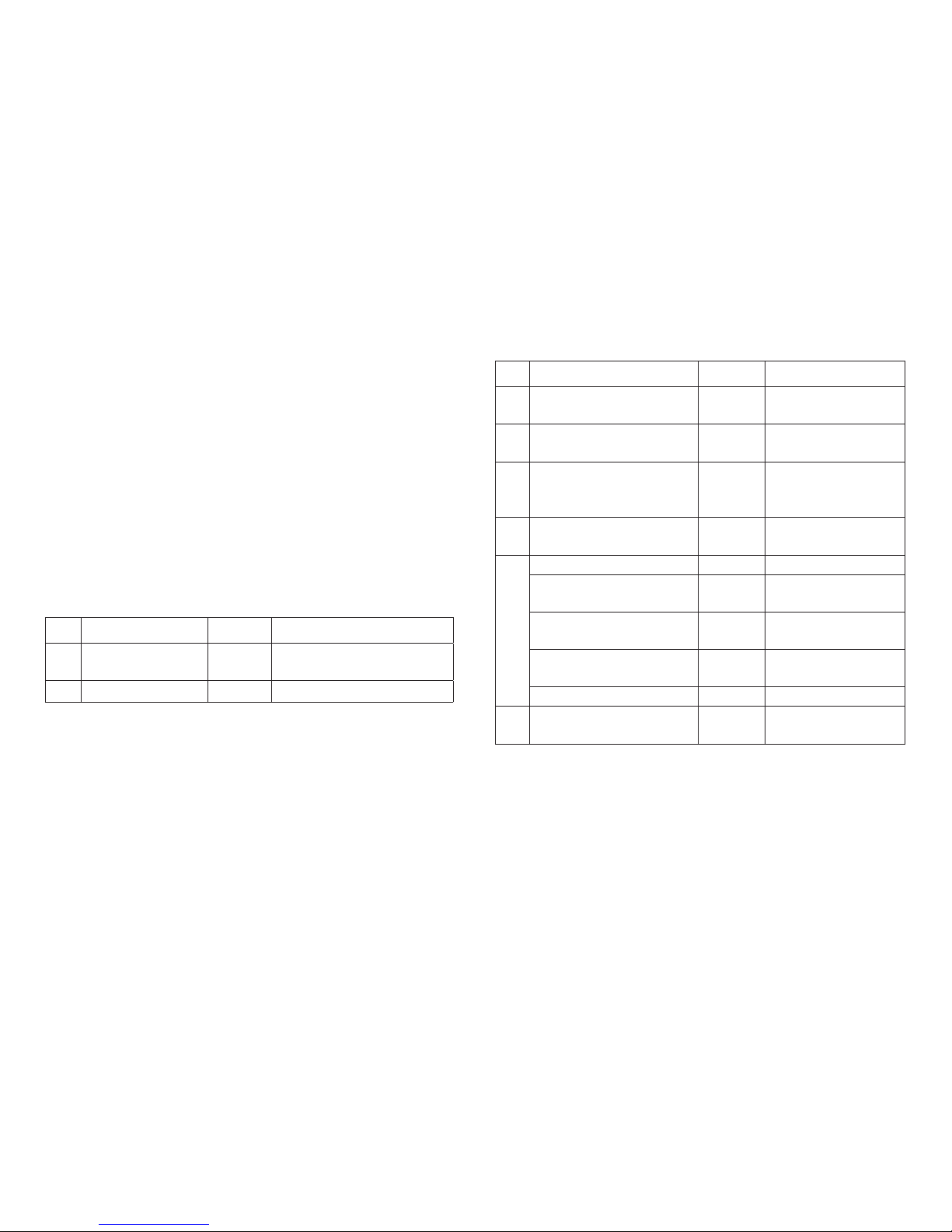
Matériel fourni
1 Décodeur numérique à installer
2
vis
Notice d’installation
Bon de garantie
Outils nécessaires à l’installation : Pincette et poste à ouder
pour une température de brasage maximale de 30 W/300˚avec
pointe fine, fil à souder pour électronique (Ø 0,5-1 mm), tresse à
dessouder ou pompe à dessouder.
Consignes de sécurité
• ATTENTION ! L’appareil présente des arêtes coupantes.
• Câblage et montage doivent être réalisés uniquement quand
l’appareil est hors tension. Le non respect de ces consignes
peut générer des courants de choc dangereux et être à
l’origine de blessures.
•Exploiter le décodeur uniquement avec la tension autorisée
(voir caractéristiques techniques).
Risques de brûlures lors de la manipulation du fer à
souder.
Indications importantes
• Attention : Lors de l’installation, éviter dans la mesure du
possible de toucher les composants situés sur la face supé-
rieure du décodeur numérique, une charge statique pouvant
entraver le fonctionnement.
• La notice d‘utilisation fait partie intégrante du produit ; elle
doit donc être conservée et, le cas échéant, transmise avec
le produit.
• Pour toute réparation, adressez-vous SVP à votre détaillant
spécialisé Märklin.
• http://www.maerklin.com/en/imprint.html
Caractéristiques techniques
• Charge sortie aiguille max. 300 mA
• Tension circuit numérique max. 20 V eff.
• Tenue en tension max. 40 V
Fonctions
• multi protocole: fx (MM) et DCC
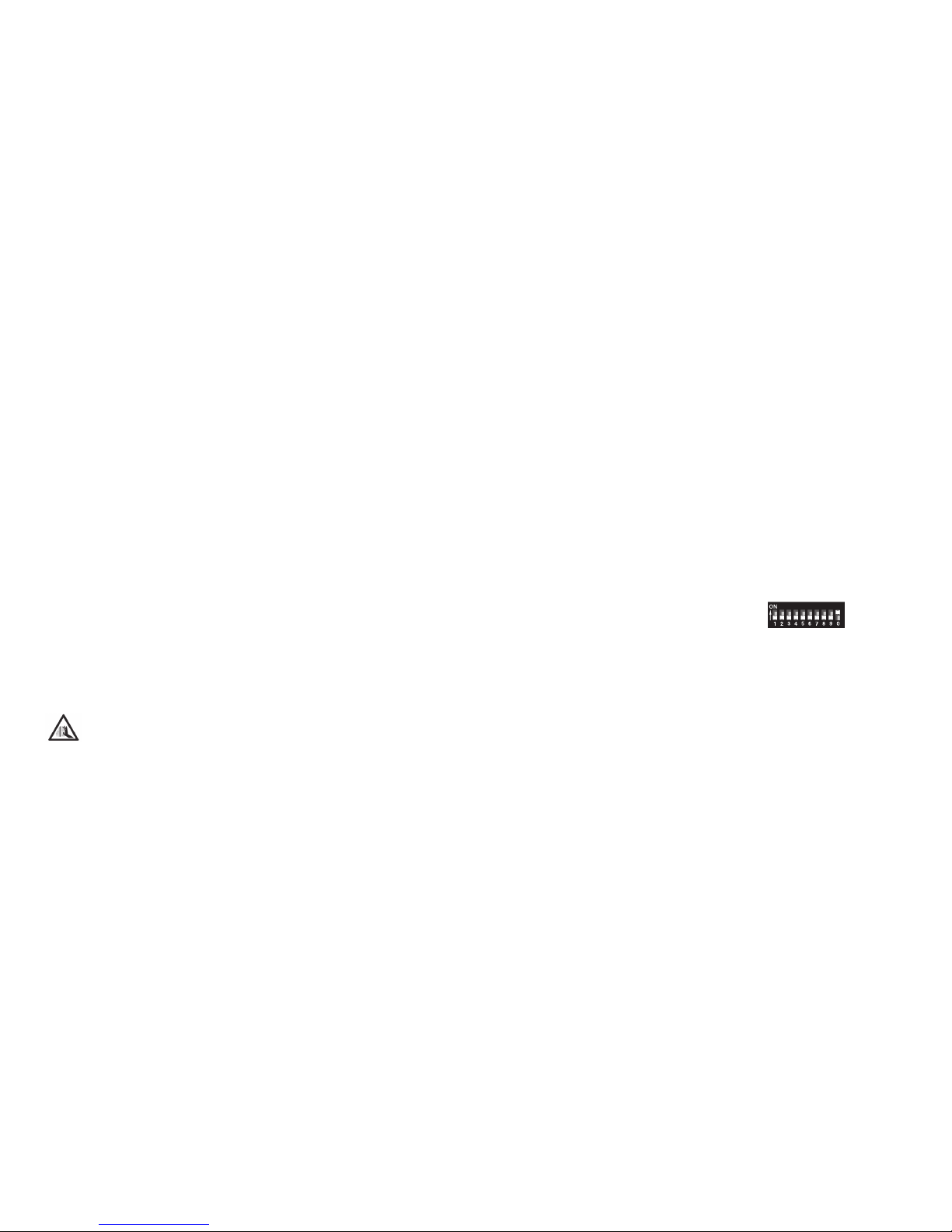
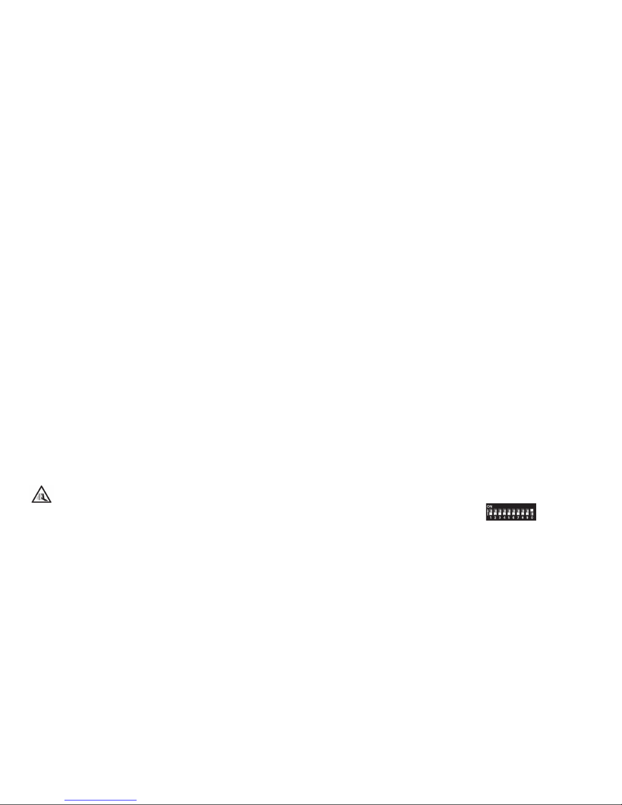
• Dé nition du mode d’exploitation via commutateur DIP
• Dé nition des adresses possible via commutateur DIP :
1-256 fx (MM) (Control Unit 6021/Mobile Station 60651/652)
1-320 fx (MM) (Central Station 6021x/Mobile Station 60653)
1-511 (DCC)
• Adresses programmables via CV –>
1-2044 DCC
• Modi cations des propriétés via CV
• Alimentation en courant via circuit numérique

11
Installation du décodeur
Pour modifier les autres caractéristiques dans le protocole
fx (MM) via la programmation des CV ou pour la programmation
des CV dans le protocole DCC, veuillez suivre les indications du
chapitre « Programmation des CV ».
L’installation, dont les différentes étapes sont décrites
ci-dessous, doit impérativement être réalisée hors tension :
Attention : Les paramétrages avec le commutateur DIP doivent
toujours se faire hors tension. Le décodeur numérique ne
reconnaît les nouvelles positions du commutateur qu’à la mise
sous tension.
Vous trouverez le tableau pour la définition des adresses avec
commutateur DIP à partir de la page 24.
Installation du décodeur numérique dans les aiguillages
Märklin : voir page 22.
Elimination
Indications relatives à la protection de
l’environnement : Les produits marqués du signe
représentant une poubelle barrée ne peuvent être
éliminés en n de vie via les ordures ménagères
normales, mais doivent être remis à un centre
de collecte pour le recyclage des appareils
électriques et électroniques. Le symbole figurant sur le produit
lui-même, la notice d’utilisation ou l’emballage l’indique. Les
matériaux sont recyclables selon leur marquage. Avec le
recyclage, la récupération des matériaux ou autres formes de
valorisation de vieux appareils, vous contribuez sensiblement
à la protection de notre environnement. Renseignez-vous
auprès de votre municipalité sur les centres compétents pour
le traitement des déchets.
Garantie
Garantie légale et garantie contractuelle conformément au bon
de garantie ci-joint.
• Pour toute réparation, veuillez vous adresser à votre
détaillant spécialisé Märklin ou à
Gebr. Märklin & Cie. GmbH
Reparaturservice
Stuttgarter Str. 55-57
73033 Göppingen
Germany
Tél. : +49 7161 608 222

12
Programmation des CV
La programmation des CV se fait sur la voie de programmation.
Pour la programmation, nous vous conseillons de créer une
locomotive ctive. Les valeurs indiquées entre parenthèses
correspondent aux paramètres d‘usine.
Durant la transmission des données, la lanterne d’aiguille
raccordée au décodeur numérique clignote (contrôle).
fx (MM)
Avant de procéder à la programmation, commutez l’aiguille à
programmer via le Keyboard. Modifiez ensuite sans attendre la
CV avec la Control Unit, respectivement via la fonction de confi-
guration des CV de la Central Station. Commutez alors à nouveau
et immédiatement l’aiguille programmée via le Keyboard. La
programmation est enfin enregistrée et effective.
CV Signification Valeurs
8Réinitialisation du
décodeur 8 (-) Paramètre d’usine, la va-
leur n’est pas enregistrée
37 Inverser la course
de manoeuvre 0-1 (0) Modifie le sens de com-
mutation
La procédure à suivre pour la programmation avec la
Central Unit 6021 correspond à la programmation de la loco
(www.maerklin.de -> Tools & Downloads -> Technische
Informationen).
DCC
CV Signification Valeurs
1 Adresse, octet de valeur
basse 0-255 (1)
7 Numéro de version fabri-
cant (version logicielle) (-) Lire uniquement
8 Identifiant du fabricant
Réinitialisation du
décodeur
(131)
8 (-)
Lire uniquement,
paramètre d’usine,
la valeur n’est pas
enregistrée
9 Adresse, octet de valeur
supérieure 0-7 (0)
29 Configuration (192) Lire uniquement
Bits 0 à 4 non utilisés 0
Bit 5: Type de décodeur 0 / 32 Décodeur
d‘accessoires de
base ou avancé
Bit 6: Méthode
d’adressage 0 / 64 Adresse du décodeur
ou adresse de départ
Bit 7: Type de décodeur 128 Décodeur
d’accessoires
37 Inverser la course de
manoeuvre 0-1 (0) Modifie le sens de
commutation
Définition et calcul des adresses supérieures à 255 :
Par ex. Adresse 1044 -> 1044:256=4,078125 . La valeur avant la
virgule (4) est à reporter dans la CV 9. La valeur située après
la virgule (0,078125) est multipliée par 256 0,078125x256=20.
La valeur calculée 20 est à reporter dans la CV 1.

13
Beoogd gebruik
• De inbouw-digitaaldecoder is bedoeld voor het inbouwen in
Märklin- 1-rail wissels met wisselaandrijving 59079.
• Mag alleen in droge ruimtes gebruikt worden.
Leveringsomvang
1 inbouw-digitaaldecoder
2 schroef
Gebruiksaanwijzing
Garantiebewijs
Voor het inbouwen is het volgende gereedschap nodig: pincet en
soldeerstation met een maximale temperatuur van 30 W/300° C
met een dunne stift, elektronica soldeertin (0.5 - 1mm), desoldeer-
litze of soldeertinzuiger.
Veiligheidsvoorschriften
• Let op! bevat vanwege zijn functie scherpe randen en punten.
• Bedrading- en montage alleen in spanningloze toestand uitvoe-
ren. Bij het niet naleven kunnen er gevaarlijke stromen door het
lichaam vloeien en verwondingen ontstaan.
• Decoder alleen met de toegelaten spanning (zie technische
gegevens) gebruiken.
Bij het werken met een soldeerbout bestaat het gevaar voor
brandwonden.
Belangrijke aanwijzingen
• Let op: bij het inbouwen de delen op de bovenzijde van de
inbouw-digitaaldecoder niet aanraken, statische ontlading
kan de juiste werking be invloeden.
• De gebruiksaanwijzing is onderdeel van het product en moet
derhalve bij de overdracht van het product meegegeven
worden.
• Voor reparaties kunt u zich tot uw Märklin dealer wenden.
• http://www.maerklin.com/en/imprint.hmtl
Technische gegevens
• Belasting wisseluitgang max. 300 mA
• Spanning digitale stroomkring max. 20 V eff.
• Diëlektrische sterkte max. 40 V
Werking
• Multiprotocol: fx (MM) en DCC
• Instellen van het bedrijfssysteem met DIP-schakelaar
• Instellen van het adres met DIP-schakelaar
1-256 fx (MM) (Control Unit 6021/Mobile Station 60651/652)
1-320 fx (MM) (Central Station 6021x/Mobile Station 60653)
1-511 (DCC)
• Programeerbare adressen via CV –>
1-2044 DCC
• Wijzigen van de eigenschappen via CV
• Stroomvoorziening via digitale stroomkring

14
Decoder inbouwen
Veranderen van de te wijzigende eigenschappen in het fx (MM)
protocol door CV programmering of het DCC CV programmering
vindt u in het hoofdstuk “CV programmering”.
De volgende stappen mogen alleen in spanningloze toestand
uitgevoerd worden:
Let op: instellingen van de DIP-schakelaars alleen in span-
ningloze toestand uitvoeren. De inbouw-digitaaldecoder herkend
de actuele schakelaarstand pas na het inschakelen van de
voedingsspanning.
Vanaf pagina 24 vindt u de tabel voor de adressering met de
DIP-schakelaars.
Inbouw van de inbouw-digitaaldecoder in de Märklin standaard-
meegebogen- en kruiswissels zie pagina 22.
Afdanken
Milieu-informatie: producten, die met de doorge-
streepte afvalcontainer zijn gemarkeerd, mogen
aan het einde van hun levensduur niet met het
normale huisvuil meegegeven worden, maar
moeten op een verzamelpunt voor de recycling van
elektrische en elektronische apparatuur afgegeven
worden. Het symbool op het product, op de handleiding of op de
verpakking geeft dit aan. De materialen worden gerecycled in
overeenstemming met hun identificatie. Met het hergebruik van
de grondstoffen of andere vormen van het hergebruik van oude
apparatuur levert u een belangrijke bijdrage aan de bescherming
van ons milieu. Neem contact op met uw gemeente voor een
bevoegde plaatselijke inzamelplaats.
Garantie
Waarborg en garantie volgens bijgevoegd garantiebewijs.
• Voor reparaties kunt u zich wenden tot uw Märklin dealer
of tot
Gebr. Märklin & Cie. GmbH
Reparaturservice
Stuttgarter Str. 55 - 57
73033 Göppingen
Germany
Tel: +49 7161 608 222

15
CV Programmering
De CV programmering moet via het programmeerspoor gebeu-
ren. Voor het programmeren is het aan te bevelen een fictive
loc aan te maken. De waarden tussen haakjes zijn de af fabriek
ingestelde waarden.
Tijdens de dataoverdracht knippert, ter controle, de aan de
inbouw-digitaaldecoder aangesloten wisselantaarn.
fx (MM)
Voor het programmeren moet de te programmeren wissel met
het keyboard geschakeld worden. Daarna onmiddellijk met de
Control Unit resp. via CV configuratie met het Central Station de
CV wijzigen. Daarna direct de geprogrammeerde wissel met het
keyboard schakelen. Pas dan is de programmering overgeno-
men en werkzaam.
CV Omschrijving Waarde
8 Decoder reset 8 (-) Fabrieksinstelling, waarde
wordt niet geschreven
37 Stelrichting
omkeren 0-1 (0)Wijzigd de schakelrichting
De werkwijze bij het programmeren met de Control Unit 6021
komt overeen met het programmeren van een locomotief-
decoder (www.maerklin.de -> Tools & Downloads -> Technische
Informationen).
DCC
CV Omschrijving Waarde
1 Adres, lage byte 0-255 (1)
7Fabrikant versienummer
(softwareversie) (-) alleen lezen
8 Fabrikant kenmerk ID
decoder reset (131)
8 (-)
alleen lezen, fabrieks-
instelling, waarde
wordt niet geschreven
9 Adres, hoge byte 0-7 (0)
29 Configuratie (192) alleen lezen
Bit 0-4 worden niet
gebruikt 0
Bit 5: decodertype 0 / 32 Basis- of uitgebreide
toebehoren decoder
Bit 6: adresseringsme-
thode 0 / 64 Decoder of uitgangs-
adres
Bit 7: decodertype 128 Toebehoren decoder
37 Stelrichting omkeren 0-1 (0) Wijzigd de schakel-
richting
Instellen en berekenen van de adressen groter dan 255:
Bijv. adres 1044 -> 1044:256=4,078125. De waarde voor de komma
(4) moet in CV 9 ingevoerd worden. De waarde achter de komma
(0,078125) wordt nu met 256 vermenigvuldigd 0,078125x256=20.
De berekende waarde 20 moet in CV 1 ingevoerd worden.

16
Uso previsto
• El decoder digital integrable está destinado para el montaje
en desvíos para vías 1 de Märklin con accionamiento de
aguja 59079.
• Su uso está permitido únicamente en recintos secos.
Alcance de suministro
1 decoder digital integrable
2 tornillo
Instrucciones de montaje
Documento de garantía
Herramienta adicional necesaria para el montaje: Pinza y estación
de soldadura para una temperatura de soldeo de máx. 30W/300˚
con punta fina, estaño de soldar para electrónica (Ø 0,5-1 mm),
cordón de desoldeo o bomba aspiradora de desoldeo.
Instrucciones de seguridad
• ¡ATENCIÓN! El diseño presenta aristas y puntas cortantes
impuestas por las características funcionales.
• Ejecutar los trabajos de cableado y montaje únicamente
sin tensión. En el caso de inobservancia pueden producirse
corrientes peligrosas a través del cuerpo y, por tanto, lesiones.
• Utilizar el decoder únicamente con la tensión admisible
(véase Datos técnicos).
Al manejar el soldador pueden producirse quemaduras
de la piel.
Notas importantes
• Atención: En el montaje, a ser posible, no tocar componentes
situados en el lado superior del decoder digital integrable ya
que las cargas estáticas pueden perjudicar a su funciona-
miento.
• Las instrucciones de empleo forman parte integrante del
producto y, por este motivo, deben conservarse y entregarse
al nuevo comprador en el caso de venta del mismo.
• Para reparaciones, por favor diríjase a su distribuidor
especializado de Märklin.
• http://www.maerklin.com/en/imprint.html
Datos técnicos
• Carga por salida de desvío max. 300 mA
• Tensión de circuito digital máx. 20 V e .
• Rigidez dieléctrica máx. 40 V
Funciones
• Apto para múltiples protocolos: fx (MM) y DCC
• Con guración del modo mediante microinterruptor DIP
• Direcciones con gurables mediante interruptor DIP:
1-256 fx (MM) (Control Unit 6021/Mobile Station 60651/652)
1-320 fx (MM) (Central Station 6021x/Mobile Station 60653)
1-511 (DCC)
• Direcciones programables mediante variables CV –>
–> 1-2044 DCC
• Modi cación de las características mediante variables CV
• Alimentación eléctrica mediante circuito digital

17
Montaje del decoder
En el capítulo “Programación de las CVs” se explican las modi-
ficaciones de las demás características en el protocolo fx (MM)
mediante programaciones de variables CV o para la programa-
ción de variables CV en el protocolo DCC.
Está permitido ejecutar las siguientes operaciones únicamente
sin tensión.
Nota importante: Realizar los ajustes con el microinterruptor
DIP siempre sin tensión. El decoder digital integrable no recono-
ce las posiciones actuales de los microinterruptores hasta que
no se enciende la alimentación eléctrica.
A partir de la página 24 encontrará la tabla para el direcciona-
miento con microinterruptores DIP.
Para el montaje del decoder digital integrable en un desvío
estándar, un desvío en curvas o una travesía de unión doble de
Märklin, véase Página 22.
Eliminación
Instrucciones para protección del medio ambiente:
Los productos identificados con el cubo de basura
tachado no deben eliminarse junto con la basura
doméstica normal y corriente una vez alcanzado
el nal de su vida útil, sino que deben entregarse
en un punto de recogida para el reciclaje de
equipos eléctricos y electrónicos. El símbolo que aparece en el
producto, en las instrucciones de empleo o en el embalaje hace
referencia a ello. Los materiales son reutilizables conforme a
su identificación. Con la reutilización, el aprovechamiento de
los materiales u otras formas de reciclado de aparatos viejos
hacemos una aportación importante a la protección del medio
ambiente. Consulte en su Ayuntamiento cuál es la entidad de
recogida competente.
Garantía
La garantía legal y la garantía del fabricante se basan en el
documento de garantía adjunto.
• Para reparaciones, diríjase a su distribuidor profesional de
Märklin-
o a
Gebr. Märklin & Cie. GmbH
Reparaturservice
Stuttgarter Str. 55 - 57
73033 Göppingen
Germany
Tel: +49 7161 608 222

18
Programación de variables CV
La programación de variables CV debe realizarse en la vía de
programación. Para la programación recomendamos crear una
locomotora ficticia. Los valores entre paréntesis representan la
configuración de fábrica.
Durante la transmisión de datos, para comprobación, destella el
farol de aguja conectado al decoder digital integrable.
fx (MM)
Antes de la programación, debe conmutarse con el Keyboard
el desvío que se desee programar. Inmediatamente después
debe modificarse la CV con la Control Unit o bien con la función
Configuración de CV de la Central Station. A continuación,
conmutar de nuevo inmediatamente el desvío programado.
Hasta que esto no se haya hecho no se aplicará ni tendrá efecto
la programación.
CV Significado Valores
8Reset de decoder 8 (-) Configuración de fábrica,
no se escribe el valor
37 Invertir el recorrido
de enclavamiento 0-1 (0) Cambia el sentido de
maniobra
El procedimiento en la programación con la Central Unit equivale
a la programación de locomotora (www.maerklin.de -> Tools &
Downloads -> Technische Informationen).
DCC
CV Significado Valores
1 Dirección, byte de menor
peso 0-255 (1)
7Número de versión de
fabricante (versión de
software)
(-) Sólo lectura
8 ID ident. de fabricante
Reset de decoder
(131)
8 (-)
Sólo lectura, configu-
ración de fábrica, no
se escribe el valor
9 Dirección, byte de mayor
peso 0-7 (0)
29 Configuración (192) Sólo lectura
Bit 0-4 No se utilizan
los bits 0
Bit 5: Modelo de decoder 0 / 32 Decoder accesorio
básico o ampliado
Bit 6: Método de
direccionamiento 0 / 64 Dirección de
decoder o inicial
Bit 7: Tipo de decoder 128 Decoder accesorio
37 Invertir el recorrido de
enclavamiento 0-1 (0) Cambia el sentido de
maniobra
Conguración y cálculo de las direcciones mayores que 255:
P. ej., dirección 1044 -> 1044:256=4,078125. El valor antes de la
coma (4) debe registrarse en la CV 9. El valor después de la
coma (0,078125) se multiplica por 256 0,078125x256=20. El valor
calculado 20 debe registrarse en CV 1.

19
Impiego commisurato alla destinazione
• Tale Decoder Digital installabile è destinato al montaggio
nei deviatoi del binario Märklin 1 con azionamento per
deviatoi 59079.
• Deve essere impiegato solamente in luoghi asciutti.
Corredo di fornitura
1 Decoder Digital installabile
2 Vite
Istruzioni di montaggio
Certificato di garanzia
Attrezzi necessari in aggiunta per il montaggio: una pinzetta e
una stazione di saldatura per una temperatura di saldatura sino
a un max. di 30W/300˚ con una punta sottile, lega per saldature
elettroniche (Ø 0,5-1 mm), trecciola dissaldante oppure pompetta
aspirante per dissaldare.
Avvertenze di sicurezza
• ATTENZIONE! Spigoli e punte affilati per necessità funzionale.
• Si eseguano i lavori di cablaggio e di montaggio solo in con-
dizioni esenti da tensione. In caso di mancato rispetto questo
può condurre a pericolose correnti nel corpo e di conseguenza
a ferimenti.
•Si faccia funzionare il Decoder solamente con la tensione
ammissibile (si vedano i dati tecnici).
Durante le operazioni con il saldatore sussiste il pericolo di
scottature della pelle.
Avvertenze importanti
• Attenzione: durante il montaggio si tocchino il meno possibile
i componenti sul lato superiore del Decoder Digital installabi-
le, le cariche statiche possono compromettere la funzionalità.
• Le istruzioni di impiego costituiscono parte integrante del pro-
dotto e devono pertanto venire conservate con cura nonché
consegnate insieme in caso di cessione a terzi del prodotto.
• Per riparazioni Vi preghiamo di rivolgerVi al Vostro rivenditore
specialista Märklin.
• http://www.maerklin.com/en/imprint.html
Dati tecnici
• Carico dell’uscita per deviatoi max. 300 mA
• Tensione nel circuito di corrente Digital max. 20 V eff.
• Rigidità dielettrica max. 40 V
Funzioni
• Capacità multi-protocollo: fx (MM) und DCC
• Impostazione del tipo di funzionamento a mezzo commutatori
DIP
• Indirizzi impostabili con commutatori DIP:
1-256 fx (MM) (Control Unit 6021/Mobile Station 60651/652)
1-320 fx (MM) (Central Station 6021x/Mobile Station 60653)
1-511 (DCC)
• Indirizzi programmabili tramite CV –>
1-2044 DCC
• Modi cazione delle caratteristiche tramite CV
• Segnale Digital: trasmissione indipendente dall’alimentazione
di corrente
• Alimentazione di corrente tramite circuito di corrente Digital

20
Montaggio del Decoder
Per modificazioni delle altre caratteristiche nel protocollo fx
(MM) mediante programmazione delle CV oppure per program-
mazione delle CV in DCC seguite il capitolo «Programmazione
delle CV.»
I seguenti passaggi del lavoro devono essere eseguiti solamen-
te in condizioni esenti da tensione.
Prestate attenzione: si intraprendano le impostazioni con il
commutatore DIP sempre senza tensione. Il Decoder Digital
installabile riconosce le attuali disposizioni del commutatore
solo con l’attivazione della tensione.
A partire da pagina 24 potete trovare la tabella per l’indirizza-
mento con il commutatore DIP.
Per il montaggio del Decoder Digital installabile in deviatoi
Märklin si veda a pagina 22.
Smaltimento
Avvertenze per la salvaguardia ambientale: i
prodotti che sono contraddistinti con la pattumiera
cancellata, alla fine della loro durata di vita non
devono venire smaltiti tramite i normali rifiuti do-
mestici, bensì devono venire conferiti ad un punto
di raccolta per il riciclo di apparecchi elettrici ed
elettronici. Tale simbolo sul prodotto, sulle istruzioni di impiego
oppure sulla confezione dà avviso di questo. I materiali sono
nuovamente utilizzabili in conformità al loro simbolo di ricono-
scimento. Con il riutilizzo, la valorizzazione dei materiali oppure
altre forme di recupero degli apparecchi vecchi Voi fornite un
importante contributo alla salvaguardia del nostro ambiente. Vi
preghiamo di chiedere presso la Vostra amministrazione munici-
pale i punti di smaltimento autorizzati.
Garanzia
Prestazioni di garanzia e garanzie in conformità all’accluso
certificato di garanzia.
• Per riparazioni Vi preghiamo di rivolgerVi al Vostro rivenditore
specialista Märklin oppure a
Gebr. Märklin & Cie. GmbH
Reparaturservice
Stuttgarter Str. 55 - 57
73033 Göppingen
Germany
Tel: +49 7161 608 222
Table of contents
Languages:
Other marklin Media Converter manuals

marklin
marklin 60975 User manual

marklin
marklin 66032 User manual

marklin
marklin 60942 User manual

marklin
marklin 60831 User manual

marklin
marklin m83 User manual

marklin
marklin 60971 User manual

marklin
marklin 60945 User manual

marklin
marklin 60905 User manual

marklin
marklin m84 User manual

marklin
marklin 60130 User manual
Popular Media Converter manuals by other brands

Siemens
Siemens 7XV5652-0xA00 Series operating instructions

PRO SIGNAL
PRO SIGNAL PSG3238 quick start guide

tams elektronik
tams elektronik WD-1 manual

Lika
Lika Linepuls SME53 Series Mounting instructions

METRObility Optical Systems
METRObility Optical Systems twister 2111 Installation & user guide

Siko
Siko GP02 User information