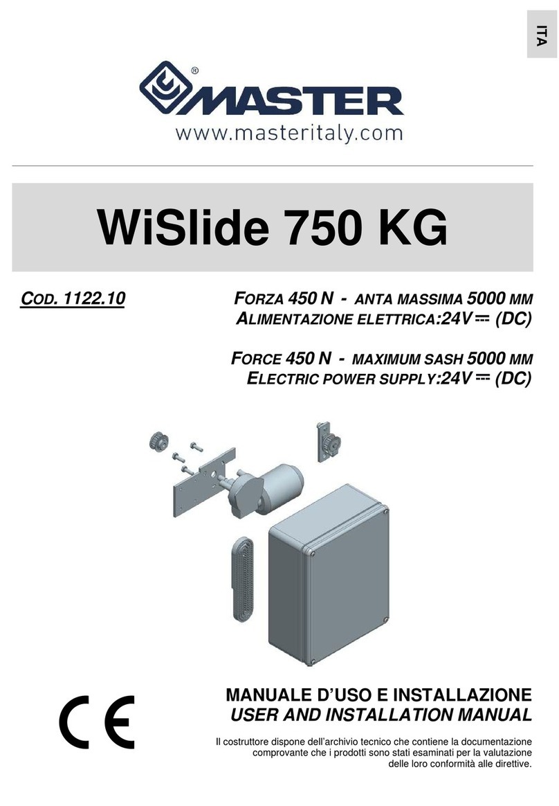
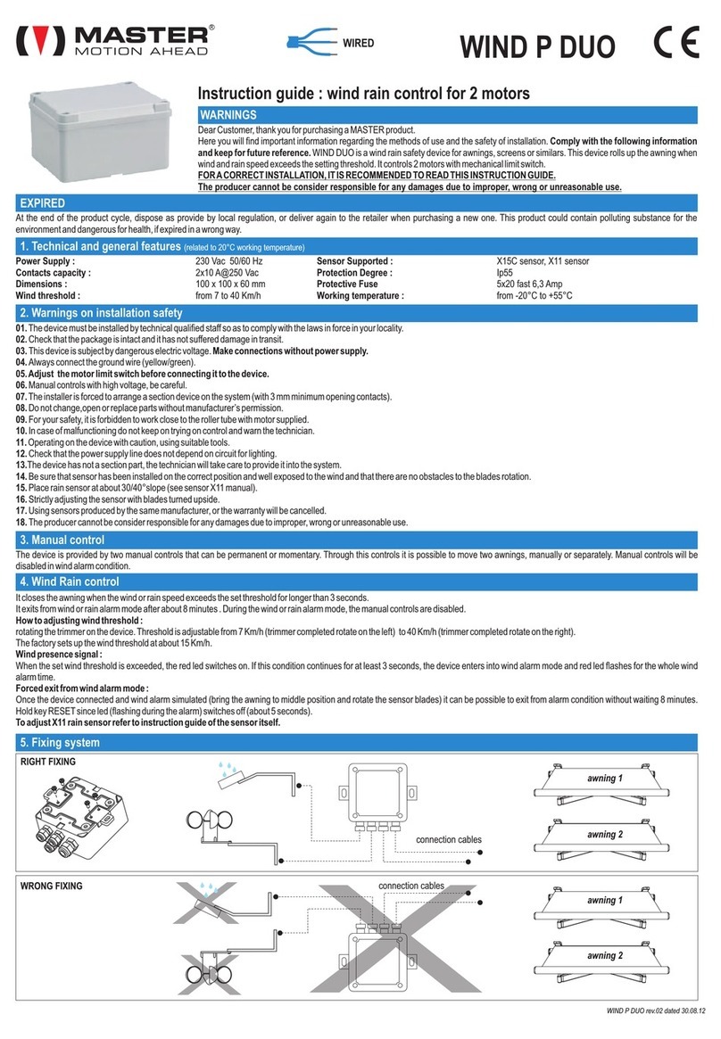
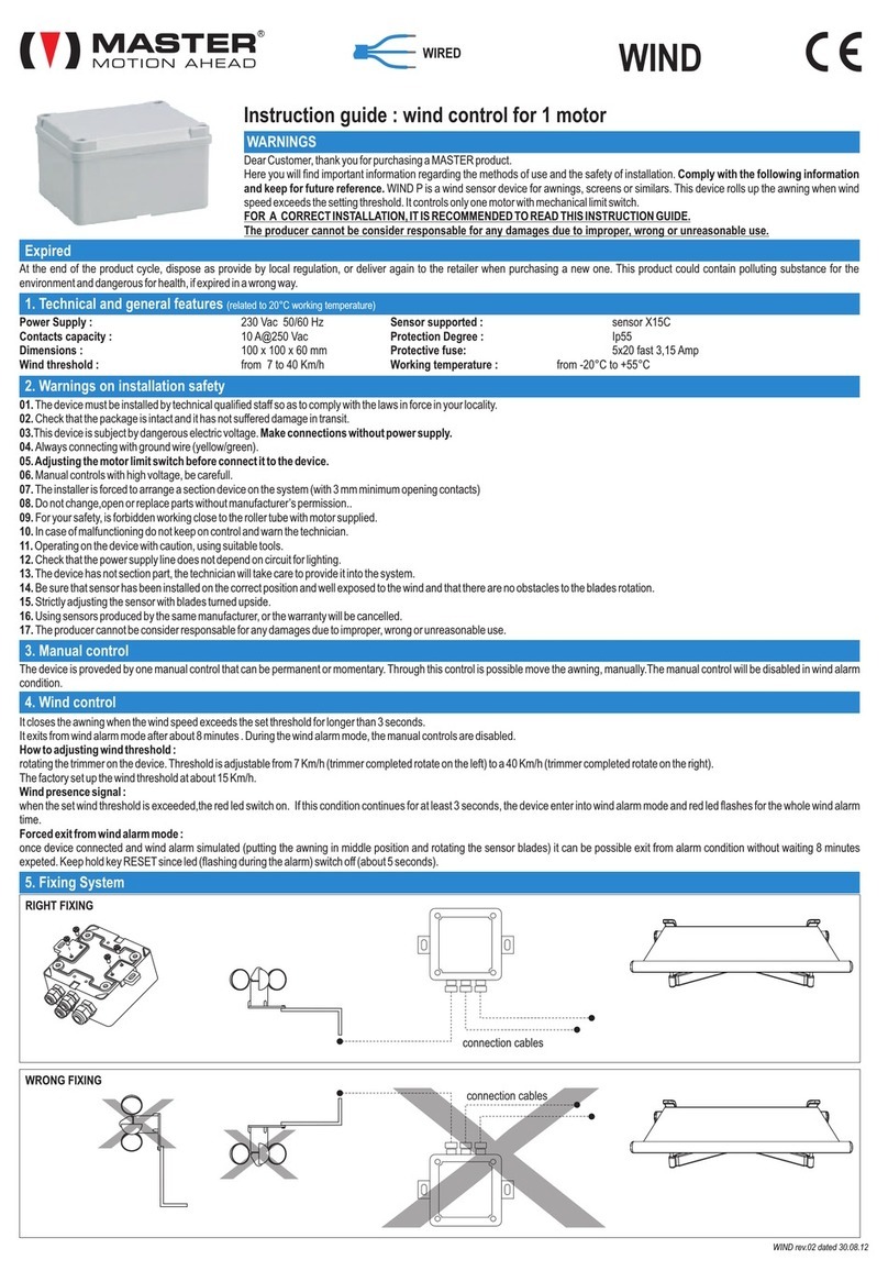
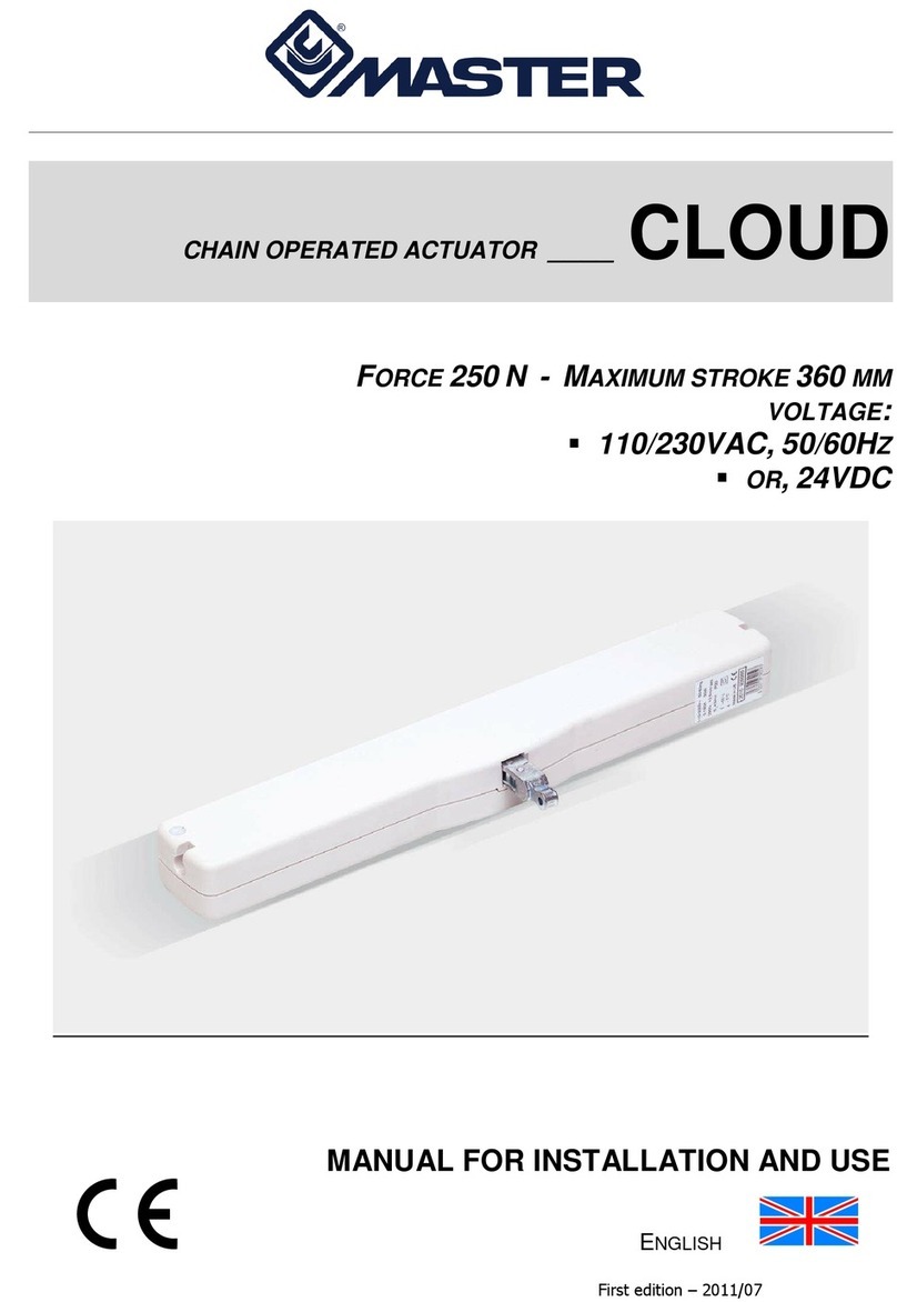
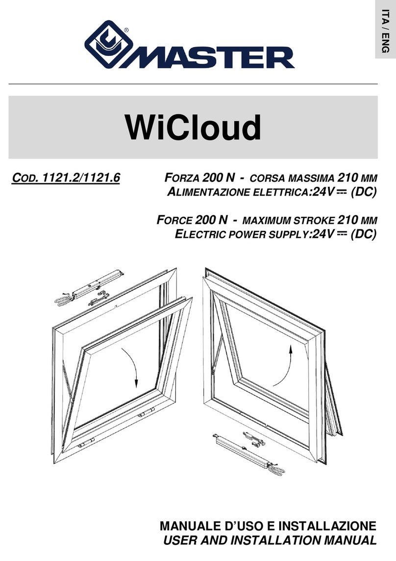
Master WiCloud 1121A.2 Operating manual

WiCloud
C
OD
.
1121A.2/1121A.6
F
ORZA
200
N
-
CORSA MASSIMA
210
MM
A
LIMENTAZIONE ELETTRICA
:24V
(DC)
F
ORCE
200
N
-
MAXIMUM STROKE
210
MM
E
LECTRIC POWER SUPPLY
:24V
(DC)
MANUALE D’USO E INSTALLAZIONE
USER AND INSTALLATION MANUAL
ITA / ENG

Pagina 2
Il costruttore dispone dell’archivio tecnico che contiene la documentazione
comprovante che i prodotti sono stati esaminati per la valutazione
delle loro conformità alle direttive.
INDICE
1. Dati tecnici..........................................................................................................................pag. 4
2. Dati di targa e marchiatura ................................................................................................pag. 4
3. Formule e consigli per l'installazione..................................................................................pag. 5
4. Costruzione e riferimenti normativi.....................................................................................pag. 5
5. Collegamento elettrico........................................................................................................pag. 5
6. Programmazione della corsa dell'attuatore.........................................................................pag. 7
Simboli usati nel manuale
PERICOLO Questa indicazione richiama l’attenzione su potenziali pericoli per
l’incolumità e la salute delle persone e degli animali.
INFORMAZIONI Le informazioni forniscono ulteriori suggerimenti.
ATTENZIONE Questa indicazione richiama l’attenzione su potenziali pericoli per il
prodotto.
AVVERTIMENTO Questa indicazione richiama l’attenzione su potenziali danni ai beni.
ISTRUZIONE
AMBIENTALE
L’istruzione ambientale richiama l’attenzione su potenziali pericoli per
l’ambiente.
Il sistema automatico WiCloud, descritto in questo manuale è destinato a movimentare
finestre a Vasistas o simili. L'uso per applicazioni diverse da quelle indicate, deve essere
autorizzato dal costruttore, previa verifica tecnica del montaggio.
ITA

Pagina 3
INDICAZIONI GENERALI PER LA SICUREZZA
ATTENZIONE Prima d’iniziare l’installazione di questa macchina, leggere attentamente e
comprendere le seguenti indicazioni di sicurezza.
L'installazione dell'apparecchio ed eventuali riparazioni devono essere eseguite da
personale tecnico competente e qualificato.
Sacchetti di plastica, polistirolo, piccole minuterie metalliche quali chiodi, graffette, ecc. non
devono essere lasciati alla portata dei bambini perché potenziali fonti di pericolo.
L’apparecchio non è destinato a essere usato da persone (bambini compresi) le cui capacità
fisiche,sensoriali o mentali siano ridotte, oppure con mancanza di esperienza o di
conoscenza, a meno che esse abbiano potuto beneficiare, attraverso l’intermediazione di
una persona responsabile della loro sicurezza, di una sorveglianza o di istruzioni riguardanti
l’uso dell’apparecchio.
Prima di collegare l'apparecchio, verificare che l'alimentazione elettrica da voi utilizzata
abbia le stesse caratteristiche indicate nell'etichetta dati tecnici, applicata all'apparecchio.
Questa macchina è destinata solo ed esclusivamente all'uso per il quale è stata concepita
ed il costruttore non può essere ritenuto responsabile per danni dovuti ad un uso improprio.
L’attuatore è destinato all’installazione interna. Per ogni applicazione speciale si raccomanda
di consultare preventivamente il costruttore.
Non lavare l’apparecchio con solventi o getti d’acqua.
Non immergere l’apparecchio in acqua.
Richiedere sempre ed esclusivamente l'impiego di ricambi originali. Il mancato rispetto di
questa regola può compromettere la sicurezza ed annulla i benefici della garanzia applicata
all'apparecchio.
Su serramenti con apertura a vasistas c’è il pericolo di lesioni prodotte dalla caduta
accidentale della finestra.
Verificare che la selezione del fine corsa permetta l’apertura della finestra senza incontrare
impedimenti di qualsivoglia natura.
L'installazione dell'apparecchio va fatta seguendo le istruzioni del costruttore. Il mancato
rispetto di tali raccomandazioni può compromettere la sicurezza. L'esecuzione dell'impianto
elettrico d’alimentazione va eseguita nel rispetto delle norme in vigore.
Pericolo di schiacciamento o di trascinamento. Durante il funzionamento, quando l’attuatore
chiude il serramento, esso esercita una forza di 200N sulle battute dell’infisso; tale pressione
è sufficiente a schiacciare le dita in caso di distrazione.
Verificare che la selezione del fine corsa sia inferiore di almeno un centimetro al bloccaggio
di fermi meccanici, limitatori di corsa oppure da eventuali impedimenti fisici all’apertura
dell’anta.
Nel caso di guasto o di mal funzionamento, spegnere l'apparecchio dall’interruttore generale
e far intervenire un tecnico qualificato.
ITA

Pagina 4
WICLOUD
1. DATI TECNICI
Modello WiCloud
Forza di spinta e trazione 200 N
Corse 70, 125, 170, 210mm
Tensione d'alimentazione 24 V
Assorbimento di corrente a carico nominale 0,32A
Potenza assorbita a carico nominale 7,5W
Velocità di traslazione a vuoto 8mm/s
Durata della corsa a vuoto (215 mm) 27 s
Tipo servizio S
2
di 3 min
Temperatura di funzionamento - 5 + 65 ºC
Grado di protezione dispositivi elettrici IP32
Funzionamento tandem Previsto
Funzionamento sincronizzato NON previsto
Forza di tenuta statica 1000N
Fine corsa in apertura Elettronico programmabile a dip-switch
Fine corsa in chiusura Ad assorbimento di potenza
Lunghezza cavo di alimentazione 2m
Uscita catena Centrale
Dimensioni 28x28x310mm
Peso apparecchio 0,660Kg
I dati tecnici riportati sopra non sono impegnativi e sono suscettibili di variazione anche senza preavviso
Scelta della sezione dei cavi d'alimentazione
2. DATI DI TARGA E MARCHIATURA
I dati di targa sono riportati in un’etichetta adesiva in polietilene, applicata all’esterno
del dispositivo. I valori sono conformi a quanto richiesto dalle norme comunitarie in
vigore. L’immagine sotto riporta un esempio di etichetta.
Sezione dei cavi Lunghezza max cavo
4,00 mm²
~ 270 m
2,50 mm²
~ 170 m
1,50 mm²
~ 100 m
0,75 mm²
~ 50 m
0,50 mm²
~ 35 m
ITA

Pagina 5
3. FORMULE E CONSIGLI PER L’INSTALLAZIONE
Calcolo della forza di apertura / chiusura
Simboli usati per il calcolo
F (Kg) = Forza apertura o chiusura P (Kg) = Peso della finestra (solo anta mobile)
C (cm) = Corsa d’apertura (corsa attuatore) H (cm) = Altezza dell’anta mobile
A
TTENZIONE
. L’attuatore è nato per essere montato ad incasso nel serramento.
Verificare che durante la corsa la catena non tocchi il profilo dell’anta, che non ci
siano ostacoli all’apertura o ci sia una forzatura della catena sul serramento.
4. COSTRUZIONE E RIFERIMENTI NORMATIVI
La struttura dell’attuatore è interamente in metallo
costruito secondo le direttive
dell'Unione Europea, è certificato in conformità con marchio .
L’impianto elettrico deve
rispettare le norme in vigore sulla progettazione e realizzazione.
5. COLLEGAMENTO ELETTRICO
L’alimentazione elettrica in bassa tensione 24V può avvenire da una centrale con batterie
di emergenza oppure con un alimentatore omologato di classe II (doppio isolamento di
sicurezza) avente tensione d’uscita di 24V (-15% ÷ +25%, cioè min. 20,4V, max. 30V).
L’alimentazione all’attuatore deve essere adeguatamente protetta da fusibili.
SPORGERE
(A)
VASISTAS
(B)
F = 0,54 x P x C : H
(Il possibile carico di vento favorevole o
contrario sull’anta, va considerato a parte).
Il dispositivo richiede una tensione di 24V . Una tensione maggiore può
distruggere il motore.
ITA

Pagina 6
Schema elettrico collegamento pulsante 6 poli
•Nero “1”, connesso al + (positivo) apre;
•Nero “2”, connesso al + (positivo) chiude;
•Nero "3", non collegare per la funzione ‘singolo’; collegare con il filo “3” dell’altro
attuatore per la funzione ‘tandem’.
Gli attuatori sono dotati di cavo di alimentazione a tre vie numerato della lunghezza di 2m
direttamente collegato. Nell'immagine in basso lo schema di collegamento dell'alimentazione
al pulsante.
Schema elettrico collegamento con relè
•Nero “1”, connesso al + (positivo) apre;
•Nero “2”, connesso al + (positivo) chiude;
•Nero "3", non collegare per la funzione ‘singolo’; collegare con il filo “3” dell’altro
attuatore per la funzione ‘tandem’.
Gli attuatori sono dotati di cavo di alimentazione a tre vie numerato della lunghezza di 2m
direttamente collegato. Nell'immagine in basso lo schema di collegamento dell'alimentazione
al pulsante.
ITA

Pagina 7
Di seguito le quote e le dimensioni in sezione dell’attuatore:
6. PROGRAMMAZIONE DELLA CORSA DELL'ATTUATORE
Fine corsa in apertura
Il fine corsa dell’attuatore in apertura, si regola con la selezione di 3 dip-switch (1, 2, 3) che si
trovano all’interno dell’attuatore sotto il tappo nero di gomma (T) (vedi fig. sotto).
Significato dei dip-switch
•Funzionamento singolo
1234
70 ON OFF OFF
125 OFF ON OFF
160 OFF OFF ON
210 OFF OFF OFF
DIP-SWITCH H anta
Max 500mm
OFF
CORSA
(mm)
Min 500mm
ITA

Pagina 8
•Funzionamento Tandem
N.B.: Nel funzionamento Tandem i due attuatori devono avere le corse settate nelle
medesime posizioni.
Nel caso in cui per errore si selezionano due o più dip-switch in ON,
l’attuatore prende la corsa più corta selezionata.
Attenzione. L’attuatore viene fornito con corsa minima 70mm.
Fine corsa in chiusura
Il fine corsa in chiusura è automatico e non programmabile.
L’arresto dell’attuatore avviene per effetto dell’assorbimento di potenza (potenza assorbita +
15% di quella nominale). Dopo ogni chiusura o intervento della protezione elettronica, la
catena si muove in senso contrario per circa 1mm, per dare la giusta compressione alle
guarnizioni e rilassare gli organi meccanici interni.
Montaggio dell’attuatore nel serramento
Prima di montare l’attuatore nel serramento verificare di:
aver fatto passare tutti i cavi necessari alle connessioni, attraverso le opportune
lavorazioni in modo da seguire il precorso ideale;
aver selezionato la corsa.
Attenzione. Verificare che non vi siano dei fili che si toccano tra loro; potrebbero
causare dei danni alle macchine del sistema.
Prima di montare l’attuatore nel serramento, collegare l’alimentazione e
programmare il fine corsa in apertura; una volta montato non è possibile agire sui
dip-switch perché sono nascosti.
ITA

Pagina 9
CONCLUSIONI
Connettere il cavo di alimentazione dell’attuatore a catena e selezionare la corsa.
Montare l’attuatore ad incasso nel foro fatto in precedenza avendo particolare cura di non
rovinare i cavi, spostandolo prima verso un lato e poi centrandolo nei fori di fissaggio.
Eseguire una prova di collaudo e verificare che il dispositivo agisca correttamente sul
serramento.
Verificare che una volta installato il prodotto, il gancio di presa dell’accessorio scorrevole
sia perfettamente agganciato quando l’attuatore è chiuso.
PROTEZIONE AMBIENTALE
Tutti i materiali utilizzati per la costruzione della macchina sono riciclabili.
Si raccomanda che la macchina stessa, accessori, imballi, ecc. siano inviati ad
un centro per il riutilizzo ecologico come stabilito dalle leggi vigenti in materia
di riciclaggio dei rifiuti.
Componenti dell’apparecchio:
Ferro Alluminio Rame Zinco Silicio Plastica
RICHIAMO AI PRINCIPI DEL CERTIFICATO DI GARANZIA
Il costruttore si rende garante del buon funzionamento della macchina. S’impegna
ad eseguire la sostituzione dei pezzi difettosi per cattiva qualità del materiale o
per difetti di costruzione secondo quanto stabilito dall’articolo 1490 del Codice
Civile.
La garanzia copre i prodotti o le singole parti per un periodo di 2 anni dalla data
d’acquisto. La stessa è valida se l’acquirente sia stato in grado di esibire la prova
d’acquisto ed abbia soddisfatto le condizioni di pagamento pattuite.
La garanzia di buon funzionamento degli apparecchi accordata dal costruttore,
s'intende nel senso che lo stesso s'impegna a riparare o sostituire gratuitamente,
nel più breve tempo possibile, quelle parti che dovessero guastarsi durante il
periodo di garanzia. L'acquirente non può vantare diritto ad alcun risarcimento per
eventuali danni, diretti o indiretti, o altre spese. Tentativi di riparazione da parte di
personale non autorizzato dal costruttore fanno decadere la garanzia.
Sono escluse dalla garanzia le parti fragili o esposte a naturale usura come pure
ad agenti o procedimenti corrosivi, a sovraccarichi anche se solo temporanei,
ecc. Il costruttore non risponde per eventuali danni causati da errato montaggio,
manovra o inserzione, da eccessive sollecitazioni o da imperizia d'uso.
Le riparazioni in garanzia sono sempre da intendersi "franco fabbrica produttore".
Le spese di trasporto relative (andata / ritorno) sono sempre a carico
dell’acquirente.
La rimozione completa o parziale dell’etichetta adesiva (riportante i dati di targa)
fa decadere la garanzia. Prima della richiesta di intervento tecnico autorizzato,
l’acquirente deve accertarsi che il cavo di alimentazione originale sia presente e
che abbia una lunghezza non inferiore a 30cm.
MASTER S.r.l. – I417I - 25/09/2017
La Master Srl non risponde in alcun modo di possibili inesattezze imputabili ad errori di stampa o di trascrizione dati nel presente foglio.
ITA

Pagina 10
The manufacturer has the technical file that contains the documentation
attesting that the products have been examined for evaluation
of their compliance with the directives.
CONTENTS
1. Technical data.......................................................................................................................page 12
2. Rating and marking ..............................................................................................................page 12
3. Formulas and recommendations for installation.......................................... .... ....................page 13
4. Construction and regulatory references................................................................................page 13
5. Electrical connection................................................................................ .............................page 13
6. Setting the stroke of the actuator...........................................................................................page 15
Symbols used in the manual
HAZARD This indication calls the reader's attention to potential hazards for the
health and well-being of people and animals.
INFORMATION The information provides further suggestions.
CAUTION This indication calls the reader's attention to potential hazards for the
product.
WARNING This indication calls the reader's attention to potential damage to
goods.
ENVIRONMENTAL
INSTRUCTION
The environmental instruction calls the reader's attention to potential
hazards for the environment.
The automatic system WiCloud described in this manual is intended to move awning/hopper
windows or the like. Any use for applications other than those indicated must be
authorized by the manufacturer upon technical verification of the assembly.
ENG

Pagina 11
GENERAL SAFETY GUIDELINES
CAUTION Before beginning to install this machine, carefully read and understand the
following safety guidelines.
The installation of the device and any repairs must be carried out by skilled and qualified
technical personnel.
Plastic bags, polystyrene, small metal parts such as nails, staples, etc. must not be left within
the reach of children as they represent potential hazards.
The device is not intended to be used by persons (including children) whose physical,
sensory or mental abilities are reduced or who lack the necessary experience or knowledge,
unless a person responsible for their safety provides supervision or instructions concerning
the use of the device.
Before connecting the device, check that the electric power supply used has the same
characteristics indicated on the technical data label, attached to the device.
This machine is intended only and exclusively for the use for which it was designed, and the
manufacturer cannot be held liable for damage due to improper use.
The actuator is designed for internal installation. For any special application, it is highly
recommended that you consult the manufacturer in advance.
Do not wash the device with solvents or water jets.
Do not submerge the device in water.
Always request the use of original spare parts only. Failure to observe this rule may
compromise safety and void the warranty applied to the device.
Hopper windows present the hazard of injuries caused by the accidental fall of the window.
Check that the selected stroke-end allows the window to open without encountering any
obstacles whatsoever.
The device must be installed following the manufacturer's instructions. Failure to observe
these recommendations may compromise safety. The electrical power supply system must
be designed and implemented in compliance with current standards.
Crushing or dragging hazard. During operation, when the actuator closes the window, it
exerts a force of 200N on the stops of the fixture; this pressure is enough to crush your
fingers in case of distraction.
Check that the selected stroke-end is at least one centimeter from mechanical stops, stroke
limiters or any physical obstacles to the opening of the sash.
In the event of a failure or malfunction, switch the device off using the power switch and call
a qualified technician.
ENG

Pagina 12
WICLOUD
1. TECHNICAL DATA
Model WiCloud
Compression and tensile force 200 N
Strokes 70, 125, 170, 210mm
Power supply voltage 24 V
Current absorbed at nominal load 0.32A
Power absorbed at nominal load 7.5W
No-load traverse speed 8mm/s
No-load stroke time (215 mm) 27 s
Service type S
2
of 3 min
Operating temperature - 5 + 65 ºC
Degree of protection for electrical devices IP32
Tandem operation Provided for
Synchronized operation NOT provided for
Static seal strength 1000N
Opening stroke-end Electronic, set by dip-switches
Closing stroke-end By power absorption
Power supply cable length 2m
Chain outlet Central
Dimensions 28x28x310mm
Device weight 0.660kg
The technical data provided above is non-binding and subject to change, even without advance notice.
Selecting the cross-section of the power supply cables
2. RATING AND MARKING
The rating data is provided on an adhesive polyethylene label attached to the
exterior of the device. The values are compliant with that required by the EC
standards in force. An example of the label is shown in the photo below.
Cable cross section Max cable length
4.00 mm²
~ 270 m
2.50 mm²
~ 170 m
1.50 mm²
~ 100 m
0.75 mm²
~ 50 m
0.50 mm²
~ 35 m
ENG

Pagina 13
3. FORMULAS AND RECOMMENDATIONS FOR INSTALLATION
Calculation of the opening / closing force
Symbols used for the calculation
F (kg) = opening or closing force P (kg) = Weight of the window (movable sash only)
C (cm) = opening stroke (actuator stroke) H (cm) = Height of the movable sash
W
ARNING
. The actuator is designed to be recess mounted on the window frame.
Check that during the stroke the chain does not touch the profile of the sash, there
are no obstacles to opening the window and the chain does not push against the
window frame.
4. CONSTRUCTION AND REGULATORY REFERENCES
The structure of the actuator is made entirely of metal,
constructed according to European
Union directives and certified in conformity with the mark.
The electrical system must
meet current standards on design and implementation.
5. ELECTRICAL CONNECTION
The 24V low-voltage electric power supply can be achieved using a station with
emergency batteries or an approved class II power supply unit (double safety insulation) with
an output voltage of 24V (-15% ÷ +25%, in other words min. 20.4V, max. 30V).
The power supply to the actuator must be suitably protected by fuses.
AWNING
(A)
HOPPER
(B)
F = 0.54 x P x C : H
(Any wind load, favorable or unfavorable on
the sash, should be considered separately).
The device requires a voltage of 24V . A higher voltage may destroy the
motor.
ENG

Pagina 14
6-pin switch connection wiring diagram
•Black “1”, connected to the + (positive) open;
•Black “2”, connected to the + (positive) close;
•Black “3”, do not connect for ‘stand alone’ operation; connect with black “3” of second
actuator for ‘Tandem’ operation.
The actuators are equipped with a numbered three-way power supply cable with a length of
2m connected directly to the device. The diagram for connecting the power supply to the
switch is provided below.
Connection wiring diagram with relay
•Black “1”, connected to the + (positive) open;
•Black “2”, connected to the + (positive) close;
•Black “3”, do not connect for ‘stand alone’ operation; connect with black “3” of second
actuator for ‘Tandem’ operation.
The actuators are equipped with a numbered three-way power supply cable with a length of
2m connected directly to the device. The diagram for connecting the power supply to the
switch is provided below.
ELECTRICAL CONNECTION WITH RELAY
ENG
ENG

Pagina 15
The diagram below specifies the length and cross-section dimensions of the actuator:
6. SETTING THE STROKE OF THE ACTUATOR
Opening stroke-end
The opening stroke-end of the actuator can be adjusted by selecting the 3 dip-switches (1, 2,
3) located inside the actuator underneath the black rubber plug (T) (see fig. below).
Meaning of the dip-switches
•‘Stand alone’ operation
1 2 3 4
70 ON OFF OFF
125 OFF ON OFF
160 OFF OFF ON
210 OFF OFF OFF
STROKE
(mm)
DIP-SWITCH H sash
OFF
Max 500mm
Min 500mm
ENG

Pagina 16
•‘Tandem’ operation
N.B.: For ‘Tandem’ operation the actuators must have the same dip-switches set.
If two or more dip-switches are accidentally set to ON, the actuator uses the
shortest of the selected strokes.
Attention. The actuator is supplied with a minimum stroke 70mm.
Closing stroke-end
The closing stroke-end is automatic and non-settable.
The stop of the actuator is determined by the power absorbed (power absorbed + 15% of the
nominal value). After each closure or intervention of the electronic protection, the chain
moves in the opposite direction by about 1mm in order to produce the right compression on
the gaskets and relax the internal mechanical parts.
Assembly of the actuator on the window frame
Before assembling the actuator on the window frame, check that:
all the cables needed for connections have been passed through the appropriate millings
so as to follow the ideal path;
the stroke has been selected.
Caution. Check that there are no wires touching one another; this could damage
the machines of the system.
Before assembling the actuator on the window frame, connect the power supply
and set the opening stroke-end; once the actuator is assembled, it is no longer
possible to operate the dip-switches since they are hidden.
ENG

Pagina 17
CONCLUSIONS
Connect the power supply cable of the chain actuator and select the stroke.
Recess mount the actuator in the hole made previously, taking particular care not to ruin
the cables, moving it first towards one side and then centering it on the fastening holes.
Perform a final test and verify that the device operates correctly on the window frame.
Check that once the product is installed, the gripping hook of the sliding accessory is
completely hooked when the actuator is closed.
ENVIRONMENTAL PROTECTION
All the materials used for construction of the machine are recyclable.
It is recommended that the machine itself, the accessories, packing materials,
etc. be sent to a recycling center as required by current laws on waste
recycling.
Components of the device:
Iron Aluminum Copper Zinc Silicon Plastic
REFERENCE TO THE PRINCIPLES OF THE WARRANTY CERTIFICATE
The manufacturer guarantees good operation of the machine. The manufacturer
also undertakes to replace pieces that are defective due to poor quality of the
material or manufacturing defects as set forth in article 1490 of the Italian Civil
Code.
The warranty covers the products or individual parts for a period of 2 years from
the date of purchase. The warranty is valid if the buyer is able to exhibit proof of
purchase and has met the agreed payment terms and conditions.
The guarantee of good operation of the devices granted by the manufacturer is
understood in the sense that the manufacturer undertakes to repair or replace,
free of charge and in the shortest time possible, those parts that have failed
during the warranty period. The buyer cannot claim right to any compensation for
any direct or indirect damages or other expenses. Any repair attempts made by
personnel who have not been authorized by the manufacturer void the warranty.
Fragile parts or parts subject to natural wear, corrosive agents or procedures,
excessive loads (even if only temporary), etc., are not covered by the warranty.
The manufacturer will not be held liable for any damage caused by incorrect
assembly, handling or insertion, excessive stress or inexperienced use.
The repairs under warranty are always understood to be "ex-factory". The buyer
must always pay the respective shipping expenses (to and from the factory).
The total or partial removing of the sticker label (with the identification code of the
article) invalidates the warranty.
Before the intervention of an authorized technician, the buyer has to prove the
presence of the original power cable, that must be no shorter than 30 cm.
MASTER S.r.l. – I417I - 25/09/2017
Master Srl may not be held liable in any way whatsoever for any inaccuracies due to printing or data transcription errors in this document
ENG

Pagina 18
NOTE:
……………………………………………………………………………………………………………………
……………………………………………………………………………………………………………………
……………………………………………………………………………………………………………………
……………………………………………………………………………………………………………………
……………………………………………………………………………………………………………………
……………………………………………………………………………………………………………………
……………………………………………………………………………………………………………………
……………………………………………………………………………………………………………………
……………………………………………………………………………………………………………………
……………………………………………………………………………………………………………………
……………………………………………………………………………………………………………………
……………………………………………………………………………………………………………………
……………………………………………………………………………………………………………………
……………………………………………………………………………………………………………………
……………………………………………………………………………………………………………………
……………………………………………………………………………………………………………………
……………………………………………………………………………………………………………………
……………………………………………………………………………………………………………………
……………………………………………………………………………………………………………………
……………………………………………………………………………………………………………………
……………………………………………………………………………………………………………………
……………………………………………………………………………………………………………………
……………………………………………………………………………………………………………………
……………………………………………………………………………………………………………………
……………………………………………………………………………………………………………………
……………………………………………………………………………………………………………………
This manual suits for next models
1
Table of contents
Languages:
Other Master Controllers manuals
Popular Controllers manuals by other brands

Vetus
Vetus SENSORD Operation manual and installation instructions

Pakedge Device & Software
Pakedge Device & Software C36-07 user manual

Bard
Bard ECU Series Supplemental instructions

YOKOGAWA
YOKOGAWA YS1700 Tech note

Emerson
Emerson REGAL 3F instruction manual

Stahl
Stahl 8602/3 Series operating instructions