Matica MC320x User manual

MC320x USER GUIDE
USER GUIDE

MC320x USER GUIDE
Copyright
Matica
June 2023
All rights reserved
Copyright Notice
Users must respect the copyright regulations applicable in their own respective countries. Photocopying,
translation, reproduction or transmission of this manual, in whole or in part, for any reason and using any
electronic or mechanical means whatsoever, without the prior written permission of the Manufacturer company
is strictly forbidden.
All contents of this manual are subject to change without prior notice.
The Manufacturer accepts no liability for any errors that may be found in this manual, or for any loss or
damage that may arise accidentally or as a result of diffusion or use of this manual.
Trademarks
All other trademarks are the property of their respective owners.
Printer Warranty
Refertothe warranty statement provided with the printer for the warranty terms andconditions, andits
limitationsofliability.
Environmental Impact
Matica is committed to reducing the environmental impact of its products through improvements in energy
efficiency.
1.
FOR COUNTRIES IN THE EUROPEAN UNION (EU)
The disposal of electric and electronic devices as solid urban waste is strictly prohibited: it must be
collected separately. The dumping of these devices at unequipped and unauthorized places may have
hazardous effects on health and the environment. Offenders will be subjected to the penalties and
measures laid down by the law.
TO DISPOSE OF OUR DEVICES CORRECTLY:
a)
Contact the Local Authorities, who will give you the practical information you need and the
instructions for handling the waste correctly, for example: location and times ofthe waste collection
centers, etc.
b)
When you purchase a new device of ours, give a used device like the one purchased to our
dealer for disposal.
The crossed dustbin symbol on the device means that:
-
When it to be disposed of, the device is to be taken tothe equipped wastecollection centers
and is to be handled separately from urban waste:
-
Matica guarantees the activation of the treatment, collection, recycling and disposal
procedures in accordance with Directive 2002/96/EC (and subsequent amendments).
2.
FOR OTHER COUNTRIES (NOT IN THE EU)
The treatment, collection, recycling and disposal of electric and electronic devices will be carried out
in accordance with the laws in force in the country in question.
DIRECTIVE 2002/96/EC ON THE TREATMENT, COLLECTION, RECYCLING AND
DISPOSAL OF ELECTRIC AND ELECTRONIC DEVICES AND THEIR COMPONENTS

MC320x USER GUIDE
For Europe
Warning
“This is a Class A product. In a domestic environment this product may cause radio interference in which
case the user may be required to take adequate measures.”
Product contains RF section (or module), compiled with ETSI EN 300 330 V2.1.1 (2017-02)
For US
This device complies with Part 15 of the FCC Rules. Operation is subject to the following two conditions:
(1) This device may not cause harmful interference, and
(2) This device must accept any interference received, including interference that may cause
undesired operation.
FCC Caution!!!
•Any changes or modification not expressly approved by the party responsible for compliance could
void the user’s authorities to operate this equipment.
This equipment has been tested and found to comply with the limits for class B digital device, pursuant to Part
15 of the FCC Rules. These limits are designed to provide reasonable protection against harmful interference
in a residential installation. This equipment generates uses and can radiate radio frequency energy and, if not
installed and used in accordance with the instructions, may cause harmful interference to radio
communications. However, there is no guarantee that interference will not occur in a particular installation. If
this equipment does cause harmful interference to radio or television reception, which can be determined by
turning the equipment off and on, the user is encouraged to try correct the interference by one or more of the
following measures:
•Reorient or relocate the receiving antenna.
•Increase the separation between the equipment and receiver.
•Connect the equipment into an outlet on a circuit different from that to which the receiver is connected.
•Consult the dealer or an experienced radio/TV technician for help.
For Canada
In English:
This device complies with Industry Canada’s license-exempt RSSs. Operation is subject to the following
two conditions:
(1)
Thisdevicemaynotcauseinterference;and
(2)
This device must accept any interference, including interference that may cause undesired operationof
thedevice.
In French :
Cet appareil est conforme aux RSS sans licence d’Industrie Canada. Son fonctionnement est soumis aux
deux conditions suivantes:
1) Cet appareil ne doit pas provoquer d'interférences; et
2) Cet appareil doit accepter toutes les interférences, y compris celles qui pourraient entraîner un mauvais
fonctionnement de l'appareil.
General Note: - This equipment must be used by –Ordinary person / Instructed person / Skilled person

MC320x USER GUIDE
About caution symbols:
These cautions indicate the risk of injury or shock or malfunction if the printer is not
operated correctly. Be sure to follow these cautions to operate the printer safely.
These cautions indicate the heated surface & involve the risk of heat injury if person
touch with bare hand.
These cautions indicate the touch of surface with bare hand is prohibited.

1 Table of Contents
2Product overview..................................................................................... 2-1
3Getting started......................................................................................... 3-1
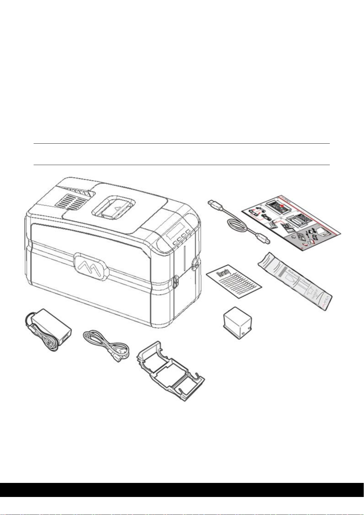
3.1 Unpacking the printer...................................................................................................... 3-2
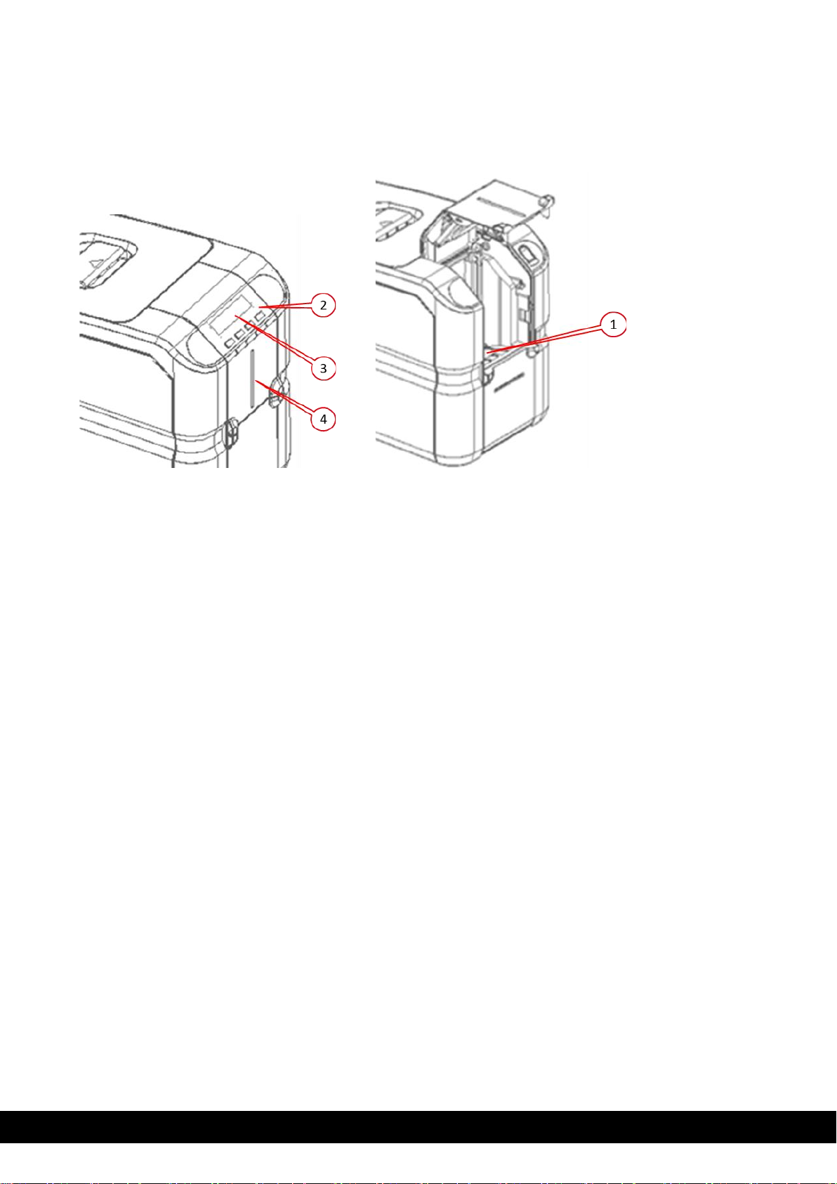
3.2 Functional description..................................................................................................... 3-3
3.2.1 Front view ........................................................................................... 3-3
3.2.2 Operator panel.................................................................................... 3-4
3.2.3 Rear view............................................................................................ 3-6
3.2.4 Power supply ...................................................................................... 3-6
3.2.5 Plastic cards........................................................................................ 3-6
4Installation procedures........................................................................... 4-1
4.1 Installing the ribbon......................................................................................................... 4-1
4.2 Rear bin installation ........................................................................................................ 4-3
4.3 Card feeding ................................................................................................................... 4-4
4.4 Input hopper (Automatic card feeder)............................................................................. 4-4
4.5 Adjusting the card thickness........................................................................................... 4-5
4.6 Connecting the power supply and powering on the printer ............................................ 4-6
5Installing the software and configuring the printer.............................. 5-1
5.1 Connecting the printer to the computer and installing the software ............................... 5-1
5.1.1 Printer connection through USB.......................................................... 5-1
5.1.2 Printer connection through LAN/ethernet............................................ 5-1
5.1.3 DCP.................................................................................................... 5-1
5.1.4 Static IP .............................................................................................. 5-7
5.2 Uninstall program tabs.................................................................................................. 5-10
5.2.1 Tools................................................................................................. 5-10
5.2.2 About ................................................................................................ 5-12
6Printing................................................................................................... 6-13
6.1 Card printing ................................................................................................................. 6-13
6.1.1 MC320x Printing preferences............................................................ 6-13
6.1.2 Print settings..................................................................................... 6-13
6.1.3 Card front settings............................................................................. 6-14
6.1.4 Card back ......................................................................................... 6-15
6.1.5 Mag encoding settings mag encoding tools ...................................... 6-15
6.2 Color settings................................................................................................................6-16
6.3 Printing test cards.........................................................................................................6-16
7Printer maintenance................................................................................ 7-1
7.1 Printer cleaning............................................................................................................... 7-1
7.2 Standard cleaning........................................................................................................... 7-1
7.3 Card path advanced cleaning......................................................................................... 7-4
7.4 Advanced cleaning ......................................................................................................... 7-4
7.5 Cleaning roller................................................................................................................. 7-5

7.5.1 Roller cleaning procedure................................................................... 7-5
7.6 Printhead cleaning.......................................................................................................... 7-7
7.6.1 Printhead cleaning procedure ............................................................. 7-7
7.7 Print head replacement................................................................................................... 7-9
7.7.1 Replacement procedure...................................................................... 7-9
8Options..................................................................................................... 8-1
8.1 Chip encoding (contact and contactless)........................................................................ 8-1
8.2 7.2 Use of PC/SC encoder tests..................................................................................... 8-1
8.3 Magnetic encoding.......................................................................................................... 8-3
8.4 Configuration................................................................................................................... 8-3
8.5 Duplex activation ............................................................................................................ 8-4
9Trouble shooting ..................................................................................... 9-1
9.1 Printer does not power on............................................................................................... 9-1
9.2 Unable to print................................................................................................................. 9-1
9.3 Ribbon errors.................................................................................................................. 9-2
9.4 Chip encoding................................................................................................................. 9-2
10 Ribbons................................................................................................ 10-1
11 Cleaning kits........................................................................................ 11-1
12 Technical characteristics.................................................................... 12-1

MC320x USER GUIDE I
3-1
2 Product overview
The printer described in this user manual provides full color dye-sublimation or monochrome thermal transfer
printing on standard 54x86 mm plastic cards. PVC, PVC Composite, PET, ABS, PC and Re-printable cards
are supported (accordingly with varnished card product configuration). It is managed from the computer
through the USB port or via Ethernet/Wi-Fi.
The ribbon carrier, that comes with the printer, allows the ribbon to be replaced quickly and easily.
Several options are available so that the printer can be configured to operate in different types of
environments:
•Magnetic stripe encoder
•Smart Card Encoding Station with Contact and Contactless Smart Card encoder.
•10/100 Ethernet connection
•Single Card Feed Option through Manual feeder
•Connection for external smart card encoding.
3 Getting started
The printer comes with several accessories; check carefully that they have all been received. This list may
vary depending on the location where the printer will be used and the configuration you have ordered.
The printer is shipped in special packaging designed to prevent damage during transportation. If any visible
damage is noticed upon reception, contact the dealer immediately.
Maintain the printer packaging intact and store it in a clean and dry place.
Note: If the printer must be returned, it must be returned integrally with its full original packaging (box,
cushions, and protective bags). If it is returned without its original packaging and any components are
damaged during transportation, such components will no longer be covered by the warranty. Matica
will also charge for the new packaging which will be required to ship the printer back.

MC320x USER GUIDE
3-2
3.1 Unpacking the printer
The following items are included in the box:
•Printer
•Quick Installation Guide
•Cleaning swab
•Cleaning card
•
Powercord
•Power supply
•USB cable
•Ribbon carrier
•Reject bin
Note: Contact the dealer immediately if any of the items listed above are missing.
Only use the power supply provided with the printer.

MC320x USER GUIDE
3-3
3.2 Functional description
3.2.1 Front view
The front of the printer is the operator side and has following features:
1)
Input Hopper
2)
Operator panel and printer status indicators: ON/OFF key and 3 functional keys
3)
LCD display

MC320x USER GUIDE
3-4
3.2.2 Operator panel
,
The front operator panel consists of 4 soft touch buttons and 4 status LEDs along with an informative display.
•Button operation
oPower button (Shown as 1)
▪Short press to turn the printer on
▪Long press to turn off the printer when it is ON
oSelection button (Shown as 2)
▪To select the menu option and transit to respective sub-menu
▪Selecting option in sub-menu. Ex. Standard Cleaning, chip encoder setting.
oMenu/Scroll button (Shown as 3)
▪Button will be used to enter in Menu.
▪Same button will be used to scroll to next menu item.
▪Same button will be used for incrementing the value while setting Sleep time.
•Status LED
oPower LED (Shown as 5)
▪White - indicates printer is ON
oStatus LED –Ready (Shown as 6)
▪Amber –indicates ribbon is nearing end.
▪Amber blinking –indicates there is no card OR no ribbon.
oStatus LED –Error (Shown as 7)
▪Red –indicates there is an error, card jam, cover open etc.
▪Red blinking –indicates printer requires servicing OR firmware upgrade.
▪Green –indicates printer is ready for printing.
▪Green blinking –indicates printer is receiving data or printing.
oWi-Fi LED –(Shown as 8)
▪Off –indicates Wi-Fi is not available.
▪Blue blinking –indicates Wi-Fi is available but not connected.
▪Blue –indicates printer is connected.
oInput hopper LED –(Shown as 9)
▪Off –indicates there is no card available.
▪Red blinking –indicates number of cards in the hopper are running low.
▪Red –indicates there are cards available in input hopper.

MC320x USER GUIDE
3-5
•LCD display sequence for the MENU option

1-4
User Guide
MC320x USER GUIDE I
3-6
3.2.3 Rear view
The following components are located on the back panel:
1)
Powercordsocket
2)
USB 2.0. female B type. Host socket
3)
Ethernet connector with traffic LED
4)
USB 2.0 port –No.1
5)
USB 2.0 port –No.2
6)
Rejection bin fixing slot
7)
Kensington lock
3.2.4 Power supply
The printer comes with an external auto-switching power supply.
Note: Only use the power supply provided with the printer.
3.2.5 Plastic cards
Listed below are the plastic card specifications:
•Type: PVC, PVC & Composite
•Dimensions: ISO CR80 - ISO 7810 (53.98 x 85.60)
•Thickness: 0.25 to 1.25 mm (10 to 50 mil) manual gaugeadjustment
•Magnetic stripe: ISO 7811
•Smart Card Contact: ISO 7816-1,2,3,4
•Smart Card Contactless: ISO 14443A/B.

MC320x USER GUIDE I
4-1
4 Installation procedures
4.1 Installing the ribbon
Original Matica ribbons are to be installed carefully. The ribbon carrier that comes with the printer helps to
install the ribbon quickly, easily, and accurately. Once the ribbon is in its carrier, the carrier can then be easily
dropped into the printer using the red and grey guides.
1) Insert the ribbon (not provided with the printer)
into the ribbon carrier by inserting the red reel to
FRONT side and grey reel to the REAR.
3)
Move the handle in the direction shown to open the top cover.

MC320x USER GUIDE I
4-2
4)
The ribbon carrier should be positioned inside the Right & Left guide cores as illustrated below.
Left guide core for ribbon carrier Right guide core for ribbon carrier
5)
Drop the ribbon carrier’s back side (trailer core) into the backend guide cores as per below instructions.

MC320x USER GUIDE I
4-3
6)
Slide the ribbon carrier’s front side (leading core) inside the front guide cores as per illustration.
7)
Now close the top cover.
Note: Ribbon carrier should be assembled without touching/damaging the printer head
4.2 Rear bin installation

MC320x USER GUIDE I
4-4
4.3 Card feeding
The input hopper (automatic card feeder) can hold a maximum of one hundred 0.76 mm thick cards. A label
inside the door gives clear instructions for correctly positioning and orienting the card.
When the single card manual feeder option is present, it can be used without needing to empty the input
hopper.
The card path can be selected via the software to increase card processing speed:
•Hopper
•
Reject bin
The output hopper at the front of the printer can hold a maximum of thirty 0.76 mm thick cards.
4.4 Input hopper (Automatic card feeder)
1. Open the front door manually as shown below.
2. Load the cards into the hopper and close the door.
Card insertion
direction
For contact type
cards, chip will be
visible on the top.
Mag stripe will be
facing downwards
towards the right.

MC320x USER GUIDE I
4-5
4.5 Adjusting the card thickness
The card thickness can be adjusted by sliding the selection knob (A label is attached on the encoder cover
to guide the selection knob) to the required thickness.
Cards with thicknesses ranging between 0.25 mm and 1.25 mm (10 - 50 mil) can be processed by the
printer. Proceed as follows to adjust the card thickness:
1) Open the top cover as per the instructions below.
2)
Slide the card thickness selection knob to match the card thickness.
3)
Close the top cover.

MC320x USER GUIDE I
4-6
4.6 Connecting the power supply and powering on the printer
Connect the power cord to the power outlet (a) tothe power supply and then connect the power supply to
the printer (b)asshownbelow. PresstheON/OFFbutton (c)topowerontheprinter.

User Guide
3-1
MC320x USER GUIDE I
5-1
5 Installing the software and configuring the printer
The XPS driver can be accessed via the link here: https://www.maticagroup.com/products/mc320x/ or
stated on the quick start guide. The link will provide you with the following downloads:
•Windows 7, 8,8.1,10,11 (32 and 64 bit), Server 2016, 2019, 2022 printer driver for USB, Ethernet
LAN and Wireless connections (if supported by the purchased model)
•PDF UserGuide
•Driver Installer (XPS DRIVER)
5.1 Connecting the printer to the computer and installing the software
5.1.1 Printer connection through USB
1) Download/ save a copy of MC320x driver software onto your PC/Laptop.
2) Double click on the Matica XPS driver installer.exe application to setup the wizard.
3) Click ´Next´.

3-2
User Guide
MC320x USER GUIDE I
5-2
4)Select “I accept the agreement” to accept the license agreement and click ‘Next’.
5) In case you want to Install the printer using LAN connection tick the box ‘Add a printer connected through
the network’and Click ‘Next’to continue with the installation.
For USB connection leave the option unticked & click ‘Next’to continue with the installation.
This manual suits for next models
1
Table of contents
Other Matica Printer manuals