EN
User Manual
measurement mode. To turn it o, turn it back to the
OFF position.
HOLD Button
• Data hold function. By pressing briey, the currently
measured value is recorded on the display. With the
second press, we can return to the measurement mode.
B/L Button
• Turn backlight on/o. Bypressingthe button, thebacklight
can be turned on and remains on for ~30 seconds, while
the measurement result can be safely read. In order to
protect the battery that ensures the long-term operation
of the device, the backlight turns o automatically.
• Attention: For battery with low energy level, this
function does not work for energy saving reasons.
MeasUreMent
Voltage measurement
• Set the function selector switch
~
mode.
• By pressing the SELECT key, select the type of voltage
to be measured (DC or AC voltage).
• Connect the black test lead to the COM jack and the red
test lead to the V Live˚C˚Fjack.
• Connect the other end of the test leads to the circuit or
source to be measured.
• Read the measured value from the display. The polarity
of the red test lead is shown on the display when
measuring DC voltage (only the negative sign).
• ATTENTION: If you are not sure of the approximate
value of the measured value, set the instrument to the
maximum measurement limit. To avoid electric shock
and damage to the device, never exceed the 1000 V DC
or 750 V AC RMS voltage limit!
• V.F.C measurement (low-pass lter):
• In this measurement mode, the instrument only
measures the AC voltage between 50-200Hz, thus
eliminating the measurement inaccuracy that can
be caused by high-frequency voltage components
entering the electrical network..
• Pressing the SELECT button for a long time switches to
V.F.C. for measurement.
• LowZ measurement:
• In this measurement mode, the input of the instrument
switches to low-impedance mode, thus eliminating
from the measurement those voltage components
that were introduced into the network due to various
disturbances. Set the dial to the“LowZ”position.
• WARNING: in this mode, the instrument can be used
up to 300 V AC.
Resistance measurement
• Set the function selector switch to the position.
• Connect the black test lead to the COM jack and the red
test lead to the V Live˚C˚Fjack.
• Connect the test leads to the two terminals of the resistor.
• Read the measured value from the display.
• Note: In the measurement range of 10 MΩ, the device
needs a few seconds for a stable measurement.
• If the measured circuit exceeds the maximum
measurement limit, the display shows OL.
• ATTENTION: If you are not sure of the approximate
value of the measured value, then set the instrument
to the maximum measurement limit or automatic
measurement limit mode. In order to avoid damage to
the device or electric shock, cut o the external power
source of the circuit to be measured, or turn o the
high-power capacitors!
Continuity, tensile test
• Set the function selector to position.
• Press the FUNC button to select the function.
• Connect the black test lead to COM and the red test
lead to V Live˚C˚F.
• Connect the other ends of the test leads to the circuit
under test. If the resistance between the two points is less
than 30 Ω, the device indicates this with a beeping sound.
• Note: the continuity test is also good for looking at the
open/closed state of a circuit.
• ATTENTION: In order to avoid damage to the device
or electric shock, cut off the external power source
of the circuit to be measured, or turn off the high-
power capacitors!
Diode measurement
• Set the function selector to position.
• Press the SELECT button to select the function.
• Connect the black test lead to COM, and the red test
lead toV Live˚C˚F.
• Touch the red lead to the diode’s anode and the black
lead to its cathode.
• The opening voltage of the diode will be read on the
display. If the polarity is accidentally reversed, the OL
icon will appear on the display.
• ATTENTION: In order to avoid damage to the device
or electric shock, cut off the external power source
of the circuit to be measured, or turn off the high-
power capacitors!
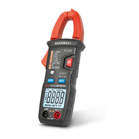
Current measurement
• Set the function selector to the
A
~
position and
switch to the AC position with the SELECT button.
• Press the trigger to release the jaws and capture
the guide in the closed area. Make sure the jaws are
properly closed.The measured value can be read on the
display. Before measuring, if the value on the display
does not reset, press the ZERO button.
• INR function (starting current measurement):
• Peak currents can be measured in this measurement
mode, e.g. When starting AC motors, the sampling
frequency of the instrument is high in this function. In
the AC current measurement function, long press the
INR button.
• Note: Let’s measure one conductor at a time!
• The values of the phase and neutral wire running in one
cable cancel each other out, the measured value will be 0!
• Do not touch the measured conductor with your hands,
even if you are sure that it is perfectly insulated.
