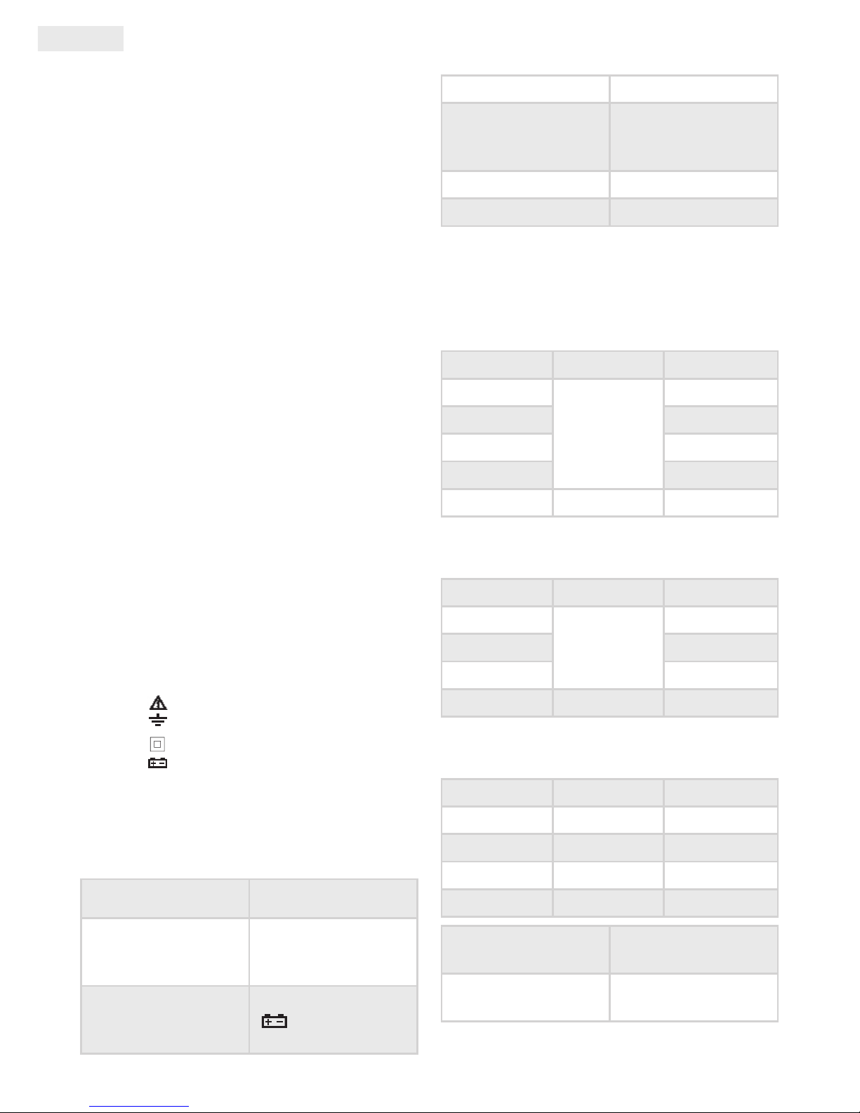
Maxwell 25201 User manual

User ManUal
anwendUngsinforMation
Használati Utasítás
ManUal de Utilizare
Užívateľská prírUčka
DIGITAL MULTIMETER
DIGITALMULTIMETER
DIGITÁLIS MULTIMÉTER
MULTIMETRU DIGITAL
DIGITÁLNY MULTIMETER
Product code / Produktcode / Termékkód / Cod produs / Kód produkta:
25201
EN
DE
HU
RO
SK
i
VC890C+

EN User Manual
sUMMary
This broad-spectrum measurement device
enables you to measure DCV, ACV, DCA, ACA,
resistance, capacity, diode, transistor, continuity
and temperature. Ideal for using in laboratories,
factories and even at home.
safety reMarks
This device complies to the IEC10101 standards.
Read the manual carefully before use.
• Do not measure a higher value than the set
range.
• To avoid electric shock make sure that the
measuring wires are intact.
• Disconnect the measuring wires while
changing function.
• Select the proper function and range, avoid
incorrect usage.
• Do not use the device if the battery holder lid
and back cover are not in their places.
• Do not measure voltage while in resistance
measuring mode.
• Remove the wires and turn the device o
before replacing the battery or fuse.
• Safety signs:
Dangerous voltage
Grounding
Double insulation
Low battery power
CHaraCteristiCs
Display LCD display
Max. value display:
1999 (3 ½ digit)
automatic polarity
display
Low battery power
display
Operating
environment (0-40) °C, R. H. 80%.
Battery
9V X 1 (NEDA
1604/6F22 or same
type)
Dimensions 170 X 90 X 55mm
Weight 350g (with battery)
teCHniCal data
DCV
Range Accuracy Resolution
200mV
±0.5%
100μV
2V 1mV
20V 10mV
200V 100mV
1000V ±0.8% 1V
ACV
Range Accuracy Resolution
2V
±0.8%
1mV
20V 10mV
200V 100mV
750V ±1.2% 1V
DCA
Range Accuracy Resolution
200μA ±2.0% 100nA
20mA ±1.5% 10μA
200mA ±1.5% 100μA
20A ±1.5% 10mA
Max. inward current
20A (testing time
should be 10 sec
max)
Fuse 0,2A/250V and 20A /
250 V fast fuse

User Manual EN
ACA
Range Accuracy Resolution
20mA ±(1.5%+5) 10μA
200mA 100μA
20A ±(3.0%+10) 10mA
Max. inward current
20A (testing time
should be 10 sec
max)
Fuse 0,2A/250V and 20A /
250 V fast fuse
Resistance
Range Accuracy Resolution
200Ω ±0.8% 0.1Ω
2kΩ
±0.8%
1Ω
20kΩ 10Ω
200kΩ 100Ω
2MΩ 1kΩ
20MΩ ±1.2% 10kΩ
WARNING:
Do not measure voltage while in resistance
mode!
Capacity
Range Accuracy Resolution
20nF
±2.5%
1pF
200nF 100pF
20μF 10nF
200μF ±5.0% 100nF
Measuring frequency 150 Hz
Overload protection 36 V DC / AC RMS
Temperature
Range Accuracy Resolution
(-40~1000)°C < 400°C±0,8%
> 400°C±1,5% 1°C
with a K type temperature sensor
Diode and continuity test
Function Description Test state
Opening voltage
Positive DC
voltage
appr. 1mA
negative volt-
age appr. 3V
Beeping if the re-
sistance is lower
than (70±20)Ω
Opening volt-
age appr. 3V
Triode hFE test
Function Description Test state
hFE NPN
or PNP 0~1000
Opening
voltage appr.
10μA
Opening
voltage appr.
3V
operation
1. Model no.
2. LCD display
3. Diode signal light
4. Function switch
5. „+”connector : 20A
6. „+”connector : mA+ capacity +
temperature
7. „-”connector: ground (GND) + capacity+
temperature
8. „+”connector: voltage, resistance, diode,
continuity test
9. Transistor connector
MX-25 201
AUTO POWER OFF
NPN
E B C E
E B C E
PNP
Ù
V
V
~
A
~
VÙ
20A
mA COM
A
F
OFF hFE
200mV
2V
20V
200V
1000V
750V
200V
20V
2V
20m
200m
20A
20A
200m
20m
200u
2u
°C
20n
200u
200
2k
20k
200k
20M
Cx/°C
CAT II
MAX
200mA
FUSED
MAX
1000VDC
750V AC
10secMAX
20A
UNFUSED

EN User Manual
DCV measuring
• Connect the black measuring wire to the
„COM”connector, and the red one to the„V/Ω”
connector.
• Set the function switch to the proper DCV
setting, and connect the wires to the circuit.
Note:
• If you are unsure about the measured voltage range, set
the function switch to a high range.
• If the LCD shows „1”it means overload, and the range
should be set to a higher value.
ACV measuring
• Connect the black measuring wire to the
„COM”connector, and the red one to the„V/Ω”
connector.
• Set the function switch to the proper ACV
setting and connect the wires to the circuit.
Note:
• If you are unsure about the measured voltage range, set
the function switch to a high range.
• If the LCD shows „1”it means overload, and the range
should be set to a higher value.
DCA measuring
• Connect the black measuring wire to the
„COM”connector, and the red one to the„mA”
connector (max. 200mA), or connect the red
wire to the„20A” connector (max. 20A).
• Set the function switch to the proper DCA
setting and connect the wires to the circuit.
Note:
• If you are unsure about the measured voltage range, set
the function switch to a high range.
• If the LCD shows „1”it means overload, and the range
should be set to a higher value.
• Max inward current 200mA or 20A (depending on the
placement of the red wire), in case of an exceeding
current the fuse will melt.
ACA measuring
• Connect the black measuring wire to the
„COM”connector, and the red one to the„V/Ω”
connector.
• Set the function switch to the proper ACA
setting, and connect the wires to the circuit.
Note:
• If you are unsure about the measured voltage range, set
the function switch to a high range.
• If the LCD shows „1”it means overload, and the range
should be set to a higher value.
• Max inward current 1000V.
Resistance measuring
• Connect the black measuring wire to the
„COM”connector and the red one to the V/Ω
connector.
• Set the function switch to the proper
resistance setting and connect the wires to the
measured resistor.
Note:
• If the measured resistance value is over the chosen max
value the LCD will show„1”and the function switch
needs to be set to a higher range. It may take a few
seconds for the device to stabilize when measuring
above 1M
Capacity measuring
• Connect the wire to the„V/Ω„ connector and
the red one to the„COM” connector.
• Set the function switch to a proper capacity
setting and connect the wires to the measured
capacitor.
Note:
• If you are unsure about the measured capacity set the
function switch to a high range.
• If the LCD shows„1”it means overload and the function
switch needs to be set to a higher range.
• To be safe, discharge the measured capacitor before
measuring.
Diode and continuity test
• Connect the black measuring wire to the
„COM”connector, and the red one to the„V/Ω”
connector (Note: the red wire's polarity is„+”)
• Set the function switch to the„ ”position,
connect the wires to the measured diode.
• Connect the wires to the diode's measuring
points, if the device beeps, the resistance is
lower than appr. (70±20)Ω
Temperature measuring
• Connect the red wire to the mA, and the black
one to the "COM" connector. Touch the end
of the thermometer to the measured object
and the temperature value is displayed on the
screen in degrees Celsius.
hFE
• Set the function switch to hFE.
• Place the part into the transistor connector
depending on whether it is NPN or PNP type.
Automatic turn-o
• If the device is not used for 15 minutes it turns
o automatically. To use it again, turn the
function switch.

User Manual EN
MaintenanCe
• Note that this device is not water-, dust- and
shock-resistant.
• Do not use and do not store the device at high
temperatures, in places with high humidity or
ammability or in strong magnetic elds.
• Do not use rough textile or alcohol.
• If the device is not being used for a longer
time period, the battery must be taken out.
Battery replacement (1 x 9V)
If the LCD display shows„ ”, the battery
needs to be replaced the following way:
• Take the device out of the plastic holder and
take o the battery holder cover.
• Take out the battery and replace it to a new
one. Use alkaline batteries if possible.
• Put the battery holder cover back.
Fuse replacement
• Only used the prescribed types of fuses for
replacing.
If the device does not operate properly,
check the following:
State Solution
Nothing is displayed
• Device is turned
o
• Replace the
battery
„”is displayed Replace the battery
No power Replace the fuse

DE Anwendungsinformation
zUsaMMenfassUng
Das Messgerät ermöglicht es Ihnen,daß Sie DCV,
ACV, DCA, ACA, Widerstand, Kapazität, Diode,
Transistor, Kontinuität und Temperatur können
messen. Es ist ideal für Labore,
Fabriken und auch zu Hause.
siCHerHeitsHinweise
Das Messgerät entspricht die Standards
IEC1010. Vor der Benutzung leses Sie
aufmerksam die Anwendungsinformation.
• Messen Sie nicht einen größeren Wert bei dem
eingestellten Messbereich.
• Um Stromschläge zu vermeiden, benutzen
Sie das Gerät nicht, wenn die Messleitungen
beschädigt sind.
• Trennen Sie die Messleitungen beim
Funktionswechsel.
• Wählen Sie die richtige Funktion und
Messbereich aus, vermeiden Sie die falsche
Verwendungen.
• Verwenden Sie nicht das Messgerät, wenn der
Deckel und die Rückseite des Batteriehalters
nicht auf Ihren Plätzen sind.
• Messen Sie keine Spannung, während im
Widerstand Meßmodus.
• Entfernen Sie die Kabel und schalten Sie das
Gerät vor dem Auswechseln der Batterie oder
der Sicherungen aus.
• Sicherheitszeichen:
Gefährliche Spannung
Erdung
Doppelisolierung
Niedrige Akku
paraMetern
Anzeiger LCD
Max. Anzeige:
1999 (3 ½ digit) mit
automatisch Polarität
Anzeige
Niedrige Akku
Anzeige
Betriebsumgebung (0-40) °C, R. H. 80%.
Batterie
9V X 1 (NEDA
1604/6F22 oder
ebensolcher Typ)
Größe 170 X 90 X 55mm
Gewicht 350g (mit Batterie)
teCHnisCHe daten
DCV
Messbereich Genauigkeit Auösung
200mV
±0.5%
100μV
2V 1mV
20V 10mV
200V 100mV
1000V ±0.8% 1V
ACV
Messbereich Genauigkeit Auösung
2V
±0.8%
1mV
20V 10mV
200V 100mV
750V ±1.2% 1V
DCA
Messbereich Genauigkeit Auösung
200μA ±2.0% 100nA
20mA ±1.5% 10μA
200mA ±1.5% 100μA
20A ±1.5% 10mA
Max. Eingangs-
Stromstärke
20A (Testzeit sollte 10
sec. max)
Sicherung
0,2A/250V und
20A / 250 V quick
Sicherung

Anwendungsinformation DE
ACA
Messbereich Genauigkeit Auösung
20mA ±(1.5%+5) 10μA
200mA 100μA
20A ±(3.0%+10) 10mA
Max. Eingangs-
Stromstärke
20A (Testzeit sollte 10
sec. max)
Sicherung
0,2A/250V und
20A / 250 V quick
Sicherung
Widerstand
Messbereich Genauigkeit Auösung
200Ω ±0.8% 0.1Ω
2kΩ
±0.8%
1Ω
20kΩ 10Ω
200kΩ 100Ω
2MΩ 1kΩ
20MΩ ±1.2% 10kΩ
WARNUNG:
Messen Sie keine Spannung, während im
Widerstand Meßmodus!
Kapazität
Messbereich Genauigkeit Auösung
20nF
±2.5%
1pF
200nF 100pF
20μF 10nF
200μF ±5.0% 100nF
Frequenzmessung 150 Hz
Überlastungsschutz 36 V DC / AC RMS
Temperatur
Messbereich Genauigkeit Auösung
(-40~1000)°C < 400°C±0,8%
> 400°C±1,5% 1°C
mit Typ-K Temperaturfühler
Diode und Kontinuität Test
Funktion Beschreibung Test Zustand
Leerlaufspan-
nung
Der positive DC
Stromstärke
ca. 1mA, Die
negative Span-
nung ca. 3V
Eingebaut
Piepser
signalisiert,
wenn der
gemessene
Widerstand
unter (70±20)
Ω ist.
Leerlaufspan-
nung ca. 3V
Triode hFE Test
Funktion Beschreibung Test Zustand
hFE NPN
oder PNP 0~1000
Leerlauf-
stromstärke
ca. 10μA
Leerlaufspan-
nung ca. 3V
BetrieB
1. Model Nummer
2. LCD Anzeiger
3. Diode Warnlicht
4. Funktions-Wahlschalter
5. „+”Eingangsbuchse : 20A
6. „+”Eingangsbuchse : mA+ Kapazität +
Temperatur
7. „-”Eingangsbuchse : Erdung (GND) +
Kapazität+ Temperatur
MX-25 201
AUTO POWER OFF
NPN
E B C E
E B C E
PNP
Ù
V
V
~
A
~
VÙ
20A
mA COM
A
F
OFF hFE
200mV
2V
20V
200V
1000V
750V
200V
20V
2V
20m
200m
20A
20A
200m
20m
200u
2u
°C
20n
200u
200
2k
20k
200k
20M
Cx/°C
CAT II
MAX
200mA
FUSED
MAX
1000VDC
750V AC
10secMAX
20A
UNFUSED

DE Anwendungsinformation
8. „+”Eingangsbuchse : Spannung,
Widerstand, Diode, kontinuität Test
9. Transistor Einfassung
DCV Messung
• Verbinden Sie die schwarze Messleitung mit
dem COM-Anschluss und die rote Messleitung
mit dem„V/Ω”-Anschluss.
• Stellen Sie den Funktions-Wahlschalter in
die gewünschte DCV Einstellung ein, dann
verbinden Sie die Messleitungen mit dem zu
messenden Stromkreis.
Hinweis:
• Wenn Sie nicht sicher über die gemessene Spannung
Wert ist, stellen Sie die Funktions-Wahlschalter in ein
höheres Stadium.
• Wenn das LCD Display zeigt„1”, bedeutet es zu größem
Wert und müssen Sie die Funktions-Wahlschalter in ein
höheres Stadium stellen.
ACV Messung
• Verbinden Sie die schwarze Messleitung mit
dem COM-Anschluss und die rote Messleitung
mit dem„V/Ω”-Anschluss.
• Stellen Sie den Funktions-Wahlschalter in
die gewünschte ACV Einstellung ein, dann
verbinden Sie die Messleitungen mit dem zu
messenden Stromkreis.
Hinweis:
• Wenn Sie nicht sicher über die gemessene Spannung
Wert ist, stellen Sie die Funktions-Wahlschalter in ein
höheres Stadium.
• Wenn das LCD Display zeigt„1”, bedeutet es zu größem
Wert und müssen Sie die Funktions-Wahlschalter in ein
höheres Stadium stellen.
DCA Messung
• Verbinden Sie die schwarze Messleitung mit
dem COM-Anschluss und die rote Messleitung
mit dem„mA” Anschluss (max. 200mA), oder
verbinden Sie die rote Messleitung mit dem
„20A” Anschluss (max. 20A).
• Stellen Sie den Funktions-Wahlschalter in
die gewünschte DCA Einstellung ein, dann
verbinden Sie die Messleitungen mit dem zu
messenden Stromkreis.
Hinweis:
• Wenn Sie nicht sicher über die gemessene Spannung
Wert ist, stellen Sie die Funktions-Wahlschalter in ein
höheres Stadium.
• Wenn das LCD Display zeigt„1”, bedeutet es zu größem
Wert und müssen Sie die Funktions-Wahlschalter in ein
höheres Stadium stellen.
• Max. Eingangs-Stromstärke 200mA oder 20A (es hängt
davon, wohin Sie die rote Messleitung verbinden),
Im Falle einem übermäßigen Stromstärke wird die
Sicherung abschmelzen..
ACA Messung
• Verbinden Sie die schwarze Messleitung mit
dem COM-Anschluss und die rote Messleitung
mit dem„V/Ω”-Anschluss.
• Stellen Sie den Funktions-Wahlschalter in
die gewünschte ACA Einstellung ein, dann
verbinden Sie die Messleitungen mit dem zu
messenden Stromkreis
Hinweis:
• Wenn Sie nicht sicher über die gemessene Spannung
Wert ist, stellen Sie die Funktions-Wahlschalter in ein
höheres Stadium.
• Wenn das LCD Display zeigt„1”, bedeutet es zu größem
Wert und müssen Sie die Funktions-Wahlschalter in ein
höheres Stadium stellen.
• Max. Eingangs-Spannung 1000V.
Widerstandmessung
• Verbinden Sie die schwarze Messleitung mit
dem COM-Anschluss und die rote Messleitung
mit dem„V/Ω”-Anschluss.
• Stellen Sie den Funktions-Wahlschalter in die
gewünschte Widerstand ein, dann verbinden
Sie die Messleitungen mit dem zu messenden
Widerstand
Hinweis:
• Wenn der gemessene Widerstand größer als der
gewählte maximale Wert, zeigt das LCD Display „1”
, bedeutet es zu größem Wert und müssen Sie die
Funktions-Wahlschalter in ein höheres Stadium stellen.
• Wenn der Widerstand über 1M ist, dann das Gerät
kann einige Sekunden dauern, zu stabilisieren.
Kapazitätmessung
• Verbinden Sie die schwarze Messleitung mit
dem COM-Anschluss und die rote Messleitung
mit dem„V/Ω”-Anschluss.
• Stellen Sie den Funktions-Wahlschalter in die
gewünschte Kapazität ein, dann verbinden Sie
die Messleitungen mit dem Kondensator.
Hinweis:
• Wenn Sie nicht sicher über die gemessene Kapazität
Wert ist, stellen Sie die Funktions-Wahlschalter in ein
höheres Stadium.
• Wenn das LCD Display zeigt„1”, bedeutet es zu größem
Wert und müssen Sie die Funktions-Wahlschalter in ein
höheres Stadium stellen.
• Vor der Messung der Kapazität entladen Sie den
Kondensator.

Anwendungsinformation DE
Diode und Kontinuität Test
• Verbinden Sie die schwarze Messleitung mit
dem COM-Anschluss und die rote Messleitung
mit dem„V/Ω”-Anschluss. (Hinweis: Polarität
der roten Messleitung:„+”)
• Stellen Sie den Funktions-Wahlschalter in die„
”Einstellung ein, dann verbinden Sie die
Messleitungen mit der zu messenden Diode.
• Verbinden Sie die Messleitungen mit zwei
Punkte des Ersatzteiles, wenn der gemessene
Widerstand unter (70±20)Ω ist, das gerät wird
signalisieren.
Temperaturmessung
• Verbinden Sie die schwarze Messleitung
mit dem COM-Anschluss und die rote
Messleitung mit dem mA-Anschluss. Ende des
Thermometers berühren Sie zu gemessenem
Objekt, dann können Sie die Temperatur-Wert
aus der LCD in Celsius ablesen.
hFE
• Stellen Sie den Funktions-Wahlschalter in die
hFE Position.
• Kontrollieren Sie, dass der Transistor NPN oder
PNP Typ ist und platzieren Sie den Ersatzteil in
die Einfassung des Transistors.
Automatisch Auschaltung
• Die automatische Ausschaltung ist nach
ca. 15 Minuten aktivieren. Wenn Sie das
Gerät neustarten möchten, drehen Sie den
Funktions-Wahlschalter.
wartUng
• Beachten Sie, dass dieses Gerät nicht wasser-,
staub-und stoßfest.
• Verwenden Sie nicht und lagern Sie nicht das
Gerät bei hohen Temperaturen, in Orten mit
hoher Luftfeuchtigkeit und Entzündlichkeit
oder in starken Magnetfeldern. Verwenden Sie
keine groben Tuch und Alkohol.
• Wenn das Gerät nicht für eine lange Zeit
funktioniert, sollten sie die Batterie entfernen.
Batterieaustausch (1 Stück 9V Batterie)
Wenn das LCD Display zeigt „ ” , dann müssen
Sie die Batterie in folgender Weise austauschen:
• Nehmen Sie das Gerät aus dem Plastikgehäuse
aus und entnehmen Sie den Batteriehalter
• Nehmen Sie die Batterie aus und ersetzen
Sie, um eine neue. Verwenden Sie dauerhafte
Batterie.
• Fixieren Sie den Batteriehalter und nehmen Sie
das Plastikgehäuse zurück.
Sicherungsaustausch
• Verwenden Sie der vorgeschriebenen Arten
von Sicherungen zu ersetzen.
Wenn das Gerät nicht richtig funktioniert,
dann kontrollieren Sie auf folgende Weise:
Zustand Lösung
Keine Anzeige
• Das Gerät ist
ausgeschaltet
• Tauschen Sie die
Batterie aus
erscheint„ ”
Symbol
Tauschen Sie die
Batterie aus
Kein Strom Tauschen Sie die
Sicherung aus

HU Használati utasítás
Összegzés
A műszer széleskörű használata lehetővé teszi
DCV, ACV, DCA, ACA, ellenállás, kapacitás, dióda,
tranzisztor, folytonossági teszt és hőmérséklet
mérését. Használata ideális laboratóriumokban,
gyárakban és otthon is.
Biztonsági Megjegyzés
A mérőműszer az IEC1010 szabványoknak
megfelel. Használat előtt gyelmesen olvassa el
a használati utasítást.
• Ne mérjen nagyobb értéket a beállított
méréshatárnál.
• Az elektromos áramütés elkerülése miatt
ellenőrizze, hogy a műszerzsinórok sérülés
mentesek legyenek.
• Helyezze át a műszerzsinórokat funkció
váltásakor.
• Válassza ki a helyes funkciót és méréshatárt,
kerülje el a hibás műveleteket.
• Ne használja a mérőműszert, ha az elemtartó
fedele és a hátlapja nincs a helyére rögzítve.
• Ellenállásmérés állásban ne mérjen
feszültséget.
• Húzza ki a vezetékeket és kapcsolja ki a
műszert, mielőtt kicseréli az elemet vagy a
biztosítékot.
• Biztonsági jelzések:
Fennáló veszélyes feszültség
Föld
Dupla szigetelés
Gyenge akkumulátor
jelleMzők
Kijelző LCD kijelzés
Max. kijelzés:
1999 (3 ½ digites)
automatikus polaritás
kijelzéssel
Gyenge
akkumulátor
kijelzés
Működési környezet (0-40) °C, R. H. 80%.
Elem
9V X 1 (NEDA
1604/6F22 vagy
ugyanolyan típusú)
Méret 170 X 90 X 55mm
Tömeg 350g (elemmel)
Műszaki adatok
DCV
Méréshatár Pontosság Felbontás
200mV
±0.5%
100μV
2V 1mV
20V 10mV
200V 100mV
1000V ±0.8% 1V
ACV
Méréshatár Pontosság Felbontás
2V
±0.8%
1mV
20V 10mV
200V 100mV
750V ±1.2% 1V
DCA
Méréshatár Pontosság Felbontás
200μA ±2.0% 100nA
20mA ±1.5% 10μA
200mA ±1.5% 100μA
20A ±1.5% 10mA
Max. bemeneti
áramerősség
20A (a tesztidő
max.10 mp legyen)
Bizosíték 0,2A/250V és 20A /
250 V gyorsbiztosíték

Használati utasítás HU
ACA
Méréshatár Pontosság Felbontás
20mA ±(1.5%+5) 10μA
200mA 100μA
20A ±(3.0%+10) 10mA
Max. bemeneti
áramerősség
20A (a tesztidő
max.10 másodperc
legyen)
Bizosíték 0,2A/250V és 20A /
250 V gyorsbiztosíték
Ellenállás
Méréshatár Pontosság Felbontás
200Ω ±0.8% 0.1Ω
2kΩ
±0.8%
1Ω
20kΩ 10Ω
200kΩ 100Ω
2MΩ 1kΩ
20MΩ ±1.2% 10kΩ
FIGYELMEZTETÉS:
Ellenállás méréskor feszültséget ne mérjen!
Kapacitás
Méréshatár Pontosság Felbontás
20nF
±2.5%
1pF
200nF 100pF
20μF 10nF
200μF ±5.0% 100nF
Mérési frekvencia 150 Hz
Túlterhelés elleni
védelem 36 V DC / AC RMS
Hőmérséklet
Méréshatár Pontosság Felbontás
(-40~1000)°C < 400°C±0,8%
> 400°C±1,5% 1°C
K típusú hőmérsékletmérő szenzorral
Dióda és folytonossági teszt
Funkció Leírás Teszt állapot
Nyító feszültség
A pozitív DC
áramerősség
kb. 1mA a
negatív feszült-
ség kb. 3V
Csipogó, ha az
ellenállás
kevesebb, mint
(70±20)Ω
Nyitott feszült-
ség kb. 3V
Trióda hFE teszt
Funkció Leírás Teszt állapot
hFE NPN
vagy PNP 0~1000
Nyitó
áramerősség
kb. 10μA
Nyitó feszült-
ség kb. 3V
MűkÖdés
1. Model szám
2. LCD kijelző
3. Dióda jelzőfény
4. Funkció kapcsoló
5. „+”bemeneti aljzat : 20A
6. „+”bemeneti aljzat : mA+ kapacitás +
hőmérséklet
7. „-”bemeneti aljzat : föld (GND) + kapacitás
+ hőmérséklet
8. „+”bemeneti aljzat : feszültség, ellenállás,
dióda, folyonosság teszt
9. Tranzisztor foglalat
MX-25 201
AUTO POWER OFF
NPN
E B C E
E B C E
PNP
Ù
V
V
~
A
~
VÙ
20A
mA COM
A
F
OFF hFE
200mV
2V
20V
200V
1000V
750V
200V
20V
2V
20m
200m
20A
20A
200m
20m
200u
2u
°C
20n
200u
200
2k
20k
200k
20M
Cx/°C
CAT II
MAX
200mA
FUSED
MAX
1000VDC
750V AC
10secMAX
20A
UNFUSED

HU Használati utasítás
DCV mérése
• Helyezze be a fekete műszerzsinórt a„COM”
aljzatba, a pirosat pedig a„V/Ω”aljzatba.
• Állítsa be a funkciókapcsolót a megfelelő DCV
fokozatba, csatlakoztassa a műszerzsinórokat
az áramkörhöz.
Megjegyzés:
• Ha nem biztos a mérendő feszültség értékében, állítsa a
funkciókapcsolót magasabb mérési fokozatba.
• Ha az LCD„1”-et mutat, ez túl nagy értéket jelent, és a
funkciókapcsolót egy magasabb fokozatba kell állítani.
ACV mérése
• Helyezze be a fekete műszerzsinórt a„COM”
aljzatba, a pirosat pedig a„V/Ω”aljzatba.
• Állítsa a funkciókapcsolót a megfelelő
ACV mérési fokozatba, csatlakoztassa a
műszerzsinórokat az áramkörhöz.
Megjegyzés:
• Ha nem biztos a mérendő feszültség értékében, állítsa a
funkciókapcsolót magasabb mérési fokozatba.
• Ha az LCD„1”-et mutat, ez túl nagy értéket jelent, és a
funkciókapcsolót egy magasabb fokozatba kell állítani.
DCA mérése
• Helyezze be a fekete műszerzsinórt a„COM”
aljzatba, a pirosat pedig az„mA” aljzatba (max.
200mA), vagy helyezze a piros műszerzsinórt a
„20A” aljzatba (max. 20A).
• Állítsa be a funkciókapcsolót a megfelelő DCA
fokozatba, csatlakoztassa a műszerzsinórokat
az áramkörhöz.
Megjegyzés:
• Ha nem biztos a mérendő áramerősség értékében,
állítsa a funkciókapcsolót magasabb mérési fokozatba
• Ha az LCD„1”-et mutat, ez túl magas értéket jelent, és a
funkciókapcsolót egy magasabb fokozatba kell állítani.
• Max. bemeneti áramerősség 200mA vagy 20A (attól
függ, hová van a piros műszerzsinór behelyezve), túlzott
áramerősség esetén kiolvad a biztosíték.
ACA mérése
• Helyezze be a fekete műszerzsinórt a„COM”
aljzatba, a pirosat pedig a„V/Ω”aljzatba.
• Állítsa be a funkciókapcsolót egy
megfelelő ACA fokozatba, csatlakoztassa a
műszerzsinórokat az áramkörhöz.
Megjegyzés:
• Ha nem biztos a mérendő feszültség értékében, állítsa a
funkciókapcsolót magasabb mérési fokozatba
• Ha az LCD„1”-et mutat, ez túl magas értéket jelent, és a
funkciókapcsolót egy magasabb fokozatba kell állítani.
• Max. bemeneti feszültség 1000V.
Ellenállás mérése
• Helyezze be a fekete műszerzsinórt a„COM”
aljzatba, a pirosat pedig a V/Ω aljzatba.
• Állítsa be a funkciókapcsolót egy megfelelő
ellenállás fokozatba, csatlakoztassa a
műszerzsinórokat a mérendő ellenálláshoz.
Megjegyzés:
• Ha mért ellenállás értéke túllép a kiválasztott maximum
értéken, az LCD„1”-et mutat, így a funkciókapcsolót egy
magasabb fokozatba kell állítani. Amikor az ellenállás
1M felett van, akkor a műszernek eltarthat néhány
másodpercig a stabilizálás.
Kapacitás mérése
• Helyezze a műszerzsinórt a„V/Ω„ csatlakozó
aljzatba, és a feketét pedig a„COM” aljzatba.
• Állítsa a funkciókapcsolót egy megfelelő
kapacitású fokozatba, csatlakoztassa a
műszerzsinórokat a mérendő kondenzátorhoz.
Megjegyzés:
• Ha nem biztos a mérendő kapacitás értékében, állítsa a
funkciókapcsolót magasabb mérési fokozatba
• Ha az LCD„1”-et mutat, ez túl magas értéket jelent, és a
funkciókapcsolót egy magasabb fokozatba kell állítani.
• Kapacitás mérése előtt a biztonság kedvéért a mérendő
kondenzátort süsse ki
Dióda és folytonossági teszt
• Helyezze a fekete műszerzsinórt a„COM”
aljzatba, a pirosat pedig a„V/Ω”aljzatba.
(Megjegyzés: a piros műszerzsinór polaritása:
„+”)
• Állítsa a funkciókapcsolót„ ”fokozatba,
csatlakoztassa a műszerzsinórokat a mérendő
diódára.
• Csatlakoztassa a műszerzsinórokat az alkatrész
két pontjához, ha a műszer sípol, akkor az
ellenállás kisebb, mint kb. (70±20)Ω
Hőmérséklet mérése
• Helyezze a piros mérőzsinórt a mA , a
feketét pedig a COM bemeneti aljzatba. A
hőmérő véget érintse a mérendő tárgyhoz, a
hőmérséklet értékét le lehet olvasni az LCD-ről
Celsiusban.
hFE
• Állítsa a funkciókapcsolót hFE-be.
• Helyezze az alkatrészt a tranzisztor foglalatba
ügyelve arra, hogy NPN vagy PNP fajta.

Használati utasítás HU
Automatikus kikapcsolás
• Ha a műszert 15 percig nem használjuk, akkor
automatikusan kikapcsol. Az újraindításhoz
forgassa el a funkciókapcsolót.
karBantartás
• Vegye gyelembe, hogy a műszer nem vízálló,
porálló és ütésálló.
• Ne használja és ne tárolja a műszert magas
hőmérsékleten, nagy páratartalmú és
lobbanékony helyen, vagy erős mágneses
területen.
• Ne használjon érdes ruhát és alkoholt.
• Ha a műszer sokáig nem működik, akkor ki kell
venni az elemet.
Elemcsere (1 db 9V-os)
Ha az LCD kijelző„ ”-t mutat, akkor ki kell
cserélni az elemet az alábbi módon:
• Vegye ki a műanyag tokból és vegye le az
elemtartót.
• Vegye ki az elemet, és cserélje ki egy újra.
Használjon tartós elemet.
• Rögzítse az elemtartót, és tegye vissza a
műanyag tokot
Biztosítékcsere
• Biztosíték kicserélésére csak az előírt típust
használja.
Ha a műszer nem megfelelően működik,
akkor az alábbi módon ellenőrizze a műszert
Állapot Megoldás
Nincs kijelzés
• Ki van kapcsolva
a műszer
• Cserélje ki az
elemet
„”jelenik meg Cserélje ki az elemet
Nem kap áramot Cserélje ki a
biztosítékot

RO Manual de utilizare
rezUMat
Deoarece instrumentul este de gamă largă
îl putem utiliza la măsurare DCV, ACV, DCA,
ACA, rezistenţă, capacitate, diode, tranzistoare,
continuitate şi temperatură. Utilizarea lui este
ideal în laboratoare, fabrici şi chiar acasă.
notă de sigUranţă
Instrumentul îndeplineşte standardele IEC1010.
Citiţi cu atenţie instrucţiunile de utilizare înainte
de folosire.
• Nu măsuraţi valoare mai mare decât domeniul
de măsurat stabilit.
• Pentru evitarea electrocutării vericaţi
cablurile de măsurat să nu e vătămaţi.
• Când schimbaţi funcţia aşezaţi cablurile de
măsurat la contactul potrivit funcţiei.
• Alegeţi funcţia şi domeniul de măsurat corect,
evitaţi operaţiunile greşite.
• Nu utilizaţi instrumentul dacă capacul
compartimentului bateriei şi capacul din spate
nu sunt xate la loc.
• În modul de măsurare rezistenţă nu măsuraţi
tensiune.
• Îndepărtaţi cablurile de măsurat şi opriţi
instrumentul înainte să schimbaţi bateria sau
fuzibilul.
• Marcaje de siguranţă:
Prezenţa tensiunii periculoase
Masă
Izolaţie dublă
Baterie descărcată
proprietăţi
Aşaj Aşaj LCD
Aşare maximă:
1999 (3 ½ cifre) cu
indicarea polarităţii
automatică
Indicare baterie
descărcată
Ambianţă de lucru (0-40) °C, R. H. 80%.
Baterie
1buc 9V (NEDA
1604/6F22 sau de
acelaşi tip)
Mărime 170 x 90 x 55mm
Greutate 350g (cu baterie)
date teHniCe
DCV
Domeniu de
măsurat Acurateţe Rezoluţie
200mV
±0.5%
100μV
2V 1mV
20V 10mV
200V 100mV
1000V ±0.8% 1V
ACV
Domeniu de
măsurat Acurateţe Rezoluţie
2V
±0.8%
1mV
20V 10mV
200V 100mV
750V ±1.2% 1V
DCA
Domeniu de
măsurat Acurateţe Rezoluţie
200μA ±2.0% 100nA
20mA ±1.5% 10μA
200mA ±1.5% 100μA
20A ±1.5% 10mA
Curent max. de
intrare
20A (timpul de test
max.10sec să e)
Fuzibil 0,2A/250V şi 20A /
250 V fuzibil rapid

Manual de utilizare RO
ACA
Domeniu de
măsurat Acurateţe Rezoluţie
20mA ±(1.5%+5) 10μA
200mA 100μA
20A ±(3.0%+10) 10mA
Curent max. de
intrare
20A (timpul de test
max.10sec să e)
Fuzibil 0,2A/250V şi 20A /
250 V fuzibil rapid
Rezistenţă
Domeniu de
măsurat Acurateţe Rezoluţie
200Ω ±0.8% 0.1Ω
2kΩ
±0.8%
1Ω
20kΩ 10Ω
200kΩ 100Ω
2MΩ 1kΩ
20MΩ ±1.2% 10kΩ
ATENŢIE: La modul de măsurare rezistenţă nu
măsuraţi tensiune!
Capacitate
Domeniu de
măsurat Acurateţe Rezoluţie
20nF
±2.5%
1pF
200nF 100pF
20μF 10nF
200μF ±5.0% 100nF
Frecvenţa de măsurat 150 Hz
Protecţie împotriva
suprasarcinii 36 V DC / AC RMS
Temperatură
Domeniu de
măsurat Acurateţe Rezoluţie
(-40~1000)°C < 400°C±0,8%
> 400°C±1,5% 1°C
Cu termocuplă de tip K
Test de diode şi continuitate
Funcţie Descriere Stare test
Tensiune de
deschidere
Curentul
pozitiv DC cca.
1mA, tensiunea
negativă cca.
3V
Piuie dacă
rezistenţa este
mai mică de
(70±20)Ω
Tensiunea
deschisă cca.
3V
Test triodă hFE
Funcţie Descriere Stare test
hFE NPN
sau PNP 0~1000
Curent de
deschidere
cca. 10μA
Tensiune de
deschidere
cca. 3V
fUnCţionare
1. Nr model
2. Aşaj LCD
3. Lumină indicatoare diodă
4. Comutator funcţii
5. „„+”banană de intrare : 20A
6. „+”banană de intrare : mA+ condensator +
temperatură
7. „-”banană de intrare : masă (GND) +
condensator + temperatură
8. „+”banană de intrare : tensiune, rezistenţă,
diodă, test de continuitate
9. Soclu tranzistor
MX-25 201
AUTO POWER OFF
NPN
E B C E
E B C E
PNP
Ù
V
V
~
A
~
VÙ
20A
mA COM
A
F
OFF hFE
200mV
2V
20V
200V
1000V
750V
200V
20V
2V
20m
200m
20A
20A
200m
20m
200u
2u
°C
20n
200u
200
2k
20k
200k
20M
Cx/°C
CAT II
MAX
200mA
FUSED
MAX
1000VDC
750V AC
10secMAX
20A
UNFUSED

RO Manual de utilizare
Măsurare DCV
• Aşezaţi cablul de măsurat negru la„COM” iar
cel roşu la„V/Ω”.
• Rotiţi comutatorul de funcţii la domeniul
potrivit DCV, conectaţi cablurile de măsurat la
circuit.
Notă:
• Dacă nu sunteţi sigur în valoarea tensiunii ce va
măsurat, aşezaţi comutatorul de funcţii la un domeniu
superior.
• Dacă aşajul LCD arată„1”înseamnă că valoarea este
prea mare şi trebuie să comutaţi comutatorul de funcţii
la un domeniu mai mare.
Măsurare ACV
• Aşezaţi cablul de măsurat negru la„COM” iar
cel roşu la„V/Ω”.
• Rotiţi comutatorul de funcţii la domeniul
potrivit ACV, conectaţi cablurile de măsurat la
circuit.
Notă:
• Dacă nu sunteţi sigur în valoarea tensiunii ce va
măsurat, aşezaţi comutatorul de funcţii la un domeniu
superior.
• Dacă aşajul LCD arată„1”înseamnă că valoarea este
prea mare şi trebuie să comutaţi comutatorul de funcţii
la un domeniu mai mare.
Măsurare DCA
• Aşezaţi cablul de măsurat negru la„COM” iar
cel roşu la„mA” (max. 200mA) sau la„20A”
(max. 20A).
• Rotiţi comutatorul de funcţii la domeniul
potrivit DCA, conectaţi cablurile de măsurat la
circuit.
Notă:
• Dacă nu sunteţi sigur în valoarea curentului ce va
măsurat, aşezaţi comutatorul de funcţii la un domeniu
superior.
• Dacă aşajul LCD arată„1”înseamnă că valoarea este
prea mare şi trebuie să comutaţi comutatorul de funcţii
la un domeniu mai mare.
• Curentul maxim de intrare 200mA sau 20A (în funcţie
de unde este conectat cablul roşu de măsurat), în caz de
curent exagerat se topeşte fuzibilul
Măsurare ACA
• Aşezaţi cablul de măsurat negru la„COM” iar
cel roşu la„V/Ω”.
• Rotiţi comutatorul de funcţii la domeniul
potrivit ACA, conectaţi cablurile de măsurat la
circuit.
Notă:
• Dacă nu sunteţi sigur în valoarea curentului ce va
măsurat, aşezaţi comutatorul de funcţii la un domeniu
superior.
• Dacă aşajul LCD arată„1”înseamnă că valoarea este
prea mare şi trebuie să comutaţi comutatorul de funcţii
la un domeniu mai mare.
• Curentul maxim de intrare 200mA sau 20A (în funcţie
de unde este conectat cablul roşu de măsurat), în caz de
curent exagerat se topeşte fuzibilul.
• Tensiunea maximă este 1000V
Măsurare rezistenţă
• Aşezaţi cablul de măsurat negru la„COM” iar
cel roşu la„V/Ω”.
• Rotiţi comutatorul de funcţii la domeniul
potrivit de rezistenţă, conectaţi cablurile de
măsurat la rezistor.
Notă:
• Dacă valoarea rezistorului depăşeşte domeniul ales,
aşorul LCD va indica„1”. Comutatorul de funcţii trebuie
să aşezaţi la un domeniu superior. Când rezistorul are
valoare peste 1M instrumentul va avea nevoie câteva
secunde până la stabilire
Măsurare capacitate
• Aşezaţi cablul de măsurat negru la„COM” iar
cel roşu la„V/Ω”.
• Rotiţi comutatorul de funcţii la domeniul
potrivit de capacitate, conectaţi cablurile de
măsurat la condensator.
Notă:
• Dacă nu sunteţi sigur de valoarea condensatorului
aşezaţi comutatorul de funcţii la un domeniu de măsurat
superior
• Dacă aşorul LCD indică„1” aveţi valoare prea mare şi
comutatorul de funcţii trebuie să mutaţi la un domeniu
de măsurat mai mare.
• Înainte de măsurare capacitate pentru siguranţă
descărcaţi condensatorul ce doriţi să măsuraţi
Test de diodă şi continuitate
• Aşezaţi cablul de măsurat negru la„COM” iar
cel roşu la„V/Ω”. (Notă: polaritatea cablului de
măsurat roşu este:„+”)
• Rotiţi comutatorul de funcţii la„ ”,
conectaţi cablurile de măsurat la dioda ce
măsuraţi.
• Conectaţi cablurile de măsurat la circuitul
testat. Dacă instrumentul piuie rezistenţa
circuitului este mai mică de cca. (70±20)Ω
Măsurare temperatură
• Aşezaţi cablul de măsurat negru la„COM” iar
cel roşu la mA. Vârful termocuplei atingeţi la
obiectul testat. Temperatura se poate citi de pe
aşajul LCD în grade Celsius

Manual de utilizare RO
hFE
• Rotiţi comutatorul de funcţii la poziţia hFE.
• Aşezaţi componentul în soclul de tranzistor
având grijă la tipul lui NPN sau PNP.
Oprire automată
• Dacă instrumentul nu folosiţi timp de 15
minute, se opreşte automat. Pentru repornire
rotiţi comutatorul de funcţii.
Întreţinere
• Ţineţi cont de faptul că instrumentul nu e
rezistent la apă, praf şi lovituri.
• Nu utilizaţi şi nu depozitaţi instrumentul la
temperaturi ridicate, la umiditate relativă
ridicată şi locuri inamabile sau loc puternic
magnetizat.
• Nu utilizaţi cârpă dură şi spirt.
• Dacă instrumentul nu funcţionează timp
îndelungat trebuie să scoateţi bateria
Schimbarea bateriei (1 buc tip 9V)
Dacă aşajul LCD indică„ ” trebuie să
schimbaţi bateria în felul următor:
• Scoateţi din husa din plastic şi demontaţi
capacul compartimentului bateriei.
• Scoateţi bateria şi schimbaţi cu unul nou.
Folosiţi baterie durabilă.
• Fixaţi compartimentul bateriei şi asamblaţi
înapoi husa din plastic.
Schimbarea siguranţei
• Pentru schimbarea fuzibilului folosiţi doar tipul
specicat
Dacă instrumentul nu funcţionează corect
vericaţi instrumentul în felul următor
Stare Soluţie
Nu este aşare
• Instrumentul
este oprit
• Schimbaţi
bateria
„”apare pe aşaj Schimbaţi bateria
Nu primeşte curent Schimbaţi siguranţa

SK Uživateľská príručka
preHľad
Rozsiahle využívanie prístroja dá možnosť na
meranie odporu, DCV, ACV, DCA, ACA, kapacity,
diódy, tranzistora, testu kontinuity a teploty.
Ideálne použitie v laboratóriumoch , továrni a v
dome.
Bezpečnostné poznáMky
Prístroj splňa normy IEC1010 . Pred používanie
si prečítajte návod na použitie pozorne.
• Nemerajte väčšiu hodnotu, ako je nastavený
merací limit.
• Aby sa zabránilo elektrického šoku, kontrolujte
šnúry prístroja, či sú v dobrom stave.
• Presuňte šnúry prístroja u prepnuitie funkcií.
• Vyberte správnú funkciu a meracíeho limita a
vyhnite si chybných operácií.
• Nepoužite prístroj, ak predný a zadný panel
držiaka batérií nie je dobre uzavretý.
• Nemerajte napätie v polohe meranie odporu.
• Vyťiahnite káble, a vypnite prístroj pred
výmenu batérií alebo poistok.
• Bezpečnostné označenie:
Nebezpečné napätie
Pôda
Dvojitá izolácia
Slabý akumulátor
fUnkCie
Displej LCD displej
Max. zobrazenie:
1999 (3 ½ digitový)
s automatickým
zobrazením polarity
Zobrazenie slabého
akumulátora
Prevádzkové
prostredie (0-40) °C, R. H. 80%.
Batéria
9V X 1 (NEDA
1604/6F22 alebo taký
istý typ)
Rozmery 170 X 90 X 55mm
Váha 350g (s batériou)
teCHniCké údaje
DCV
Merací rozsah Presnosť Rozlíšenie
200mV
±0.5%
100μV
2V 1mV
20V 10mV
200V 100mV
1000V ±0.8% 1V
ACV
Merací rozsah Presnosť Rozlíšenie
2V
±0.8%
1mV
20V 10mV
200V 100mV
750V ±1.2% 1V
DCA
Merací rozsah Presnosť Rozlíšenie
200μA ±2.0% 100nA
20mA ±1.5% 10μA
200mA ±1.5% 100μA
20A ±1.5% 10mA
Max. vstupná sila
prúdu
20A (doba testovanie
max.10 s)
Poistka 0,2A/250V a 20A /
250 V rýchlo poistka
ACA
Merací rozsah Presnosť Rozlíšenie
20mA ±(1.5%+5) 10μA
200mA 100μA
20A ±(3.0%+10) 10mA
Max. vstupná sila
prúdu
20A (doba testovanie
max.10 s)

Uživateľská príručka SK
Poistka 0,2A/250V a 20A /
250 V rýchlo poistka
Odpor
Merací rozsah Presnosť Rozlíšenie
200Ω ±0.8% 0.1Ω
2kΩ
±0.8%
1Ω
20kΩ 10Ω
200kΩ 100Ω
2MΩ 1kΩ
20MΩ ±1.2% 10kΩ
UPOZORNENIE:
Nemerajte napätie u meranie opdoru!
Kapacita
Merací rozsah Presnosť Rozlíšenie
20nF
±2.5%
1pF
200nF 100pF
20μF 10nF
200μF ±5.0% 100nF
Meracia frekvencia 150 Hz
Ochrana proti
preťaženiu 36 V DC / AC RMS
Teplota
Merací rozsah Presnosť Rozlíšenie
(-40~1000)°C < 400°C±0,8%
> 400°C±1,5% 1°C
So senzorom teplomeru typu K
Test diódy a kontinuity
Funkcia Opis Testovací stav
Počiatočné
napätie
Pozitívna
sila prúdu
DC o. 1mA
a negatívné
napätie o. 3V
Pípanie, ak odpor
je menej, ako
(70±20)Ω
Počiatočné
napätie o. 3V
Test Triódy hFE
Funkcia Opis Testovací
stav
hFE NPN
alebo PNP 0~1000
Počiatočná
sila prúdu
o. 10μA
Počiatočné
napätie o. 3V
prevádzka
1. Číslo modelu
2. LCD displej
3. Diódové signalizačné svetlo
4. Spínač funkcií
5. „+”vstupná zásuvka : 20A
6. „+”vstupná zásuvka : mA+ kapacita +
teplota
7. „-”vstupná zásuvka : pôda (GND) +
kapacita + teplota
8. „+”vstupná zásuvka : napätie, odpor, dióda,
test continuity,
9. Tranzistorová zásuvka
DCV meranie
• Vložte čierne šnúry prístroja do zásuvky „COM”,
a červené do zásvuky„V/Ω”.
• Nastavte spínača funkcií na správnej
úrovni,DCV a pripojte šnúry prístroja k obvodu.
Poznámka:
• Ak nie ste istý v hodnote meraného napätia, nastavte
spínača funkcií na vyššý merací úroveň.
• Ak LCD zobrazí nápis„1”, to znamená prílliš veľkú
hodnotu, vtedy si musíte nastaviť spínača funckií do
vyššej úrovni
MX-25 201
AUTO POWER OFF
NPN
E B C E
E B C E
PNP
Ù
V
V
~
A
~
VÙ
20A
mA COM
A
F
OFF hFE
200mV
2V
20V
200V
1000V
750V
200V
20V
2V
20m
200m
20A
20A
200m
20m
200u
2u
°C
20n
200u
200
2k
20k
200k
20M
Cx/°C
CAT II
MAX
200mA
FUSED
MAX
1000VDC
750V AC
10secMAX
20A
UNFUSED

SK Uživateľská príručka
ACV meranie
• Vložte čierne šnúry prístroja do zásuvky„COM”,
a červené do zásuvky „V/Ω”.
• Nastavte spínača funckií na správnej meraciej
úrovni ACV, a pripojte šnúry prístroja k obvodu
Poznámka:
• Ak nie ste istý v hodnote meraného napätia, nastavte
spínača funkcií na vyššý merací úroveň.
• Ak LCD zobrazí nápis„1”, to znamená prílliš veľkú
hodnotu, vtedy si musíte nastaviť spínača funckií do
vyššej úrovni.
DCA meranie
• Vložte čierne šnúry prístroja do zásvuky „COM”
, a červené do zásuvky „mA” (max. 200mA),
alebo vložte červené šnúry prístroja do
zásuvky„20A”(max. 20A).
• Nastavte spínača funckií na vhodnej úrovni
DCA, pripojte šnúry prístroja k obvode.
Poznámka:
• Ak nie ste istý v hodnote meraného silu prúdu, nastavte
spínača funkciu na vyššý merací úroveň.
• Ak LCD zobrazí nápis „1”,to znamená príliš vysokú
hodnotu, a vtedy musíte nastaviť spínača funkcií do
vyššej úrovni.
• Max. vstupná sila prúdu je 200mA alebo 20A (závisí
od toho, kde je červená šnúra prístroja pripojená), u
prípade príliš veľkej silu prúdu poistka sa rozpúšťí
ACA meranie
• Vložte čierne šnúry prístroja do zásuvky „COM”,
a červené do zásvuky„V/Ω”.
• Nastavte spínača funkcií do správnej
úrovni,ACA a pripojte šnúry prístroja k obvodu.
Poznámka:
• Ak nie ste istý v hodnote meraného napätia, nastavte
spínača funkcií na vyššý merací úroveň.
• Ak LCD zobrazí nápis„1”, to znamená príliš veľkú
hodnotu, vtedy musíte nastaviť spínača funckií do
vyššej úrovni.
• Max. vstupné napätie 1000V
Meranie odporu
• Vložte čierne šnúry prístroja do zásuvky „COM”,
a červené do zásvuky„V/Ω”.
• Nastavte spínača funkcií do vhodnej úrovni
odporu a pripojte šnúry prístroja k meraného
odporu.
Poznámka:
• Ak nameraná hodnota prestúpí na vybrané maimálnu
hodnotu, LCD zobrazí nápis„1”, vtedy spínača funkcií
si musite nastaviť na vyššý úroveň. Ak odpor je nad
1M, tak prístroj potrebuje niekoľkých minút na
stabilizovanie.
Meranie kapacít
• Vložte čierne šnúry prístroja do zásuvky „COM”,
a červené do zásvuky„V/Ω”.
• Vložte šnúry prístroja do konektorovej zásuvky
„V/Ω , a čierne do zásuvky „COM”.
• Nastavte spínača funkcií na úrovni s vhodnou
kapacitou, a pripojte šnúry prístroja k
meraného kondenzátora.
Poznámka:
• Ak nie ste istý v hodnote meranej kapacity, nastavte
spínača funkcií na vyšší merací úroveň.
• Ak LCD zobrazí nápis„1”, vtedy spínača funkcií si musite
nastaviť na vyššý úroveň.
• Pred meranie kapacitu vybite meraného kondenzátora
kvôli bezpečnosťi
Test diódy a kontinuity
• Vložte čierne šnúry prístroja do zásuvky
„COM”, a červené do zásuvky„V/Ω”. (Poznámka:
polarita červenej šnúry prístroja:„+”)
• Nastavte spínača funkcií do polohe„ ”
pripojte šnúry prístroja k meranej diode.
• Pripojte šnúry prístroja k dvoch bodov
súčiastok, ak prístroj pípne, odpor je menší,
ako (70±20)Ω.
Meranie teplotu
• Vložte červené šnúry prístroja do vstupnej
zásuvky mA , a čierne do COM. Koncovky
teplomeru pripojte k meraného objektu a a
hodnotu meranie si môžete sčítať z LCD v °
Celsius.
hFE
• Nastavte spínača funkcií do hFE.
• Vložte súčiastky do zásuvky tranzistora, ale
pozorte na to, či je typ NPN alebo PNP
Automatické vypnutie
• Ak prístroj nepoužívate po 15 minút,
automaticky vypína. Pre reštartovanie natáčte
spínača funkcií.
údržBa
• Zapametajte si, že prístroj nie je vodotesný
alebo odoľný proti prachu a úderu
• Nepoužívajte a neskladajte prístroj na vysokú
teplotu, v horľavom priestoru s vysokou
vlhkosťou páry ,alebo silnou magnetizáciou,.
Other manuals for 25201
2
Table of contents
Languages:
Other Maxwell Multimeter manuals

Maxwell
Maxwell 25201 User manual

Maxwell
Maxwell 25107 User manual

Maxwell
Maxwell 25303 User manual

Maxwell
Maxwell 25304 User manual

Maxwell
Maxwell 25301 User manual

Maxwell
Maxwell MX-25 401 User manual

Maxwell
Maxwell 25700 User manual

Maxwell
Maxwell 25401 User manual

Maxwell
Maxwell MX-25 302 User manual

Maxwell
Maxwell 25303 User manual