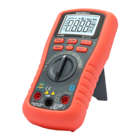
Maxwell 25301 User manual

User ManUal
BedienUngsanleitUng
Használati Utasítás
ManUal de Utilizare
Užívateľská prírUčka
DIGITAL MULTIMETER
DIGITALMULTIMETER
DIGITÁLIS MULTIMÉTER
MULTIMETRU DIGITAL
DIGITÁLNY MULTIMETER
Product code / Produktcode/ Termékkód / Cod produs / Kód produkta:
25301
EN
DE
HU
RO
SK
i
VC9802A+
www.netker8.hu

EN User Manual
safety warnings
• Follow the safety and usage instructions to
ensure proper operation and good condition
of the device.
• Proper operation is only guaranteed if the
measuring wires are intact. Do not use the
device if the wires appear to be defective. In
case of their being damaged, replace them
immediately.
• Never ground yourself when measuring
electricity. Do not touch metal pipes or other
objects, parts which may be grounded. To
ensure proper insulation from the ground use
insulating dry clothes, rubber-sole shoes, oor
mats or other insulating material.
• Always disconnect the power source from a
circuit before modifying it (soldering parts,
etc.). Even weak currents may be dangerous.
• To protect yourself and the device never
exceed the maximum inward values.
general description
Display 3 ½ digit LCD
Polarity automatic negative
polarity display
Nullication automatic
Measuring method A/D converter
Overload signal only„1/-1”is
displayed
Low battery signal
battery symbol
( ) appears on the
screen
Safety standard
CE EMC/LVD. The
device complies to
the IEC1010 standard
Touch protection CAT II Double
insulation
Operating
environmental
temperature
(relative humidity)
0-40 °C (< 80%)
Storage
temperature
(relative humidity)
-20 C - +60 °C (< 80%)
Battery 1 x 9V IEC 6F22 type
battery
Dimensions 189 mm x 92,5 mm
x35 mm
Weight 375g (with battery)
Accessories
user manual,
measuring wires (red
and black, 1 pair)
shock resistant case
electric cHaracteristics
Accuracy at +/- (% of displayed value + number
of digits) at 23 +/-5 °C, <75% relative humidity.
DC voltage
Range Accuracy Resolution
200 mV
+/- (0,5% + 3)
0,1 mV
2 V 1 mV
20 V 10 mV
200 V 100 mV
1000 V +/- (1,0% + 5) 1 V
Impedance 10MΩ
Overload protection 1000 VDC
AC voltage
Range Accuracy Resolution
2 V
+/- (0.8% + 5)
1 mV
20 V 10 mV
200 V 100 mV
750 V +/- (1.2% + 5) 1 V
Impedance 10MΩ
Overload protection 1000 VDC
Frequency range 200V: 40-400 Hz
750V: 40-200Hz
www.netker8.hu

User Manual EN
Resistance
Range Accuracy Resolution
200 +/- (0,8% + 5) 0,1
2 k
+/- (0,8% + 3)
1
20 k 10
200 k 100
2 M 1 k
200 M
+/-
(5,0%(rdg-
10)+ 20)
100 k
Overload protection 250V DC/AC RMS
DC current
Range Accuracy Resolution
200 mA +/- (0,8% + 3) 100 A
20 A +/- (1,2% + 4) 10 mA
20 mA +/- (2,0% + 5) 10 A
Maximal inward
current
20 A (for maximum
10 seconds)
Overload protection 0,2A / 250 V„F”fuse
20 A range not protected!
AC current
Range Accuracy Resolution
20 mA +/- (1,0% + 5) 10 A
200 mA +/- (3,0% + 10) 100 A
20 A +/- (2,0% + 5) 10 mA
Maximal inward
current
20 A (maximum 10
másodpercig)
Overload protection 0,2A / 250 V„F”
jelzésű biztosíték
20 A range not protected!
Frequency range 40-200 Hz
Capacity
Range Accuracy Resolution
20 nF
+/- (2,5% +
20)
10 pF
200 nF 100 pF
2 F 1 nF
200 F 100 nF
Overload protection 36V AC/DC RMS
Dióda teszt
Function Description Test state
Diode's opening
voltage
measured
Opening DC
current appr.
1 mA
closing DC
voltage appr.
3 V
Beeping sound
indicates if
the resistance
between the V/
Ohm and COM
connectors is
below 90
Opening
voltage appr.
3 V
Overload protection 250 V DC / AC RMS
WARNING: Do not connect external power to
the connectors!
Transistor hFE test
Function Description Test state
hFE
Measures the
amplication
factor of the
transistor (0-
1000)
(all types)
Base current
appr. 10 A
VCE kb. 3 V
Contact phase detector function
• Set the function switch to TEST position.
• Connect the red wire into the V connector.
• Touch the wire to the measured point, BUT
MAKE SURE THAT YOUR FINGERS ARE BEHIND
THE FINGER PROTECTION AREA AT ALL TIMES!
If there is a phase present, the device will beep
continuously, the light below the HOLD button lights up.,
and the display shows ’1’ . If there is no phase, the display
www.netker8.hu

EN User Manual
shows ’000’.
IMPORTANT!
• Make sure when measuring like above that the
function switch is always in TEST position!
TTL logical level measuring
• Set the function switch to TTL position.
• If the voltage is above 2,4V or the circuit is
open, the display will show an icon
• If the voltage is between 0,7V and 2,4V the
display will show an icon
• If the voltage is lower than 0,7V the display will
show an icon
Square signal function
• Connect the the black measuring wire to
the COM connector and the red one to the V
connector.
• Parameters of the outgoing signal: frequency
~50Hz, duty cycle ~50Hz, threshold: 4V
Usage
• Check the 9V battery and press the POWER
button. If the battery is depleted, the
symbol appears on the screen.
• Signs near the connectors warn about not
exceeding the shown values for inward current
or voltage to prevent damage to the inside
circuits.
• Set the function selection switch to the proper
position before measuring.
• If you are unsure about the range of the
measured value, switch to the highest
available one and go backwards from that
until you reach the proper range.
DC and AC voltage measuring
• Connect the black wire to the„COM”and the
red one to the„V/ ”connector.
• Set the function selection switch to the proper
V position and connect the wires to the power
source paralelly for the time of measurement.
Note:
• If you are unsure about the range of the measured value,
switch to the highest available one and go backwards
from that until you reach the proper range.
• If only„1”is displayed on the screen, it means overload.
Switch the range switch to a higher value.
• Do not connect voltage exceeding 1000V DC or 750V AC
to the connectors. Results may be displayed with higher
values but this may lead to damage in the inside circuits.
• Do not touch the high voltage circuits while measuring.
DC and AC current measuring
• Connect the black measuring wire to the
„COM”connector and the red one to the„mA”
connector (max. 200mA)
• Set the function switch to the proper range.
• Connect the wires paralelly to the power
source for the measurement.
• To measure current between 200mA and 20A
follow the above points but connect the red
wire to the„20A” connector.
Note:
• If you are unsure about the range of the measured value,
switch to the highest available one and go backwards
from that until you reach the proper range.
• If only„1”is displayed on the screen, it means overload.
Switch the range switch to a higher value.
• Maximum inward current may be 200mA or 20A based
on the connector used. (Time for test is maximum 10
seconds). A current too high may melt the fuse, which
needs to be replaced. The 20A range is not protected.
• Maximum charging voltage: 200mV.
Resistance measuring
• Connect the black wire to the„COM”connector
and the red one to the„V/ ”connector.
• Set the function switch to the desired
resistance range.
• Touch the wires to the measured circuit
paralelly.
WARNING!
• Make sure the measured circuit is not under
power!
• Maximum overload value for the connector is
250V (for max. 10 seconds).
Note:
• If the value of the measured resistor exceeds the
maximum value of the range and the device shows
overload („1”), select a higher range. With resistors
above 1M it may take a few seconds until the device
stabilizes the value. This is completely normal.
• If you do not connect a resistor to the connectors,„1”
will appear on the screen because of the range exceed.
• If measuring a resistor within a circuit, make sure the
circuit is not under power for the time of the test and
that all capacitors are discharged.
• Do not connect inward voltage to the device as that may
lead to damage to the inside circuits.
• Outward voltage in connectors is appr. 3V
Capacity measuring
• Set the function switch to F position.
• Connect the capacitor to the Cx connector, pay
www.netker8.hu

User Manual EN
attention to the correct polarity when needed.
Note:
If the measured capacitor's value exceed the maximum
value of the range and the device shows overload („1”),
select a higher range.
Unit: 1 nF=10-3 F or 1000 pF
Do not connect external voltage or current to the
connector. Turn o power and discharge capacitors
before measuring. Discharge electrolyte capacitors before
measuring!
Diode and continuity test
• Connect the black measuring wire to the
„COM”connector and the red one to the„V/ ”
connector. (Note: the polarity of the red wire
is +)
• Set the function switch to position.
• Connect the wires to the ends of the diode.
The opening voltage of the diode is displayed
on the screen.
• Connect the wires to the two points of
the circuit. There is a beeping sound if the
resistance is below 90.
Note:
• If you do not connect a part to the connector (or there is
a break), the screen will show„1”.
• The diode receives 1mA of current under the test.
• The display shows the opening voltage of the diode
in mV and overload if you connected the diode with
reverse polarity.
Transistor hFE test
• Set the function switch to hFE position.
• Determine if the transistor is NPN or PNP
and place the part into the connector
corresponding to its type.
• The amplication factor of the transistor is
displayed on the screen.
I = 10 A, VBC = 2,8 V
warning
• When measuring voltage make sure that the
wires do not connect to a current measuring
connector and that the function switch is not
set to resistance or diode measuring mode.
Always make sure that the wire is connected to
the proper connector.
• Be careful when measuring voltage above 50V,
especially with high voltage equipment.
• Avoid connecting to "live" circuits.
• When measuring current, disconnect the
power from the circuit before connecting the
multimeter and do not measure above 20A.
• Before measuring resistance and diode make
sure the circuit is not under power.
• Always use the proper function and range for
the measurement. If you have doubts about
the range of the measurement, select the
highest available one and move backwards
from that.
• Make sure that the wires and the insulation are
intact.
• Be careful, do not exceed the thresholds given
in the manual.
• Only replace fuses to the same type and value.
• When replacing batteries or fuses disconnect
all external power sources and turn the
multimeter o.
Maintenance
Battery replacement (1 x 9V)
• Disconnect all external power sources from the
device. Turn the multimeter o and remove
the measuring wires.
• Unscrew the screws and remove the lower
cover.
• Remove the depleted battery and replace it to
one of the same type.
Fuse replacement
• Disconnect all external power sources from the
device. Turn the multimeter o and remove
the measuring wires from the connectors.
• Unscrew the screws and remove the lower
cover.
• Replace the melted fuse to one of the same
type and value (5x20 mm, 200 mA / 250 V„F”
type.)
www.netker8.hu

DE Anwendungsinformation
sicHerHeitsHinweise
• Folgen Sie die Sicherheitshinweise in der
Bedienungsanleitung, so kann der gute
Zustand und Betrieb gesichert werden.
• Der adäquate Betrieb kann nur im Fall
garantiert werden, wenn die Messleitungen
im makellosen Zustand sind. Benutzen Sie
das Messgerät nicht, wenn die Messleitungen
geschädigt scheinen. Die defekete
Messleitungen müssen sofort getauscht
werden.
• Während elektrionischen Messungen erden
Sie sich nicht! Berühren Sie keine Metallröhre
und andere Ausläufe, Bestandteile, die
wahrscheinlich geerdet sind. Um die beste
Isolierung zu sichern, tragen Sie trockene
Kleider und Schuhe mit Gummi-Fußsohle oder
stehen Sie auf Gummi-Fußmatte.
• Bevor dem Umbau des Stromkreises (z.B:
Löten der Bestandteile), soll er entstromt
werden. Sehr kleine Menge Strom kann auch
gefährlich sein!
• Der maximale Eingangswert darf wegen des
Schutzes Ihrer Unversehrtheit und des Geräts
nicht überschritten werden.
allgeMeine daten
Anzeiger 3 ½ digit LCD-
Anzeiger
Polarität
automatische
Anzeige der
negativen
Polarität
Nullabgleich automatikus
Messmethode A/D Konverter
Überlastungsanzeige
nur „1/-1”
Überschrift ist
sichrtbar
Niedrige Batterie-
spannung
das Batterie-
Symbol
erscheint auf dem
Anzeiger
Sicherheitshinweis
CE EMC/LVD. Das
Gerät entspricht
IEC1010
Berührungsschutz- II Doppel-
isolierung
Betriebsumstände
Temperatur
(relative Luftfeuchtig-
keit)
0-40 °C (< 80%)
Lagerumstände
Temperatur
(relative
Luftfeuchtigkeit)
-20 C - +60 °C (<
80%)
Batterie 1x 9V IEC 6F22
Batterie
Größe 189 mm x 92,5
mm x35 mm
Gewicht 375g (mit
Batterie)
Zubehör
Bedienungs-
anleitung,
Messleitung
(schwarz und
rot, 1 Paar)
schlagfestes
Besteck
elektroniscHe daten
Präzision +/- (% des gezeigten Wertes +
Anzahl der Digite 23 +/-5 °C, relative
Luftfeuchtigkeit kleiner als 75%
DC Spannung
Messbereich Präzision Auösung
200 mV
+/- (0,5% + 3)
0,1 mV
2 V 1 mV
20 V 10 mV
200 V 100 mV
1000 V +/- (1,0% + 5) 1 V
Impedanz 10MΩ
Überlastungsschutz 1000 VDC
AC Spannung
www.netker8.hu

Anwendungsinformation DE
Messbereich Präzision Auösung
2 V
+/- (0.8% + 5)
1 mV
20 V 10 mV
200 V 100 mV
750 V +/- (1.2% + 5) 1 V
Impedanz 10MΩ
Überlastungsschutz 1000 VDC
Frequenzbereich 200V: 40-400 Hz
750V: 40-200Hz
Widerstnad
Messbereich Präzision Auösung
200 +/- (0,8% + 5) 0,1
2 k
+/- (0,8% + 3)
1
20 k 10
200 k 100
2 M 1 k
200 M
+/-
(5,0%(rdg-
10)+ 20)
100 k
Überlastungsschutz 250V DC/AC RMS
DC Strom
Messbereich Präzision Auslösung
200 mA +/- (0,8% + 3) 100 A
20 A +/- (1,2% + 4) 10 mA
20 mA +/- (2,0% + 5) 10 A
Max. Eingangsstrom 20 A (max. 10
Sekunden lang)
Überlastungsschutz
0,2A / 250 V
sicherung mit „F”
Zeichen
20 A Messbereich ist nicht gesichert!
AC Strom
Messbereich Präzision Auösung
20 mA +/- (1,0% + 5) 10 A
200 mA +/- (3,0% + 10) 100 A
20 A +/- (2,0% + 5) 10 mA
Max. Eingangsstorm 20 A (max. 10
Sekunden lang)
Überlastungsschutz
0,2A / 250 V
Sicherung mit„F”
Zeichen
20 A Messbereich ist nicht gesichert!
Frequenzbereich 40-200 Hz
Kapazität
Messbereich Präzision Auösung
20 nF
+/- (2,5% +
20)
10 pF
200 nF 100 pF
2 F 1 nF
200 F 100 nF
Überlastungsschutz 36V AC/DC RMS
Diodentest
Funktion Beschreibung Testzustand
Es wird
die Önungs-
spannung
der Diode
gemessen
DC Önungs-
strom ca. 1 mA
DC Schluss-
spannung ca.
3 V
Tonklang
meldet,wenn
der
Widerstand
zwischen V/
Ohm und COM
Anschlüsse
kleiner als 90
ist
Önungs-
spannung
ca. 3 V
Überlastungsschutz 250 V DC / AC RMS
Warnung: Schliessen Sie den Klemmen keine äußere
Spannnungsquelle an!
Transistor hFE Test
Funktion Beschreibung Test-
zustand
www.netker8.hu

DE Anwendungsinformation
hFE
Der
Strom-
verstärkungs-
faktor des
Transistors wird
gemessen (0-1000)
(alle Typen)
Basisstrom
kb. 10 A
VCE kb. 3 V
Kontakt-Fasensucher-Funktion
• Der Funktionsschalter soll in TEST Position
gestellt werden.
• Die rote Messleitungen sollen in die V
Eingangsbuchse verbindet werden.
• Berühren Sie mit der Prüfspitze den
messenden Gebiet! BEACHTEN SIE, DASS IHRE
FINGER WÄHREND DER MESSUNG IMMER
HINTER DEM FINGERSCHUTZ AM FÜHLERGRIFF
BLEIBEN!
• Falls eine Phase zu messen ist, meldet das
Gerät mit einem kontinuierlichen Tonklang,
die Lampe unter HOLD leuchtet rot und auf
dem Anzeiger erscheint '1'. Wenn es keine
Phase gibt, ist '000' auf dem Anzeiger zu
sehen.
Wichtig!
• Beachten Sie, dass der Funktionswahltschalter
bei Messungen IMMER in der Position TEST
stehen soll!
TTL logische Stufenmessungsfunktion
• Der Funktionswahlschalter soll in die Position
TTL gestellt werden.
• Falls die Spannung größer als 2,4 v ist oder der
Stromkreis nicht geshlossen ist, erscheint auf
dem Anzeiger das folgende Symbol
• Falls die Spannung zwischen 0,7 v und 2,4 V
liegt, erscheint auf dem Anzeiger
• Falls die Spannung kleiner als 0,7 V ist, ist das
Symbol auf dem Anzeiger zu sehen
Rechteckzeichen-Funktion
• Verbinden Sie die schwarze Messleitung in
die COM Buchse, die rote Messleitung in die V
Eingangsbuchse
• Parameters des Ausgnagssignals: Frequenz
~50Hz, ~50% Ausfüllungsfaktor, 4V Grenzwert
Anwendung
• Überprüfen Sie die 9V Batterie, dann drucken
Sie POWER
• Wenn die Batterie leer ist, erscheint auf dem
Anzeiger das Symbol
• Die Zeichen neben den Buchsen warnen
davor, dass der Eingangsstrom,- und
Spannung den gegebenen Wert nicht
überschreiten darf. So kann die Verletzung der
der inneren Stromkreise verhindert werden.
• Der Funktionswahlschalter soll bevor der
Messung in die adäquate Position (zur
gewählten Funktion) gestellt werden.
• Wenn Sie die Größe der messenden Menge
nicht kennen, stellen Sie den Schalter in den
höchsten Messbereich und bewegen Sie daher
rückwerts.
Messung von DC und AC Spannung
• Verbinden Sie den schwarzen Stecker in die
„COM”Buchse, den roten Stecker in die„V/ ”
Buchse.
• Stellen Sie den Funktionswahlschalter in die
messende V Position und verbinden Sie die
Taster in serieller Verbindung zur Stromquelle
zur Zeit der Messung.
Anmerkung:
• Wenn Sie die Größe der messenden Menge nicht
kennen, stellen Sie den Funktionswahlschalter in
den höchsten Messbereich und bewegen Sie daher
rückwerts solange Sie den angemessenes Wert erreichen
• "1" auf dem Anzeiger meldet Überlastung. Der
Funktionswahlschalter soll in einen höheren
Messbereich gestellt werden.
• Verbinden Sie keine Spannung, die größer als DC
1000 V / AC 750 V ist, in den Eingang. Die Anzeige ist
möglich auch an höherer Spannung, das kann aber zur
Verletzung der Stromkreise führen.
• Berühren Sie nicht die Stromkreise unter Hochspannung
während der Messung
Messung von DC und AC Strom
• Verbinden Sie das schwarze Kabel in die
„COM”Buchse, das rote Kabel in die „mA”
Buchse (max. 200 mA) oder in die„20A”
Buchse, zur Messung von 200 mA oder 20A
Strom.
• Stellen Sie den Funktionswahlschalter in den
adäquaten Messbereich.
• Zur Messung verbinden Sie die Taster eng zur
Stromquelle.
• Zur Messung von 200 mA und 20A, folgen Sie
die vorige Anleitung, nur die rote Messleitung
muss in die "20A" Buchse verbindet werden.
www.netker8.hu

Anwendungsinformation DE
Anmerkung:
• Wenn Sie die Größe der messenden Menge nicht
kennen, stellen Sie den Funktionswahlschalter in den
höchsten Messbereich und bewegen sie daher rückwerts
solange Sie den angemessenes Wert erreichen
• "1" auf dem Anzeiger meldet Überlastung. Der
Funktionswahlschalter soll in einen höheren
Messbereich gestellt werden.
• Der max. Eingangsstrom ist 200mA oder 20A
unabhängig von dem gewählten Eingang. (Der
Test dauert max. 10 Sekunden lang.) Die zu große
Stromstärke kann die Sicherung zerschmelzen, die so
getauscht werden muss. Der 20 A Messbereich ist nicht
gesichert. Max. Belastungsspannung: 200 mV.
Widerstandsmessung
• Verbinden Sie das schwarze Kabel in die„COM”
Buchse, das rote Kabel in die „V/ ”Buchse.
• Stellen Sie den Funktionswahlschalter in den
Messbereich des messenden Widerstands.
• Berühren Sie mit der Prüfspitze den
messenden Stromkreis parallel.
• Warnung: Sie sollen sichern, dass der
Stromkreis außer Spannung ist!
• Die max. Überlastung des Stromkreises: 250 V
RMS (max. 10 Sekunden lang).
Anmerkung:
• Falls das Wert des messenden Widerstands das max.
Wert des Messbereichs überschritt, das Gerät meldet
Überlastung ("1"), so sollen Sie einen größeren
Messbereich wählen. Über 1M Widerstand das Gerät
stabilisiert das gezeigtes Wert binnen einigen Minuten.
Das ist allgemein bei Messung größeres Widerstands.
• Falls Sie in den Eingang keinen Widerstand verbinden
(pl: Riß), der Anzeiger zeigt "1", dass es um Überlastung
des Messbereichs geht.
• Falls Sie den Widerstand in einem Stromkreis
untersuchen, soll es gesichert werden, dass
der Stromkreis außer Spannung steht und die
Kondensatoren ausgeladet sind.
• Die Verbindung des Eingangsstroms an das Gerät kann
zur Verletzung der inneren Stromkreise führen.
• An unbelsteten Klemmen liegt die Ausgangsspannung
um 3 V.
Kapazitätmessung
• Stellen Sie den Funktionswahlschalter in die F
Position.
• Verbinden Sie den Kondensator in die CX
Buchse, geachtet auf die richtige Polarität,
wenn es nötig ist.
Anmerkung:
Falls das Wert des messenden Kondensators das max.
Wert des Messbereichs überschritt und das Gerät meldet
Überlastung ("1"), Sie sollen einen größeren Messbereich
wählen.
Maßeinheit: 1 nF=10-3 F oder 1000 pF
Verbinden Sie keine äußere Spannung oder Strom in die
Buchse. Vor der Messung sollen Kondensatoren und die
Stromunterbrechung ausgeladet werden. Die Elektrolit-
Kondensatoren solllen vor der Messung ausgeladet
werden.
Dioden,- und Kontinuitätstest
• Verbinden Sie die schwarze Messleitung in die
„COM”Buchse, die rote Messleitung in die „V/
”Buchse. (Anmerkung: Polarität des roten
Tasters: +)
• Der Funktionswahlschalter soll in die
Position gestellt werden.
• Berühren Sie die Ausläufe der Diode mit
den Tastern. Auf dem Anzeiger ist die
Önungsspannung der Diode zu sehen.
• Berühren Sie zwei Punkte des Stromkreises
mit den Tastern. Tonsignal meldet, wenn der
Widerstand kleiner als 90 ist.
Anmerkung:
• Falls Sie in den Eingang keinen Bestandteil verbinden
(pl: Riß), auf dem Anzeiger ist "1" zu sehen.
• Während des Test läuft durch die Diode 1 mA.
• Auf dem Anzeiger ist die Önungsspannung der Diode
in mV und Überlastung (falls die Diode mit umgekehrter
Polarität verbindet ist) zu lesen.
Transistor hFE Test
• Der Funktionswahlschalter soll in die hFE
Position gestellt werden.
• Es soll festgestellt werden, ob der Transistor
NPN oder PNP ist und stellen Sie den
Bestandteil der Fussverteilung entsprechend
in die richtige Buchse.
• Auf dem Anzeiger ist der
Stromverstärkungsfaktor des Transistors zu
lesen
I = 10 A, VBC = 2,8 V
warnUng
• Bei Messung von Spannung soll es
gesichert weden, dass die Kabel nicht an
strommessenden Buchsen verbindet sind
und der Funktionswahlschalter darf nicht in
die Positionen Widerstand oder Diodentest
stehen. Sie sollen immer überprüfen, ob das
Kabel der messenden Menge entsprechend in
die richtige Buchse verbindet ist.
• Seien Sie vorsichtig bei Messung
größerer Werte als 50 V , vor allem bei
Starkstromgeräten.
• Vermeiden Sie die Verbindung an lebendigen
www.netker8.hu

DE Anwendungsinformation
Stromkreisen.
• Bei Strommessung soll der Stromkreis außer
Spannung stehen, bevor es abgebrochen
wird, um es zum Multimeter zu verbinden.Bei
Messungen schreiten sie 20 A nicht über!
• Zur Zeit von Widerstandsmessung und
Diodentest sollen Sie sichern, dass der
Stromkreis außer Spannung steht.
• Wählen Sie immer die adäquaten Funktion
und Messbereich bei Messungen! Falls die
größe der messenden Menge fraglich ist,
wählen Sie den größten Messbereich und
bewegen Sie daher rückwerts.
• Überzeugen Sie sich, ob die Messleitung
makellos und die Isolierung unverletzt ist.
• Seien Sie vorsichtig und überschreiten Sie
nicht die gegeben Überlastungswerte.
• Die Sicherungen dürfen nur für den gleichen
Typ und Wert ausgetauscht werden.
• Bevor der Önung des Bestecks bei Batterie,-
oder Sicherungsasutausch, sollen alle äußere
Stromkreise und auch der Multimeter
ausgeschaltet werden.
instandHalten
Batterieausrausch (1 db 9V-os)
• Die äußere Stromkreise sollen vom Messgerät
abgetrennt werden. Schalten Sie den
Multimeter aus und ziehen Sie die Messleitung
aus der Buchse aus!
• Drehen Sie die Schrauben aus und nehmen Sie
den unteren Deckel ab.
• Entfernen Sie die leere Batterie und tauschen
Sie für eine Neue aus dem gleichen Typ.
Sicherungsaustausch
• Die äußere Stromkreise sollen vom Messgerät
abgetrennt werden. Schalten Sie den
Multimeter aus und sehen Sie die Messleitung
aus der Buchse aus!
• Drehen Sie die Schrauben aus und nehmen Sie
den unteren Deckel ab.
• Tauschen Sie die geschmolzene Sicherung für
eine Neue aus dem gleichen Typ und Wert.
(5x20 mm, 200 mA / 250 V„F”.)
www.netker8.hu

Használati utasítás HU
Biztonsági
figyelMeztetések
• Kövesse a biztonsági és használati utasításokat,
így biztosíthatja a műszer biztonságos
működését és jó állapotát.
• A megfelelő működés csak a műszerzsinórok
hibátlan állapota mellett garantált. Ne
használja a műszert, ha a mérőzsinórok
sérültnek tűnnek. Sérülésük esetén azonnal
cserélje ki azokat.
• Soha ne földelje le magát, miközben
elektromos méréseket végez. Ne érjen kiálló
fém csövekhez,más egyéb kivezetésekhez,
alkatrészekhez,melyek esetleg földelve
vannak. A földtől való minél jobb szigetelés
érdekében használjon jól szigetelő száraz
ruhát, gumitalpú cipőt, lábtörlőt vagy egyéb
szigetelőanyagot.
• Mindig áramtalanítsa az áramkört mielőtt
átalakítja azt(alkatrészek forrasztása stb.). A kis
erősségű áram is lehet veszélyes.
• A készülék és személyes védelme érdekében
soha ne lépje túl a maximális bemenő
értékeket.
általános leírás
Kijelző 3 ½ digites LCD
Polaritás automatikus negatív
polaritás kijelzés
Nullázás automatikus
Mérési eljárás A/D konverter
Túlterhelés kijelzés csak az„1/-1” felirat
látható
Alacsony
telepfeszültség
az elem( )
szimbólum
megjelenik a kijelzőn
Biztonsági előírás
CE EMC/LVD. A
műszer megfelel az
IEC1010 szabványnak
Érintésvédelmi
osztály II Kettős szigetelésű
Üzemi környezeti
hőmérséklet
(relatív
páratartalom)
0-40 °C (< 80%)
Tárolási környezeti
hőmérséklet (relatív
páratartalom)
-20 C - +60 °C (< 80%)
Elem 1 db 9V-os IEC 6F22
típusú elem
Méretek 189 mm x 92,5 mm
x35 mm
Tömeg 375g (elemmel)
Tartozékok
használati utasítás,
műszerzsinór (piros
és fekete,1 pár),
ütésvédő tok
elektroMos jelleMzők
A pontosság +/- (kijelzett érték %-a + digitek
száma) 23 +/-5 °C-on, 75%-nál kisebb relatív
páratartalom esetén
DC feszültség
Méréshatár Pontosság Felbontás
200 mV
+/- (0,5% + 3)
0,1 mV
2 V 1 mV
20 V 10 mV
200 V 100 mV
1000 V +/- (1,0% + 5) 1 V
Impedancia 10MΩ
Túlterhelés elleni
védelem 1000 VDC
AC feszültség
Méréshatár Pontosság Felbontás
2 V
+/- (0.8% + 5)
1 mV
20 V 10 mV
200 V 100 mV
750 V +/- (1.2% + 5) 1 V
www.netker8.hu

HU Használati utasítás
Impedancia 10MΩ
Túlterhelés elleni
védelem 1000 VDC
Frekvencia tartomány 200V: 40-400 Hz
750V: 40-200Hz
Ellenállás
Méréshatár Pontosság Felbontás
200 +/- (0,8% + 5) 0,1
2 k
+/- (0,8% + 3)
1
20 k 10
200 k 100
2 M 1 k
200 M
+/-
(5,0%(rdg-
10)+ 20)
100 k
Túlterhelés elleni
védelem 250V DC/AC RMS
DC áram
Méréshatár Pontosság Felbontás
200 mA +/- (0,8% + 3) 100 A
20 A +/- (1,2% + 4) 10 mA
20 mA +/- (2,0% + 5) 10 A
Maximális bemenő
áram
20 A (maximum 10
másodpercig)
Túlterhelés elleni
védelem
0,2A / 250 V„F”
jelzésű biztosíték
20 A-es méréshatár nincs biztosítva!
AC áram
Méréshatár Pontosság Felbontás
20 mA +/- (1,0% + 5) 10 A
200 mA +/- (3,0% + 10) 100 A
20 A +/- (2,0% + 5) 10 mA
Maximális bemenő
áram
20 A (maximum 10
másodpercig)
Túlterhelés elleni
védelem
0,2A / 250 V„F”
jelzésű biztosíték
20 A-es méréshatár nincs biztosítva!
Frekvencia tartomány 40-200 Hz
Kapacitás
Méréshatár Pontosság Felbontás
20 nF
+/- (2,5% +
20)
10 pF
200 nF 100 pF
2 F 1 nF
200 F 100 nF
Túlterhelés elleni
védelem 36V AC/DC RMS
Dióda teszt
Funkció Leírás Teszt állapot
A dióda
nyitófeszültségét
méri
Nyitóirányú DC
áram kb. 1 mA
Záró irányú DC
feszültség kb.
3 V
Sípoló hang jelzi,
ha a V/Ohm és a
COM csatlakozók
közötti ellenállás
kisebb, mint
90
Nyitófeszültség
kb. 3 V
Túlterhelés elleni
védelem 250 V DC / AC RMS
Figyelmeztetés: Ne csatlakoztasson a
kapcsokra külső feszültségforrást!
Tranzisztor hFE teszt
Funkció Leírás Teszt állapot
hFE
A tranzisztor
áramerősítési
tényezőjét méri
(0-1000)
(Minden típus)
Bázisáram kb.
10 A
VCE kb. 3 V
www.netker8.hu

Használati utasítás HU
Kontaktos fáziskereső funkció
• Állítsa a funkciókapcsolót TEST állásba.
• Csatlakoztassa a V bemeneti aljzatba a piros
mérővezetéket.
• Érintse a mérőcsúcsot a mérendő ponthoz, DE
ÜGYELJEN ARRA, HOGY AZ UJJAI MINDIG A
MÉRŐNYÉL UJJVÉDŐI MÖGÖTT MARADJANAK!
Ha van jelen fázis, akkor a műszer folyamatos sípoló
hangot ad és a HOLD gomb alatti lámpa pirosan ég, illetve
a kijelzőn ’1’ felirat lesz, ha pedig nincs fázis, akkor ’000’
kijelzés tapasztalható.
FONTOS!
• Ügyeljen rá, hogy ezen méréskor MINDIG a
TEST állásban legyen a funkciókapcsoló!
TTL logikai szint mérés funkció
• Állítsa a funkciókapcsolót TTL állásba.
• Ha a feszültség nagyobb, mint 2,4V vagy
nyitott az áramkör, akkor a kijelzőn ikon
jelenik meg
• Ha a feszültség 0,7V és 2,4V között van, akkor a
kijelzőn ikon jelenik meg
• Ha a testfeszültség kisebb, mint 0,7V, akkor a
kijelzőn ikon jelenik meg
Négyszögjel funkció
• Csatlakoztassa a COM bemeneti aljzatba
a fekete és a V bemeneti aljzatba a piros
mérővezetéket.
• A kimeneti jel paraméterei: ~50Hz-es freq.,
~50%-os kitöltési tényező, 4V-os határérték
Használat
• Ellenőrizze a 9 V-os elemet, majd nyomja be a
POWER gombot. Ha az elem lemerült, az
szimbólum megjelenik a kijelzőn.
• Az aljzatok melletti jelzések gyelmeztetnek,
hogy a bemenő feszültség vagy áram
ne haladja meg a jelzett értéket. Így
megakadályozhatja a belső áramkörök
sérülését.
• A funkcióválasztó kapcsolót a mérés előtt
állítsa a megfelelő állásba (funkcióhoz)
• Ha a mérendő mennyiség nagyságrendjét
nem ismeri, állítsa a kapcsolót a legmagasabb
méréshatárra és onnan haladjon visszafelé,
amíg a megfelelő értéket eléri.
DC és AC feszültség mérése
• Csatlakoztassa a fekete csatlakozót a„COM”, a
piros csatlakozót a„V/ ”aljzatba.
• Állítsa a funkcióválasztó kapcsolót a megfelelő
V pozícióba és csatlakoztassa a tapogatókat
párhuzamosan a feszültségforrással a mérés
idejére.
Megjegyzés:
• Ha a mérendő mennyiség nagyságrendjét nem ismeri,
állítsa a kapcsolót a legmagasabb méréshatárra és
onnan haladjon visszafelé, amíg a megfelelő értéket
eléri.
• Ha csak az„1” látható a kijelzőn, az a túlterhelést jelzi.
Ilyenkor kapcsolja a funkciókapcsolót magasabb
méréshatárba.
• Ne kapcsoljon DC 1000 V / AC 750 V-nál magasabb
feszültséget a bemenetre. A kijelzés lehetséges
magasabb feszültségeken is, de ez a belső áramkörök
sérüléséhez vezethet.
• Ne érintse a nagyfeszültségű áramköröket mérés
közben.
DC és AC áram mérése
• Csatlakoztassa a fekete vezetéket a„COM”, a
piros vezetéket pedig a„mA”(max. 200 mA)
vagy„20A” jelzésű aljzatba, 200 mA-es illetve
20A-es méréshez.
• Állítsa a funkció kapcsolót a megfelelő
méréshatárhoz.
• Csatlakoztassa a tapogatókat sorosan az
áramforrással a méréshez.
• 200 mA és 20 A közötti áram méréséhez az
előző pontokat kövesse, de a piros mérőzsinórt
a„20A”jelzésű aljzatba csatlakoztassa.
Megjegyzés:
• Ha a mérendő áram nagyságrendjét nem ismeri, állítsa
a kapcsolót a legmagasabb méréshatárra és onnan
haladjon visszafelé, amíg a megfelelő értéket eléri.
• Ha csak az„1” látható a kijelzőn, az a túlterhelést jelzi.
Ilyenkor kapcsolja a funkciókapcsolót magasabb
méréshatárba.
• A maximális bemenő áram 200 mA vagy 20 A a
választott bemenettől függően. (A teszt ideje max. 10
másodperc.) A túl nagy áramerősség a biztosítékot
kiolvasztja, amit ki kell cserélni. A 20 A-es méréshatár
nincs biztosítva.
• Maximális terhelőfeszültség: 200 mV.
Ellenállásmérés
• Csatlakoztassa a fekete vezetéket a„COM”, a
piros vezetéket pedig a„V/ ”aljzatba.
• Állítsa a funkciókapcsolót a kívánt ellenállás
méréshatárra.
• Érintse a mérőhegyeket a mérendő
áramkörhöz, de azzal párhuzamosan.
Figyelmeztetés: biztosítsa a mérendő áramkör
www.netker8.hu

HU Használati utasítás
feszültségmentességét!
• A bemenet maximális túlterhelhetősége: 250 V
RMS (max. 10 másodpercig).
Megjegyzés:
• Ha a mérendő ellenállás értéke meghaladja a
méréshatár maximális értékét, és a műszer túlterhelést
jelez („1”), válasszon egy magasabb méréshatárt. 1M
fölötti ellenállásoknál a műszer néhány másodperc alatt
stabilizálja a kijelzett értéket. Ez teljesen normális nagy
értékű ellenállások mérésénél.
• Ha a bemenetre nem csatlakoztat ellenállást (pl.
szakadás), a kijelzőn az„1” felirat jelenik meg a
méréshatár túllépés miatt.
• Ha áramkörben lévő ellenállást vizsgál, biztosítsa, hogy
a teszt alatt az áramkör feszültségmentes legyen, és a
kondenzátorok legyenek kisütve.
• Ne kapcsoljon a műszerre bemenő feszültséget, mert az
a belső áramkörök sérüléséhez vezethet.
• Terheletlen kapcsokon a kimeneti feszültség kb. 3 V.
Kapacitásmérés
• Állítsa a funkcióválasztó kapcsolót F állásba.
• Csatlakoztassa a kondenzátort a CX jelű
aljzatba, ügyelve a helyes polaritásra, amikor
szükséges.
Megjegyzés:
Ha a mérendő kondenzátor értéke meghaladja a
méréshatár maximális értékét, és a műszer túlterhelést
jelez („1”), válasszon egy magasabb méréshatárt.
Mértékegység: 1 nF=10-3 F vagy 1000 pF
Ne csatlakoztasson külső feszültséget vagy áramot az
aljzatba. Mérés előtt kapcsolja ki a tápfeszültséget és a
kondenzátorokat süsse ki. Az elektrolit kondenzátorokat
mérés előtt süsse ki!
Dióda és folytonosság teszt
• Csatlakoztassa a fekete műszerzsinórt a„COM”,
a pirosat a„V/ ”aljzatba. (Megjegyzés: a piros
tapogató polaritása: +)
• Állítsa a funkció kapcsolót a állásba.
• Érintse a tapogatókat a dióda kivezetéseihez. A
kijelzőn a dióda nyitófeszültsége látható.
• Érintse a tapogatókat az áramkör két pontjára.
Sípoló hang jelez, ha az ellenállás kisebb 90
-nál.
Megjegyzés:
• Ha a bemenetre nem csatlakoztat alkatrészt (pl.
szakadás), a kijelzőn az„1” felirat jelenik meg.
• A diódán 1 mA áram folyik a teszt alatt.
• A kijelzőn a dióda nyitófeszültsége olvasható mV-
ban, és túlterhelés, ha a diódát fordított polaritással
csatlakoztatta.
Tranzisztor hFE teszt
• Állítsa a funkciókapcsolót a hFE állásba
• Határozza meg, hogy a tranzisztor NPN vagy
PNP, és helyezze az alkatrészt a lábkiosztásának
megfelelő csatlakozóba.
• A kijelzőről a tranzisztor áramerősítési
tényezője olvasható le.
I = 10 A, VBC = 2,8 V
figyelMeztetés
• Feszültség mérésénél biztosítsa, hogy a
vezetékek ne csatlakozzanak árammérő
aljzathoz és a funkciókapcsoló ne legyen
ellenállás vagy dióda ellenőrző állásban.
Mindig ellenőrizze, hogy a mérendő
mennyiségnek megfelelő aljzatba
csatlakoztatta-e a vezetéket.
• Legyen körültekintő 50 V-nál nagyobb
feszültség mérésekor, különösen erősáramú
berendezéseknél.
• Kerülje az„élő” áramkörökhöz való
csatlakozást.
• Árammérésnél az áramkört
feszültségmentesítse, mielőtt megszakítaná,
hogy csatlakoztassa hozzá a multimétert, és ne
mérjen 20 A-nél nagyobb áramot.
• Ellenállásmérés és dióda tesztelés
előtt gondoskodjon az áramkör
feszültségmentesítéséről a mérés idejére.
• Mindig a mérésnek megfelelő funkciót és
méréshatárt válassza. Ha kétséges a mérendő
mennyiség nagyságrendje, válassza a
legmagasabb méréshatárt és onnan haladjon
visszafelé.
• Győződjön meg a műszerzsinór hibátlan
állapotáról, a szigetelés sértetlenségéről.
• Legyen óvatos, ne lépje túl a leírásban
megadott túlterheléshatárokat.
• Biztosítékot csak azonos típusúra és értékűre
cseréljen.
• Biztosíték- vagy elemcserénél a műszer
tokjának kinyitása előtt kapcsoljon le minden
külső áramkört és kapcsolja ki a multimétert.
karBantartás
Elemcsere (1 db 9V-os)
• Kapcsoljon le minden külső áramkört a
műszerről. Kapcsolja ki a multimétert és a
műszerzsinórt húzza ki az aljzatból.
www.netker8.hu

Használati utasítás HU
• Csavarja ki a csavarokat és emelje le az alsó
fedelet.
• Távolítsa el a lemerült elemet és cserélje ki
ugyanolyan típusúra.
Biztosítékcsere
• Kapcsoljon le minden külső áramkört a
műszerről. Kapcsolja ki a multimétert és a
műszerzsinórt húzza ki az aljzatból.
• Csavarja ki a csavart és emelje le az alsó
fedelet.
• Cserélje ki a kiolvadt biztosítékot ugyanolyan
típusúra és értékűre. (5x20 mm, 200 mA / 250
V„F”jelzésű.)
www.netker8.hu

RO Manual de utilizare
avertizĂri de
sigUranŢÂ
• Urmaţi toate instrucţiunile de siguranţă şi de
funcţionare pentru a garanta funcţionarea în
siguranţă a instrumentului în stare bună.
• Funcţionarea corectă este posibilă doar dacă
starea cablurilor de măsurare este impecabilă.
Nu utilizaţi aparatul daca cablurile sunt
deteriorate. Schimbaţi cablurile dacă sau
deteriorat.
• Să nu vă împământaţi când faceţi măsurări
electrice. Nu atingeţi ţevi metalice, alte
prize, piese electrice care sunt împământate.
Motiv pentru o mai bună izolare, utilizaţi o
îmbrăcăminte bun izolator uscat, panto
cu talpi de cauciuc, mat sau alte materiale
izolante.
• Scoateţi circuitul de sub current electric înainte
de modicare (lipirea pieselor electronice,
etc). Curentul de mică intensitate poate
periculoasă.
• Pentru siguranţa dvs şi al aparatului nu
depăşiţi valorile maxime de intrare.
prezentere generalĂ
Aşaj LCD cu 3 ½ digite
Polaritate Aşare automată a
polarităţii negative
Reducere la 0 automat
Metoda de
măsurare Convertor A/D
Depăşire domeniu Simbol“1” / “-1”
Baterie epuizată Simbolul baterie ()
apare pe aşaj
Electrosecuritate Corespunde
normelor CEEMC
Clasa de izolaţie LVDA şi IEC 1010
Temperature de
lucru Clasa II, izolţie dublă
Umiditate relativă 0…40 °C
Temperatura de
stocare < 80%
Umiditate relativă -20 C…+60 °C
Baterie < 80%
Dimensiuni 1 buc de 9V tip 6F22
IEC
Greutate 189 mm x 92,5 mm
x35 mm
Accesorii 375g (cu baterie)
manual de utlizare,
cabluri de măsurare,
toc de protecţie
caracteristici
electrice
Precizia +/- (% a valorii măsurate + nr. digitelor)
la 23° ±5 °C la UR mai micã de 75%.
Tensiune DC
Domeniu precizia rezoluţia
200 mV
+/- (0,5% + 3)
0,1 mV
2 V 1 mV
20 V 10 mV
200 V 100 mV
1000 V +/- (1,0% + 5) 1 V
Impedanţa: 10 M 10MΩ
Protecţia la
suprasarcină: 1000
VDC
1000 VDC
Tensiune AC
Domeniu Percizia rezoluţia
2 V
+/- (0.8% + 5)
1 mV
20 V 10 mV
200 V 100 mV
750 V +/- (1.2% + 5) 1 V
www.netker8.hu

Manual de utilizare RO
Impedanţa 10MΩ
Protecţia la
suprasarcină 1000 VDC
Domeniu frecvenţe 200V: 40-400 Hz
750V: 40-200Hz
Rezistenţa
Domeniu Percizia rezoluţia
200 +/- (0,8% + 5) 0,1
2 k
+/- (0,8% + 3)
1
20 k 10
200 k 100
2 M 1 k
200 M
+/-
(5,0%(rdg-
10)+ 20)
100 k
Protecţie la
suprasarcină 250V DC/AC RMS
Curent DC
Domeniu Percizia rezoluţia
200 mA +/- (0,8% + 3) 100 A
20 A +/- (1,2% + 4) 10 mA
20 mA +/- (2,0% + 5) 10 A
Curent max. de
intrare 20 A (max. pt. 10 sec.)
Protecţie la
suprasarcină
0,2A / 250 V fuzibil
marcat“F”
domeniul 20A neprotejat
Curent AC
Domeniu Percizia rezoluţia
20 mA +/- (1,0% + 5) 10 A
200 mA +/- (3,0% + 10) 100 A
20 A +/- (2,0% + 5) 10 mA
Curent max. de
intrare 20 A (max. pt. 10 sec.)
Protecţie la
suprasarcină
0,2A / 250 V fuzibil
marcat“F”
domeniul 20A neprotejat
Domeniu frecvenţe 40-200 Hz
Capacitate
Domeniu Percizia rezoluţia
20 nF
+/- (2,5% +
20)
10 pF
200 nF 100 pF
2 F 1 nF
200 F 100 nF
Protecţia la
suprasarcină 36V AC/DC RMS
Test diode
Funcţie Descriere Stare test
Măsoara
tensiunea de
deschidere a
diodei
curent DC de
deschidere 1
mA.
Tensiune DC
de închidere
aprox. 3 V
Semnalizare
sonoră dacă între
V/Ohm şi COM
rezistenţa este
mai mică decăt
90
Tensuiune de
deschidere 3 V.
Pretecţie la
suprasarcină 250 V DC / AC RMS
Atenţie:nu conectaţis surse externe de curent
electric la conectori
Test transistor hFE
Funcţia Descriere Stare test
hFE
Măsoară
factorul de
amplicare în
curent (0-1000)
(toate tipurile)
Curent de
bază aprox.
10 A
VCE aprox. 3 V
www.netker8.hu

RO Manual de utilizare
KCăutarea fazei prin contact
• Reglaţi selectorul de funcþii în poziţia TEST
• Conectaþi cablul de mãsurare roşu în mufa V
• Atingeţi punctul de testare, În timp aveţi grijă
să ţineţi degetele tot timpul pe partea izolată
a testerului.
Dacã faza este prezentã, vom auzi un semnal acustic,
lumina roşie de sub
tasta HOLD va lumina şi pe aşaj va apare cifra “1”.
În lipsa fazei, pe aşaj va apare“000”.
IMPORTANT!
• La aceastã mãsurare, selectorul va mereu în
poz. TEST
Mãsurarea nivelului logic TTL
• Reglaţi selectorul de funcţii în poz. TTL.
• Dacă tensiunea este mai mare de 2.4V
ikon jelenik megatunci simbolul va apare pe
ecran
• Dacă tensiunea este între 0.7V – 2.4V atunci
simbolul apare pe ecran
• Dacă tensiunea este mai mică decăt 0.7V
atunci simbolul va apare pe ecran
Funcţia semnal rectangular
• Conectaţi cablul negru la mufa COM şi cel roţu
la mufa V
• Semnalul de ieţire va de 50 Hz, factor de
umplere cca. 50%, U=4V
Utilizare
• Vericaţi bacteria de 9V şi apăsaţi butonul
POWER.Dacă bacteria este descărcată simbulul
va apare pe ecran.
• Lângã mufe se aã inscripþionate valorile
limitã de intrare. Respectând
• aceste valori veţi proteja circuitele interne al
aparatului.
• Reglaţi selectorul de funcþii în poziia
necesarã.
• Dacã nu cunoaşteţi valoarea de mãsurat,
începeţi mãsurarea pe un
• domeniu superior - scãzând treptat pânã la
valoarea corectã.
Măsurarea tensiunii AC/ DC
• Conectaţi cablul negru în mufa COM şi cel roşu
în mufa V/
• Mutaţi selectorul în poziţia V necesară şi
conectaţi cablurile de măsurare în parallel cu
sursa de tensiune pt. măsurare.
Notă:
• Dacã nu cunoaşteþi valoarea de mãsurat, începeţi
mãsurarea pe un
• domeniu superior - scãzând treptat pânã la valoarea
corectã.
• Simbolul 1 sau -1 denotã depãşirea domeniului reglat.
În acest caz,
• mutaţi selectorul pe un domeniu superior.
• Nu conectaţi tensiuni mai mari decăt 1000V DC/ 750V AC
la intrare. Aşarea valorilor este posibilă şi la tensiuni
mai mari dar aceasta duce la defectarea circuitelor
interne.
• Nu atingeţi circuitele de înaltă tensiune în timpul
măsurării.
Măsurarea curentului AC/DC
• Conectaţi cablul de mãsurare negru în mufa
COM şi cablul roşu în
• mufa 200mA respectiv 10A - funcţie de
curentul maxim mãsurat.
• Reglaţi selectorul de funcţii în poz.
Corespunzãtoare
• Conectaţi cablurile de măsurare în serie cu
sursa de curent.
• Pentru măsurarea curentului într 200mA şi 10A
urmaţi instrucţiunile de mai sus, dar cablul
roşu să e conectat la mufa“10A”.
Notă:
• Dacã nu cunoaşteþi valoarea de mãsurat, începeþi
mãsurarea pe un
• domeniu superior - scãzând treptat pânã la valoarea
corectã.
• Simbolul 1 sau -1 denotã depãşirea domeniului reglat.
În acest caz,
• mutaţi selectorul pe un domeniu superior.
• Curentul max. de intrare este 200mA sau 10A depinde
de intrarea selectată. (timpul de măsurare 10 secunde.).
Curenturi de prea mare intensitate poate topi siguranţa
fuzibilă care trebuie schimbată. Domeniul 20A
neprotejat.
• Sarcina maximă: 200mV.
Măsurarea rezistenţei
• Conectaţi cablul negru în mufa COM şi cel roşu
în mufa V/
• Mutaţi selectorul în poziţia necesară
• Conectaţi cablurile de măsurare în parallel cu
circuitul de măsurat. Atenţie, asiguraţi-vă că
circuitul nu este sub current electric.
• Protecţia la suprasarcinã: 250V RMS (max 10
sec.)
www.netker8.hu

Manual de utilizare RO
Notă:
• Dacã valoarea rezistenþei depãşeşte valoarea maximã a
domeniului ales,
• va apare cifra 1 sau -1 pe aşaj. Selectaţi un domeniu
superior.
• La valori peste 1 Mohm aparatul necesitã un scurt
interval de timp
• pentru stabilizarea valorii aşate. Acest fenomen este
normal la măsurarea rezistenţelor mari.
• Dacă nu conectaţi rezistenţă la intrare (ex. Rupere)
atunci pe aşaj apare“1” pentru depăşirea domeniului
de măsurare.
• Dacă măsuraţi rezistenţa într-un circuit asiguraţi-vă că
nu se aă sub tensiune şi toate condensatoarele sunt
descărcate. (conectaţi pricioarele condensatorii pt 10-
20s şi măsuraţi cu V dacă sa reuşit descărcare.)
• Nu conectaţi surse de tensiune la intrare oentru că poate
duce la defectarea circuitelor interne al aparatului.
• Tensiunea de ieşire aprox. 3V.
Măsurarea capacităţii
• Reglaþi selectorul de funcii în poz. F
• Conectaţi condensatorul la conectorul marcat
CX, avănd grijă la polaritate cand este necesar.
Notă:
Dacă valoarea condensatorului depăşeşte valoarea
maximă a domeniului de măsurat pe aşaj apara“1”,
selectaţi un domeniu superior.
Unitatea de măsură: 1 nF=10-3 F sau 1000 pF
Nu conectaţi sursă exterioară de tensiune sau de current
la mufă. Opriţi sursa de current electric şi decărcaţi
condensatoarele.descărcaţi condensatoarle electroliţi
înainte de măsurare (conectaţi pricioarele condensatorii
pt 10-20s şi măsuraţi cu V dacă sa reuşit descărcare.)
Test diodã şi continuitate
• Conectaţi cablul negru în mufa COM şi cel roşu
în mufa V/ (notă: terminalul roşu este +)
• Reglaţi selectorul de funcţii în poz.:
• Atingeţi terminalele diodei. În sens direct,
pe aşaj va apare tensiunea dedeschidere a
diodei.
• Atingeţi terminalele circuitului de testat. Dacã
rezistenţa circuitului e mai micã de 90 ohmi, va
apare un semnal sonor.
Notă:
• Dacă nu conectaţi piesa la intrare (ex. Rupere) pe aşaj
apare“1”.
• În timpul testării prin diodă va trece current de 1 mA.
• Pe aşaj se poate citi valoarea tensiunii de deschidere
a diodei în mV, şi suprasarcină dacă polariatea este
greşită.
Test tranzistoare hFE
• Reglaþi selectorul de funcþii în poz. hFE
• Întroduceþi tranzistorul în soclu þinând cont
de felul acestuia (NPN sau PNP).
• Pe alaj va apare factorul de amplicare în
curent al tranzistorului.
• I =10A, V =2,8 VBC
atenŢie
• Asiguraţi-vă la măsurarea tensiunii să nu
e cabluri conectate la mufa de măsurare a
curentului şi comutatorul să nu e la poziţia
rezistenţei su la test diode. Vericaţi ca
cablurile au fost conectate la mufa cu vloarea
corectă.
• Atenţie la mãsurarea tensiunilor mai mari de
50 V, mai ales la aparate cu intensitate mare.
• Evitaţi conectarea la circuite “vii”.
• La mãsurarea curenţilor decuplaţi alimentarea
circuitului înainte de mãsurari şi nu mãsuraţi
curenţi peste 20A.
• Deconectaţi alimentarea circuitelor în modul
rezistenţã sau test diodã
• Selectaţi cu atenţie modul de lucru. Dacã
nu cunoaşteţi valoarea de mãsurat, începeţi
mãsurarea pe un domeniu superior - scãzând
treptat pânã la valoarea corectã.
• Folosiţi numai cabluri de mãsurare în stare
perfectã.
• Nu depãşiţi valorile maxime înscrise lângã
mufe
• Schimbaţi siguranţa numai cu unul de tip şi
valoare identicã.
• La schimbarea siguranţei sau a bateriei
decuplaţi cablurile de mãsurare
• de la aparat şi opriţi aparatul.
ÎntreŢinere
Schimb de baterii (I buc. de 9V)
• Deconectaţi ciercuitele externe de aparat.
Opriţi multimetrul şi deonectaţi cablurile de
măsurare din mufe.
• Deşurubaţi şuruburile şi ridicaţi capacul din
spate.
• Scoateţi bacteria descărcată şi schimbaşi
baterie cu unul de fel.
www.netker8.hu

RO Manual de utilizare
Schimbarea siguranţei
• Deconectaţi ciercuitele externe de aparat.
Opriţi multimetrul şi deonectaţi cablurile de
măsurare din mufe.
• Deşurubaţi şuruburile şi ridicaţi capacul din
spate.
• Schimbaţi siguranţa topită dar să e de aceaşi
tip şi valoare(5x20 mm, 200 mA / 250 V marcat
“F”.)
www.netker8.hu
Other manuals for 25301
1
Table of contents
Languages:
Other Maxwell Multimeter manuals

Maxwell
Maxwell 25304 User manual

Maxwell
Maxwell 25201 User manual

Maxwell
Maxwell 25201 User manual

Maxwell
Maxwell 25304 User manual

Maxwell
Maxwell 25401 User manual

Maxwell
Maxwell 25303 User manual

Maxwell
Maxwell MX-25 302 User manual

Maxwell
Maxwell 25303 User manual

Maxwell
Maxwell 25700 User manual

Maxwell
Maxwell 25521 User manual