Maxxhaul 70210 Instruction Manual

Pro Grade
4-Bike Rack
Model 70210
Read and understand this entire manual before assembling,
installing, operating, or servicing this product.
SAVE THIS MANUAL
Instruction Manual
&
Parts Catalog
Copyrightc2012 by Maxx Group, LLC. All rights reserved. No portion of this manual or any artwork contained
herein may be reproduced in any shape or form without the express written consent of Maxx Group, LLC. Due
to continuing improvements, actual product may differ slightly from the product described herein. Tools required
for assembly and maintenance may not be included.

IMPORTANT SAFETY
INFORMATION
This is a SAFETY ALERT symbol.
It is used to alert you to
potential personal
injury hazards. Obey all
safety messages that follow
this symbol to avoid possible injury or death.
DANGER indicates a
hazardous situation which, if not avoided,
will result in death or injury.
WARNING indicates a
hazardous situation which, if not avoided,
could result in death or serious injury.
CAUTION indicates a
hazardous situation which, if not avoided,
could result in minor or moderate injury.
NOTICE indicates
important information which, if not followed,
may cause damage to equipment.
SAVE THIS MANUAL
Keep this manual for the safety warnings
and precautions. The manual offers impor-
tant information on how to assemble, use
and maintain this product.
Write the product’s model number and
purchase date on the cover page of this
manual.
Keep this manual (and your purchase re-
ceipt) in a safe place.
UNPACKING
The shipment should be thoroughly inspected as
soon as it is received. The signed “bill of lad-
ing” is acknowledgement by the carrier of receipt
in good condition or shipment covered by our
invoice. For your own protection, if any of the
goods called for on the bill of lading are shorted
or damaged, do not accept them until the carrier
makes a notation on the freight bill of the shorted
or damaged goods.
DANGER
WARNING
CAUTION
NOTICE
INSTRUCTION
MANUAL
WARNING concerning Risk of Eye
Injury. Wear ANSI approved eye
protection.
WARNING concerning Risk of
Hearing Loss. Wear hearing pro-
tection.
IMPORTANT SAFETY
INSTRUCTIONS
1. Read and understand all
safety warnings and in-
structions. Failure to follow the warnings
and instructions may result in serious injury
or death. Save all warnings and instructions
for future reference.
2. Personal and Work Area Safety
A. Always wear ANSI approved
safety goggles.
B. Always wear hearing protec-
tection when working in
noisy environments. Prolonged exposure
to high intensity noise can cause hearing
loss.
C. Use safety equipment. Safe-
ty shoes, hard hat and work
gloves must be used for applicable condi-
tions.
Model 70210 Page 2
D. Dress appropriately. Never wear loose
Contain long hair, and keep hair, clothing
and gloves away from moving parts.
E. Use common sense when working.
Stay alert and concentrate when setting up
and using the Bike Rack. Never work while
medications.
Notify Maxx Group , LLC immediately if any hidden
loss or damage is discovered after receipt.

Model 70210 Page 3
Personal and Work Area Safety (continued)
F. While assembling and using the Bike
Rack keep work area clean and well light-
ed. Keep spectators and children out of
the work area.
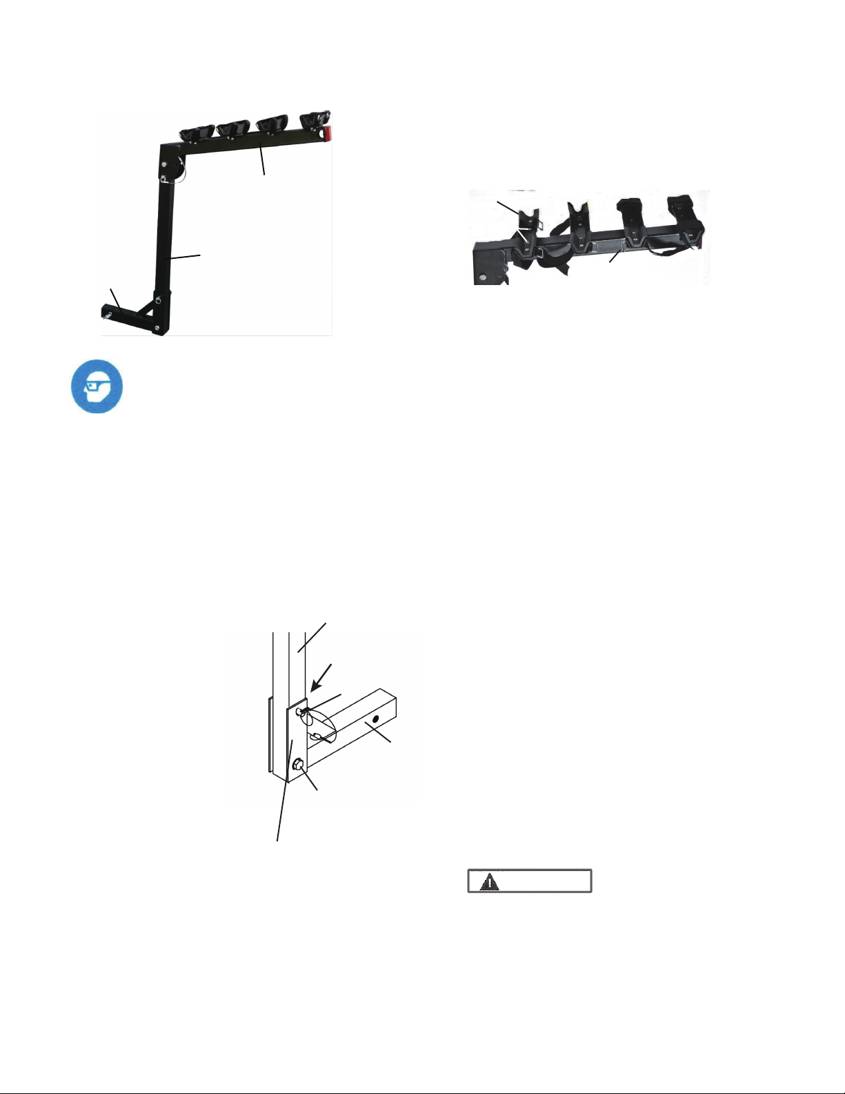
3. Use of the Bike Rack
A. Model 70210 Bike Rack must be at-
tached to a 2” x 2” Class III or Class IV
hitch receiver.
The vehicle’s hitch receiver must be properly
installed by a qualied service technician
and be certied to support the weight of this
Bike Rack and its contents (Model 70210
maximum weight capacity of four bikes =
150 Lbs.).
B. Do not modify the Bike Rack and do
not use this product for purposes that it
was not designed for.
C. Never exceed the maximum weight
capacity shown in paragraph A above.
D. Be aware of the danger of “dynamic
loading”. This situation arises when a load
is dropped onto the Bike Rack, resulting in a
short term excessive load. Dynamic loading
can result in damage and failure of the Bike
Rack and/or hitch receiver, and personal
injury to the person loading the Bike Rack.
E. Never load people or animals onto the
Bike Rack. Keep children and spectators
well clear when loading, unloading and using
this product.
F. Adhere to all Department of Transpor-
tation (D.O.T.) requirements when using
this product. Always use the Bike Straps to
securely hold the bicycles in place.
G. For the vehicle that will support the Bike
Rack, read all pertinent vehicle instructions
and warnings provided in the owner’s
manual. Make sure the vehicle’s engine is
OFF, with parking brake set, before load-
ing or unloading the Bike Rack.
H. Note the position of the vehicle’s
exhaust pipes before setting up the Bike
Rack. Make sure exhaust pipes are not in
close proximity to the loaded bicycles. Flam-
mable goods loaded on the Bike Rack could
catch on re due to heat from exhaust. If
this risk exists on your vehicle, do not use
the Bike Rack.
I. Do not use this Bike Rack on a trailer or
5th wheel R.V. Do not use with bicycles t-
ted with large accessories (such as a child
carrying seat). Do not exceed 55 MPH ve-
hicle speed when Bike Rack is attached.
J. Always check slide pins, cotter pins and
Lock Pin for tightness prior to each trip. Re-
place Bike Straps annually, or at rst signs of
wear.
K. Do not operate vehicle unless Bike
Rack is in the upright position. When not
in use, remove Bike Rack from the vehicle
and store indoors.
Keep in mind that the warnings previ-
ously discussed cannot cover all pos-
sible conditions or situations that could
occur. It is important that the person
loading/unloading and using this product
understand that common sense and cau-
tion are factors which cannot be built into
this product, and must be supplied by the
operator.

Model 70210 Page 4
Assembling and Setting Up
the Bike Rack
1. Refer to photo above of an already as-
sembled Bike Rack, and to the Assembly
Diagram at end of this manual.
3. Connect 4 Bike Brackets (3) to top side
of Arm Bar (8). Each Bike Bracket is held
4. Assemble Arm Bar (8) to Post (26).
5. With assembly complete, check for tight-
ness of Bolts, Lock Nuts, R-Pins and Lock-
ing Knob, before attaching Bike Rack to
vehicle’s hitch receiver.
6. With assistance, Lift the Bike Rack and
slide the end of the Hitch Tube (28) into
the vehicle’s hitch receiver. Align the hole
openings and secure the Bike Rack to the
vehicle with the Hitch Bolt (19). Secure the
Hitch Bolt with R-Pin (20).
Using the Bike Rack
1. Make sure the vehicle
is in a safe place for loading bicycles.
Make sure the vehicle’s engine is OFF,
with parking brake set, before loading or
unloading the Bike Rack.
Always wear ANSI approved
safety goggles.
Post (26)
Pin (15)
Bolt (25),
2 Flat Washers (27),
Lock Nut (12)
U-Shape Bracket
Hitch Pin
(28)
Post (26)
Arm Bar (8)
Hitch Tube
(28)
Rrm Bar (8)
Bike Bracket (3)
Bolt (4)
WARNING
Rubber
Plug (29)
2. Attach Post (26) to the Hitch Tube (28).
Slide Flat Washer (27) on Bolt (25) and
insert Bolt through lower hole opening.
Place another Flat Washer (27) and Lock
Nut (12) on the Bolt, not tighten the Bolt and
Nut. See photo to below.
Insert lower portion of
Post into lower bracket of
Hitch Tube. With assist,
press the Post to agaist
the Rubber Plug (29),
and further press down a
little, so you are able to
line up hole openings
and insert Pin (15) into
upper hole. Secure Pin
with Small R-Pin (16).
Tighten the Bolt (25) and
Lock Nut (12) till no gap between the Post
and U-Shape Bracket. Do not overtighten
the Bolt and Nut make sure the Post can
be swing back smoothly when removing
the Pin (15).
in place with 2 Bolts (4) and 2 Lock Nuts
(7). Tighten hardware securely. See photo,
upper right.
Slide Flat Washer (27) on Bolt (25), align hole
openings and insert Bolt (25) through the
upper hole opening. Secure Bolt with another
Flat Washer (27) and Lock Nut (12).
Insert Pin (15) through lower hole opening
and secure with Small R-Pin (16), to position
Arm Bar in the horizontal position (for bike
loading).
With Pin (15) and Small R-Pin (16) removed,
the Cross Bar can be folded down to vertical
position when attaching to vehicle hitch
receiver, or when bicycles are removed.

Model 70210 Page 5
SPECIFICATIONS
Maximum Weight
Capacity
150 Lbs.
For Use With 2” x 2” Class III and IV
Hitch Receivers;
Application Holds up to 4 bicycles.
Included
2. Put Arm Bar (8) in horizontal position,
and lock it in place with Pin (15) and Small
R-Pin (16).
3. Open the hook and loop attachment on
Bike Straps (5).
4. Lift and place the bicycle’s upper frame
on the Rubber Block (2) portion of the Bike
Bracket (3). Secure the bike in place with
the Bike Strap hook and loop attachment.
5. Add additional bicycles if desired. Cau-
tion: Make sure bicycle frames and wheels
are positioned so that they will not rub
against each other, or the vehicle, and cause
paint damage during transit. If needed,
secure bicycle wheels with straps or rope to
prevent movement.
6. Do not overload the
Bike Rack (maximum 4 bikes with maxi-
mum weight capacity of 150 Lbs. total).
7. When the Bike Rack is not needed, it
should be removed from the vehicle and
stored indoors.
WARNING
Never operate the vehicle when Bike Rack
is in this lowered position. Do not operate
vehicle unless Bike Rack is in the upright
position.
Maintaining the Bike Rack
1. Frequently check the condition of the
Bike Rack and the vehicle’s hitch receiver.
Make sure all components are in good
condition. If the Bike Rack or hitch receiver
become damaged through accident, or if any
weld damage is noted, the product should be
replaced.
2. Check to make sure that all hardware is
tightly secured in place. Keep the Bike Rack
clean.
Pin (15) removed
from locked
position.
Limited Warranty. Maxx Group LLC warrants
to the original retail purchaser that the product
is free of defects in material and workman-
ship at the time of shipment. This product
is warranteed for 90 days from the date of
purchase. This warranty is expressly in lieu
of all other warranties, express or implied.
Proof of purchase is required for warranty
transactions; a copy of the original invoice
or sales receipt is required.
8. The empty Bike Rack can be lowered
to the position shown in photo below if the
vehicle’s tail gate needs to be temporarily
opened before any bicyles are attached.
Remove Small R-Pin (16) and Pin (15),
and carefully tilt back the Bike Rack when
additional clearance is needed.

Model 70210 Page 6
Assembly Diagram
Parts List
Note: The Parts List and Assembly Diagram is provided as a reference tool only.
Some parts are listed and shown for illustration purposes only, and are not available
as replacement parts. All repairs to this tool (including replacing parts) should only
NO Description Qty NO Description Qty
1 Screw 8 14 Ring 4
2 Rubber Block 8 15 Pin 2
3 Bike Bracket 4 16 Small R-Pin 2
4 Bolt 8 17 Cable 2
5 Bike Strap 8 19 Hitch Bolt 1
6 Flat Washer 8 20 R-Pin 2
7 Lock Nut 16 25 Bolt 2
8 Arm Bar 1 26 Post 1
9 Reflector 1 27 Flat Washer 4
10 Spring Washer 2 28 Hitch Tube 1
11 Nut 2 29 Rubber Plug 1
12 Lock Nut 2
Manufactured and Distributed by:
Maxx Group, LLC,
Camarillo, CA93012, USA
www.maxxhaul.com
1
2
4
8
12
27
25
17
14
16 15
26
22 28
19
17
14
15
16
25
27
27
12
29
3
5
6
7
10 11
7
9
Table of contents
Other Maxxhaul Automobile Accessories manuals

Maxxhaul
Maxxhaul 50130 User manual

Maxxhaul
Maxxhaul 70468 User manual

Maxxhaul
Maxxhaul 50218 Instruction Manual

Maxxhaul
Maxxhaul 50616 User manual

Maxxhaul
Maxxhaul 70214 Instruction Manual

Maxxhaul
Maxxhaul 70229 User manual

Maxxhaul
Maxxhaul 50241 Instruction Manual

Maxxhaul
Maxxhaul 70209 User manual

Maxxhaul
Maxxhaul 80401 User manual

Maxxhaul
Maxxhaul 50220 User manual
Popular Automobile Accessories manuals by other brands

Cruz
Cruz N+ Series Assembly instructions

Thule
Thule RAPID TRACKER 4712 Fitting instructions

Mont Blanc
Mont Blanc 837 Fitting instructions

Carefree
Carefree Alpine Slideout Cover Service manual

BrandMotion
BrandMotion 9002-7710 installation instructions

Kuda-Phonebase
Kuda-Phonebase 291770 Installation instruction