Installation and Operating Instructions for
EAS®-NC clutch Type 45_. _ _ _ . _ Sizes 02 and 03 (B.4.8.2.1.GB)
13/02/2009 TK/KR/GC Chr. Mayr GmbH + Co. KG Tel.: 08341 / 804-241
Eichenstraße 1 Fax: 08341 / 804-422
D-87665 Mauerstetten http://www.mayr.de
Page 5 of 10 Germany eMail: info@mayr.de
Assembly of the output elements (Figs. 1 and 3)
Please Observe!
Observe thread diameter and max. reach of
screw in the pressure flange (2) according
to Table 2.
In case of the EAS®-NC Type 450.- the output element is
located on the deep groove ball bearing (6) and screwed with the
pressure flange (2).
If the resulting radial force of the output element is nearly in the
centre of the ball bearing (7) an additional bearing of the output
element is not required.
In case of very wide output elements and a force application of
the resulting radial force outside the bearing centre, the output
element is additionally located on the shaft, Fig. 3.
Ensure that no significant axial forces (see Table 2) are
transmitted from the output element onto the pressure
flange (2) of the clutch.
For extremely wide output elements or for elements with a small
diameter, the EAS®-NC with long projecting hub is
recommended (Type 450._ _ _.1).
In the case of a very small diameter the output element is
attached to the pressure flange (2) of the clutch via an
intermediate adapter flange provided by the customer.
Ball bearings, needle bearings or bearing bushings are suitable
as bearing for the output element depending on the mounting
situation and installation facility.
Ensure that the bearing of the output element is designed as
location bearing (Fig. 3).
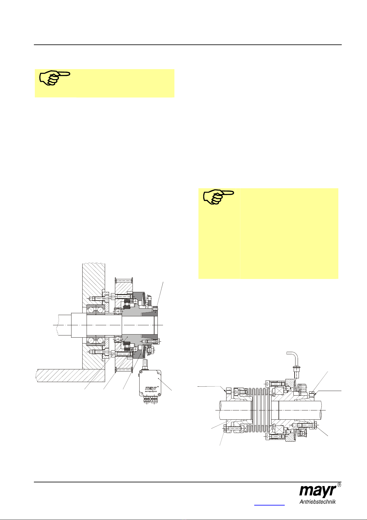
Fig. 3
Type 450.61_.0
Attachment onto the shaft
The EAS®-NC clutches are supplied with cone bushings or
keyways already fitted as standard.
Following points have to be noticed for the assembly of
cone bushings:
Shaft fits: h6 up to k6,
Surface of the shafts:
fine turned or ground (Ra = 0,8 µm)
Shaft material: yield point at least 400 N/mm2,
e.g. St 60, St 70, C 45, C 60.
Shafts and bores must be degreased or the preservation is to
be washed off before installation of the clutch or clutch hubs.
Greasy or oily bores or shafts do not transmit the torque
TRindicated in the order.
Push the clutch or clutch hub onto both shaft ends with a
suitable device and bring them to the correct position.
Uniformly tighten the clamping screws one after another (in 3
to max. 6 tightening circulations) using a torque wrench to the
torque indicated in Table 2.
Please Observe!
The clutch or clutch hub executes an axial
displacement in direction of the cone
bushing when tightening the cone bushing.
In case of the EAS®-NC clutch with steel
bellows (Type 453._ _ _.0) it must be
observed that at first only one cone bushing
is completely tightened (e.g. component
13/22), and then the other (steel bellows)
side (component 20/21, Fig. 5) because of
the above mentioned effect.
Additionally it must be observed when
assembling the Type 453._ _ _.0, that no
axial pressure is exerted on the steel
bellows (damage).
Disassembly
There are extractor threads beside of clamping screws
(13 and 20) in the cone bushings.
1) Release all clamping screws by several threads.
2) Unscrew the clamping screws located beside the extraction
threads and screw them into the extraction threads until
contact. Afterwards tighten these screws until the clamping
connection is released.
Fig. 5
2 3
21
thread
Extraction
thread