30119-03 Rev. 3.8/06-05
McCrometer • Page 5
CONFIGURATION METHODS:
All configurations are user defined and password protected.
The configuration is stored in nonvolatile memory with a 10-
year retention. The converter is fully programmed before ship-
ping. Reprogramming can be easily done on site using the fol-
lowing methods:
KEYPAD – can be used to access and change all menu param-
eters using four membrane keys and 3-line display.
RS232 – standard 9-pin data connection for local hand-held
terminal or computer (null modem/Lap Link cable required). Soft-
ware such as ProComm Plus or Microsoft Windows Hyper Ter-
minal is required (see page 29).
HART™Communication – Optional.
DISPLAY:
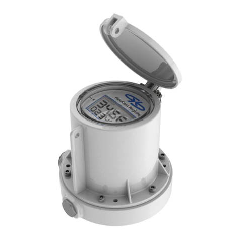
Back Lit: 3-line, 16-character, read only display for flowrate
(in a choice of engineering units and % of range), forward to-
talizer, reverse totalizer, net totalizer, alarm conditions, flow
velocity, and percent of range.
Internal Totalizer: Resettable 9-digit for forward, reverse
and net totals. Can be programmed to reset via external in-
put.
Test Mode and Output Circuit Loop Verification: After
converter has been programmed, operation of the test mode
will drive all outputs to programmed value to provide total
system test.
INTERCHANGEABILITY: Converters are fully interchangeable with
all sizes of UltraMag sensors and configurable on site. Sys-
tem specification not affected by converters change.
TIME CONSTANT: Fully programmable from 2 to 120 secs
(page 24).
IV. INSTALLATION:
McCrometer's UltraMag Meters are normally supplied as a
calibrated system with the converter factory calibrated to
the supplied sensor. The meter must have a full flow of
liquid for proper accuracy. Installation is made in the fol-
lowing manner:
1. POSITIONING THE SENSOR: The following installa-
tion recommendations should be followed (see page 7 for
installation diagrams):
A. In horizontal pipe runs, the electrodes should be
in a horizontal plane to prevent coating by sediments or
loss of electrode contact due to air bubbles.
B. In vertical pipe runs, the flow should be upward.
In slurry application, a vertical position ensures optimal
distribution of solids under all flow conditions.
C. It must be ensured that the sensor is always
completely filled with liquid.
D. For proper accuracies any 90 or 45 degree el-
bows, valves, partially opened valves etc. should be
placed not closer than five to ten pipe diameters up-
stream and two pipe diameters downstream.
E. The flow of the medium should correspond to the
direction shown by the arrow on the sensor.
2. ELECTRICAL NOISE AND SENSOR: For flow mea-
surement free of electrical noise interference, the sensor
body must have electrical contact with the media. This is
normally achieved via a required grounding ring (see page 8
for diagram).
3. FLUID CONDUCTIVITY: To eliminate rapid changes in
fluid conductivity, all blending and chemical injecting should
be done early enough so the flow media is thoroughly mixed
prior to entering the measurement area.
4. METER LOCATION: Adjoining pipe must be ad-
equately supported and area around sensor should provide
sufficient drainage to prevent flooding the converter or con-
duits.
The location chosen should provide room to read the display
and be free from harsh electrical noise from adjacent equip-
ment, cables, R.F.I., or E.M.I. The signal converter should not
be subjected to intense, prolonged sunlight, dripping fluids or
spillage, and/or vibrations. Unit should also be shaded from
heat.
5. REMOTE MOUNT SIGNAL CONVERTER may be in-
stalled in the desired place. Providing that free access is
available to allow the display to be viewed as required, the
unit can be either wall mounted or panel mounted with ma-
sonry fixings or nuts and bolts respectively via the fixing
holes provided. Max distance of 300 feet from sensor.
6. GROUNDING RING & GASKETS must be used to en-
sure seal at the flanges and to ensure fluid is properly
grounded to sensor (see page 8).
7. CONVERTER/TRANSMITTER CONNECTIONS to the
sensor must be made with cable supplied by McCrometer
specifically for that purpose. Do not substitute the supplied
cable with other types of cable, even for short runs. For
repairs or added lengths of cable, the entire cable between
the sensor and the converter must be replaced. (Consult
factory for replacement cable and potting compound.)
Power Supply to the converter must be single phase rated at
no more than 265 volts for AC powered converters. This
supply must be fitted with a means of disconnection and be
fused with a fuse suitable for the cable employed but not
exceeding 35 amps.
The converter is not designed to accept rigid conduit direct
entry. If rigid conduit is employed, the first few feet must be
run in flexible conduit and the converter be fitted with face
sealing cable glands. Only 1/2" NPT glands and adapters
may be used.
Only the specified cables and adaptors may be fitted, and in the
manner described elsewhere in this manual. The required NEMA
Enclosure Rating must be maintained. It may be necessary to
seal the conduit entry to prevent moisture entering the terminal
box via the conduit. Potting the junction box is recommended
for remotely mounted converters. Some of these options may
not be suitable for a particular installation. For example, if
mechanical damage to the cable could occur, only armored cable
or conduit should be used. Obey local and national require-
ments for wiring and installation.
