en
it
de
es
fr
nl
pt
da
no
sv
pl
ru
cs
hu
sl
tr
hr
lt
lv
et
ro
sk
bg
uk
bs
el
zh
IMPORTANT: READ AND UNDERSTAND THIS OPERATIONAL MANUAL
PRIOR TO ASSEMBLING, STARTING UP OR CONDUCTING MAINTENANCE
ON THIS HEATER. USING THE HEATER INCORRECTLY CAN CAUSE
SERIOUS OR FATAL INJURIES. KEEP THIS MANUAL FOR FURTHER
REFERENCE.
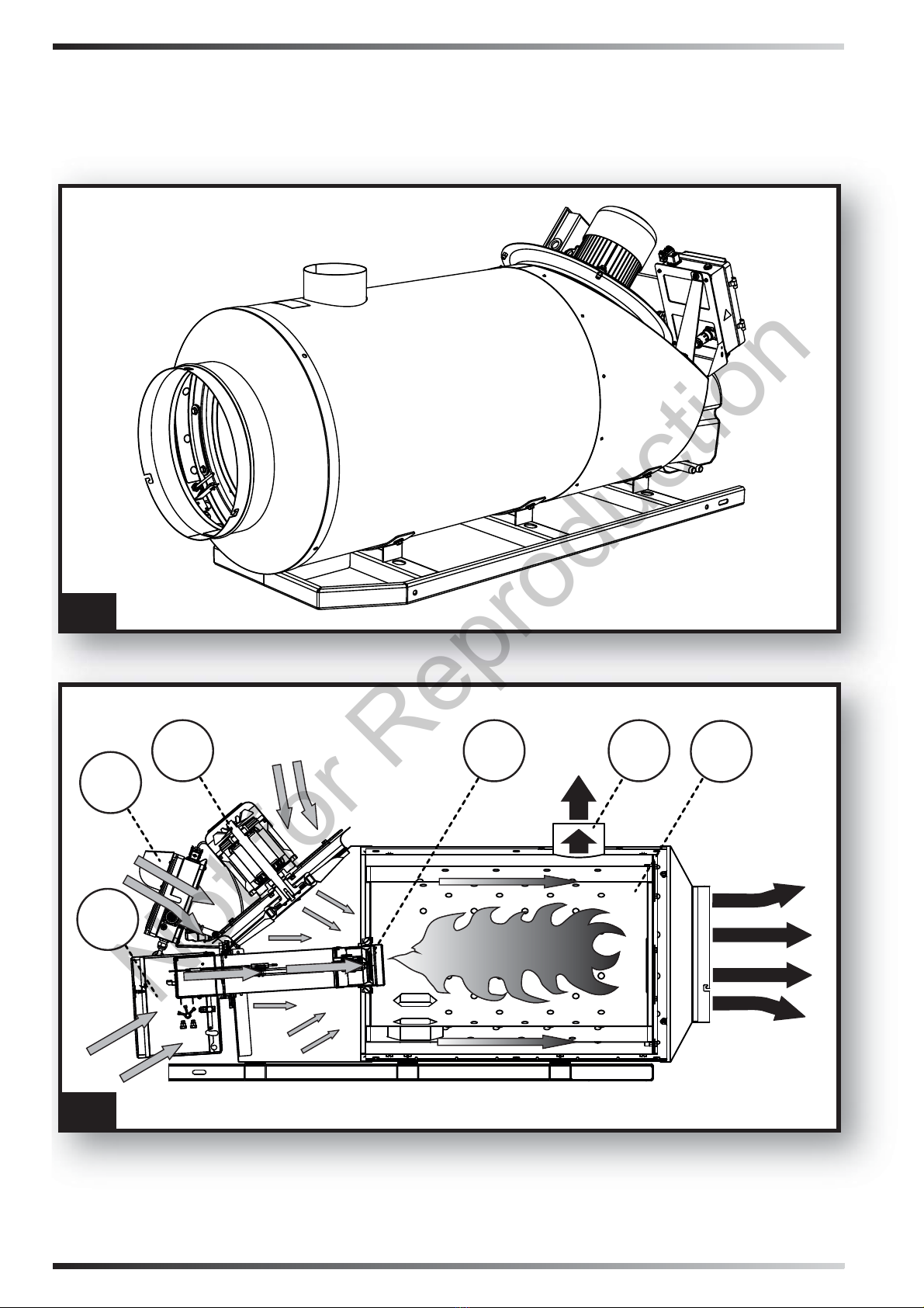
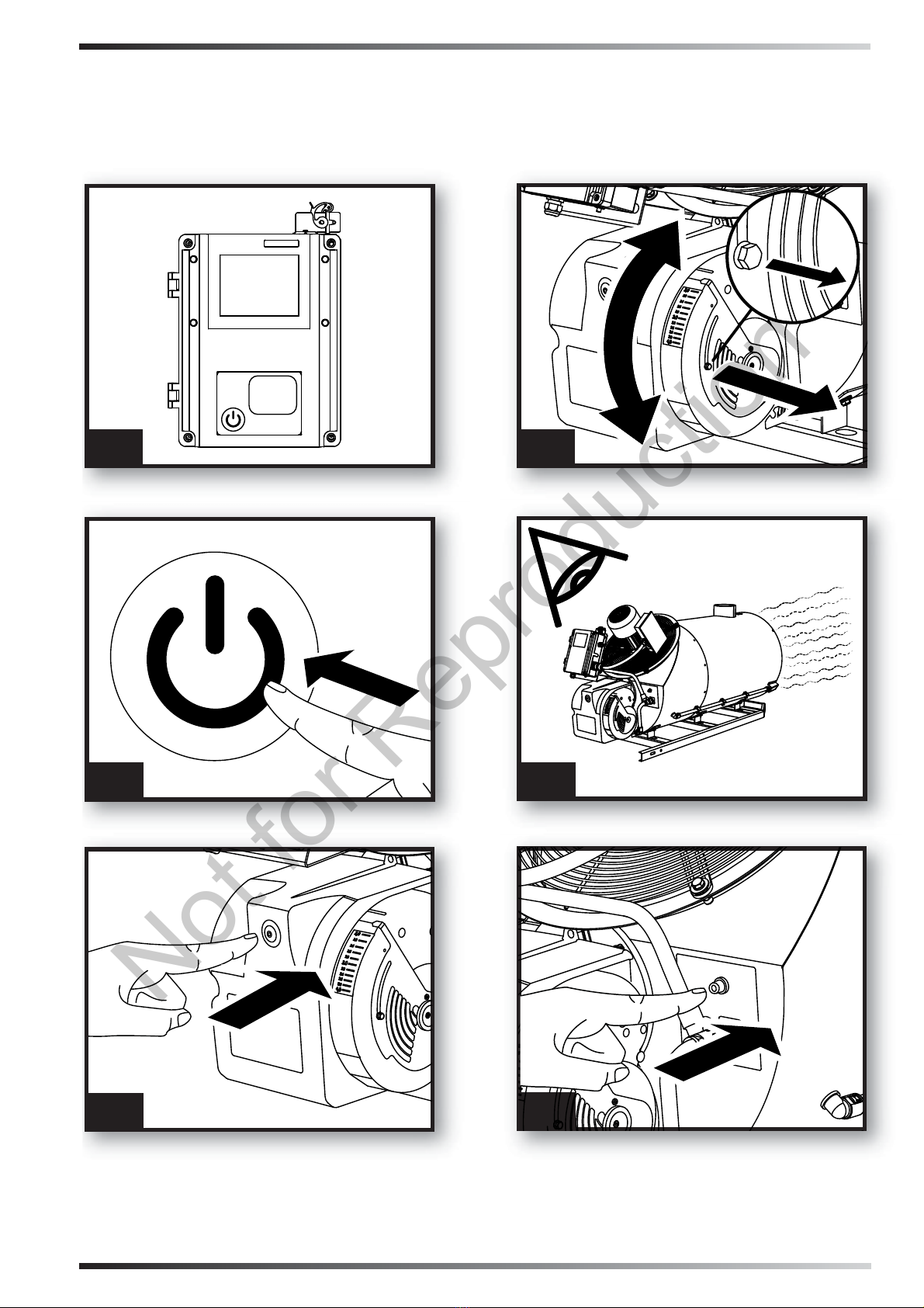
1. DESCRIPTION
(Pic. 1) This heater is equipped with a dedi-
gas evacuation to the outside and a high per-
formance hot air handling fan. Depending on
the model, the heater can be provided with an
electronic control system. The air is heated by
thermal energy produced by combustion trans-
mitted by means of thermal exchange with the
metal surfaces of the combustion chamber
separated by metal surfaces joined by welds
and gaskets. The combustion products are
conveyed to an exhaust duct. This must be
the air required for combustion, is drawn di-
rectly from the burner, which draws it from the
surrounding environment. Its size and work
conditions must guarantee an appropriate air
exchange.
2. SAFETY INFORMATION
WARNINGS
!IMPORTANT: This appliance is not su-
itable for use by persons (including child-
ren) with reduced physical, sensory or
mental capacities or who lack experience
or knowledge unless supervised by a per-
son responsible for their safety. Children
must be supervised to make sure they do
not play with the appliance.
!DANGER: Suffocation by carbon
monoxide can be fatal.
-
headache, light-headedness and/or nausea.
These symptoms could be caused by the
faulty functioning of the heater. IF THESE
SYMPTOMS OCCUR, GO OUTDOORS IM-
MEDIATELY and have the heater repaired by
an authorised technical support centre.
2.1. REFUELLING:
•••2.1.1. Personnel appointed to carry out
-
miliar with the manufacturer's instruc-
tions and current regulations on how to
refuel heaters safely.
•••2.1.2. Only use the type of fuel expressly
technical data label app-
lied to the heater.
•••2.1.3. The tanks used to store the fuel
must be stored in a separate place.
•••2.1.4. Fuel tanks must be kept at a mini-
mum distance from the heater, in accor-
dance with current standards.
•••2.1.5. The fuel must be stored in an area
-
which may ignite the fuel.
•••2.1.6. The fuel must be stored in accor-
dance with current regulations.
2.2. SAFETY:
•••2.2.1. -
ment is available and suitable to the po-
tential of the heater.
•••2.2.2. Never use the heater in areas with
petrol, paint solvents or other highly
•••2.2.3. Comply with all local legislation
and current regulations when using the
heater.
•••2.2.4. Heaters used near tarpaulins, cur-
tains or other similar covering materials
must be a safe distance from them. It is
-
rial.
•••2.2.5. Only use in well-ventilated areas.
Set-up a suitable opening in line with cur-
rent standards, with the purpose of intro-
ducing fresh air from outdoors.
•••2.2.6. Power on the heater only with a
current which has the voltage and fre-
data label applied to the heater.
•••2.2.7. Only use extension cables that
have an earth.