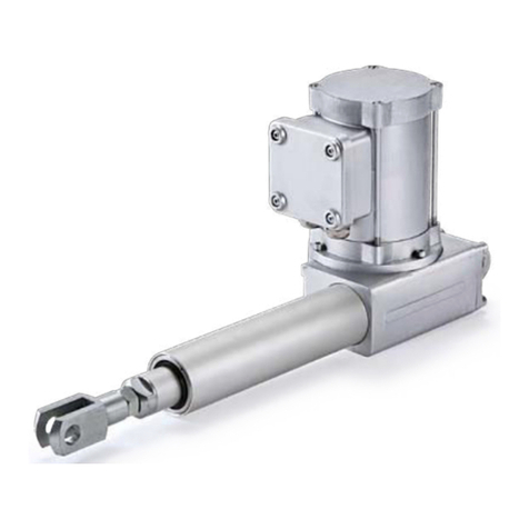
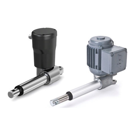
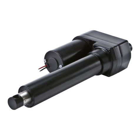
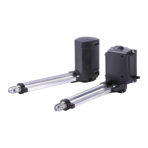
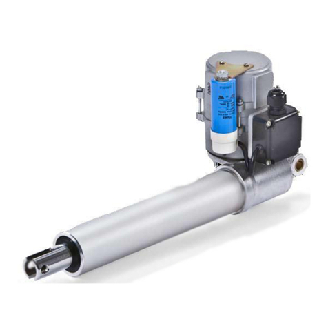
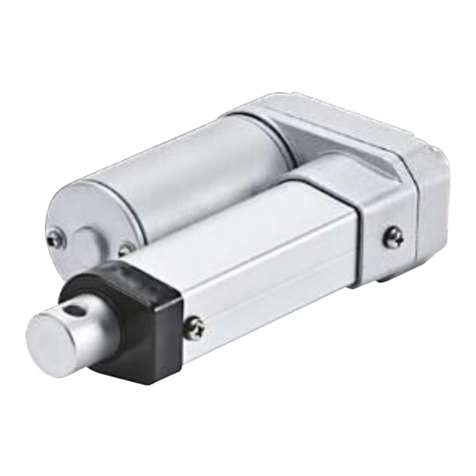
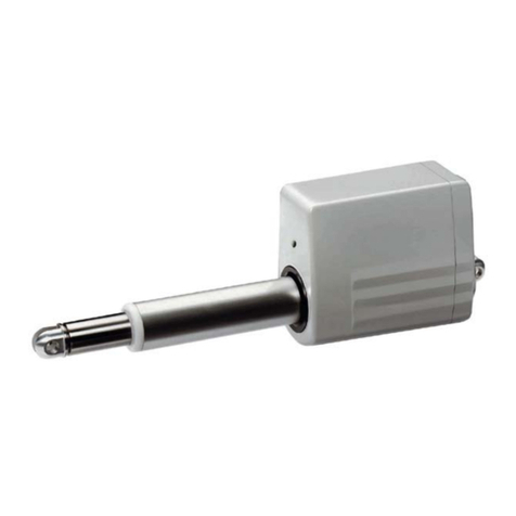
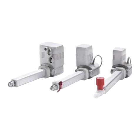
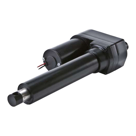
SKF CAHB-20E User manual

Installation, operation and maintenance manual
CAHB-20 series
Linear actuator CAHB-20E, CAHB-21E and CAHB-22E
WARNING
Read this manual before installing, ope-
rating or maintaining this actuator. Fai-
lure to follow safety precautions and
instructions could cause actuator failure
and result in serious injury, death or
property damage.


Contents
General information . . . . . . . . . . . . . . . . . . . . . . . . . . . . . . . .
1.1 Information on this manual . . . . . . . . . . . . . . . . . . . . . . . . . . 5
1.2 Explanation of symbols and signal words . . . . . . . . . . . . . . . 5
1.3 Limitation of liability . . . . . . . . . . . . . . . . . . . . . . . . . . . . . . . . 6
1.4 Warranty terms. . . . . . . . . . . . . . . . . . . . . . . . . . . . . . . . . . . . 7
1.5 Customer service . . . . . . . . . . . . . . . . . . . . . . . . . . . . . . . . . . 7
Safety . . . . . . . . . . . . . . . . . . . . . . . . . . . . . . . . . . . . . .
2.1 Limitation of liability . . . . . . . . . . . . . . . . . . . . . . . . . . . . . . . . 8
2.1.1 Intended use . . . . . . . . . . . . . . . . . . . . . . . . . . . . . . . . . . . . 8
2.2 Responsibility of the owner and processor . . . . . . . . . . . . . . 8
2.2.1 Qualifications . . . . . . . . . . . . . . . . . . . . . . . . . . . . . . . . . . . . 9
2.2.2 Specific dangers. . . . . . . . . . . . . . . . . . . . . . . . . . . . . . . . . . 10
2.3 Safety equipment . . . . . . . . . . . . . . . . . . . . . . . . . . . . . . . . . . 11
2.4 Changes and modifications on the actuator. . . . . . . . . . . . . . 12
Technical data . . . . . . . . . . . . . . . . . . . . . . . . . . . . . . . .
3.1 Operating conditions. . . . . . . . . . . . . . . . . . . . . . . . . . . . . . . . 14
3.2 Operating voltages and limits. . . . . . . . . . . . . . . . . . . . . . . . . 15
3.3 Product label. . . . . . . . . . . . . . . . . . . . . . . . . . . . . . . . . . . . . . 15
Structure and function . . . . . . . . . . . . . . . . . . . . . . . . . .
4.1 Overview . . . . . . . . . . . . . . . . . . . . . . . . . . . . . . . . . . . . . . . . . 16
4.2 Brief description . . . . . . . . . . . . . . . . . . . . . . . . . . . . . . . . . . . 18
4.3 Special features . . . . . . . . . . . . . . . . . . . . . . . . . . . . . . . . . . . 19
4.5 Connection . . . . . . . . . . . . . . . . . . . . . . . . . . . . . . . . . . . . . . . 20
4.6 Options . . . . . . . . . . . . . . . . . . . . . . . . . . . . . . . . . . . . . . . . . . 20
4.6.1 Limit switch . . . . . . . . . . . . . . . . . . . . . . . . . . . . . . . . . . . . . 20
4.6.2 Potentiometer . . . . . . . . . . . . . . . . . . . . . . . . . . . . . . . . . . . 21
4.6.3 Encoder . . . . . . . . . . . . . . . . . . . . . . . . . . . . . . . . . . . . . . . . 21
4.6.4 Manual Override . . . . . . . . . . . . . . . . . . . . . . . . . . . . . . . . . 22
Transport, packaging and storage. . . . . . . . . . . . . . . . . .
5.1 Safety information for the transport . . . . . . . . . . . . . . . . . . . 23
5.1.1 Transport inspection . . . . . . . . . . . . . . . . . . . . . . . . . . . . . . 23
5.1.2 Return to the manufacturer . . . . . . . . . . . . . . . . . . . . . . . . 24
5.1.3 Packaging. . . . . . . . . . . . . . . . . . . . . . . . . . . . . . . . . . . . . . . 24
5.2 Storage . . . . . . . . . . . . . . . . . . . . . . . . . . . . . . . . . . . . . . . . . . 25
Installation and first operation . . . . . . . . . . . . . . . . . . . .
6.1 Installation location. . . . . . . . . . . . . . . . . . . . . . . . . . . . . . . . . 27
6.2 Installation . . . . . . . . . . . . . . . . . . . . . . . . . . . . . . . . . . . . . . . 27
6.3 Inspections prior to first operation . . . . . . . . . . . . . . . . . . . . . 29
6.4 Connect to power supply . . . . . . . . . . . . . . . . . . . . . . . . . . . . 29
6.4.1 Wiring scheme for no Limit Switch option: . . . . . . . . . . . . . 30
Operation . . . . . . . . . . . . . . . . . . . . . . . . . . . . . . . . . . .
7.1 Safety . . . . . . . . . . . . . . . . . . . . . . . . . . . . . . . . . . . . . . . . . . . 31
7.2 Action before operation . . . . . . . . . . . . . . . . . . . . . . . . . . . . . 32
7.3 Action during operation . . . . . . . . . . . . . . . . . . . . . . . . . . . . . 32
7.3.1 Normal operation. . . . . . . . . . . . . . . . . . . . . . . . . . . . . . . . . 33
7.4 Disengagement in case of emergency . . . . . . . . . . . . . . . . . . 35
7.5 Action after use . . . . . . . . . . . . . . . . . . . . . . . . . . . . . . . . . . . . 35
Maintenance . . . . . . . . . . . . . . . . . . . . . . . . . . . . . . . . .
8.1 Spare parts . . . . . . . . . . . . . . . . . . . . . . . . . . . . . . . . . . . . . . . 36
8.2 Maintenance plan . . . . . . . . . . . . . . . . . . . . . . . . . . . . . . . . . . 37
8.3 Maintenance work . . . . . . . . . . . . . . . . . . . . . . . . . . . . . . . . . 38
8.3.1 Cleaning . . . . . . . . . . . . . . . . . . . . . . . . . . . . . . . . . . . . . . . . 38
8.3.2 Inspections and readings . . . . . . . . . . . . . . . . . . . . . . . . . . 38
8.3.3 Check of visual condition . . . . . . . . . . . . . . . . . . . . . . . . . . . 39
8.4 Measures after completed maintenance . . . . . . . . . . . . . . . . 39
Malfunctions . . . . . . . . . . . . . . . . . . . . . . . . . . . . . . . . .
9.1 Malfunction table . . . . . . . . . . . . . . . . . . . . . . . . . . . . . . . . . . 42
9.2 Start of operation after fixing malfunction. . . . . . . . . . . . . . . 43
Dismantling . . . . . . . . . . . . . . . . . . . . . . . . . . . . . . . .
10.1 Dismantling. . . . . . . . . . . . . . . . . . . . . . . . . . . . . . . . . . . . . . 44
10.1.1 Dismantling of CAHB-20A. . . . . . . . . . . . . . . . . . . . . . . . . 45
10.2 Disposal . . . . . . . . . . . . . . . . . . . . . . . . . . . . . . . . . . . . . . . . 45
Appendix . . . . . . . . . . . . . . . . . . . . . . . . . . . . . . . . . . .
3
4

1 General information
NOTE
Emphasizes useful hints and recom-
mendations as well as information
for efficient and trouble-free operation.
CAUTION
Indicates a dangerous situation, which
can lead to minor or moderate personal
injury or property damage, if the pre-
cautionary measures are ignored.
WARNING
Indicates a dangerous situation, which
can lead to severe personal injury or
death, if the precautionary measures
are ignored.
DANGER
Indicates a dangerous situation, which
will lead to death or severe personal
injury, if the precautionary measures
are ignored.
1.1 Information on this
manual
This manual provides important information on how to work with
the actuator safely and efficiently.
The manual is part of the actuator, must always be kept in the
actuator’s direct proximity and should be available for the personnel
at any time. All personnel working with the actuator must read and
understand this manual before starting any work. Strict compliance
with all specified safety notes and instructions is a basic requirement
for safety at work.
Moreover, the accident prevention guidelines and general safety
precautions applicable at the place of use of the actuator must also
be complied with.
For better representation of circumstances, the illustrations used
are not necessarily to scale and may vary from the actual design of
the actuator.
1.2 Explanation of symbols
and signal words
Safety precautions
Safety precautions are identified by symbols and signal words.
These signal words indicate the severity of the hazard.
Adhere to these safety precautions and act cautiously in order to
avoid accidents, personal injuries and damage to property.
5

1.3 Limitation of liability
All information and notes in this manual were compiled under due
consideration of valid standards and regulations, the present status
of technology and our years of knowledge and experience.
The manufacturer will not be liable for damage resulting from:
• disregarding this manual
• unintended use
• employment of untrained personnel
• unauthorized conversions
• technical modifications
• manipulation or removal of the screws on the actuator
• use of unapproved spare parts
In case the actuator is customised, the actual product delivered may
be different from what is described in the manual. In this case, ask
SKF for any additional instructions or safety precautions relevant to
these actuators.
We reserve the right to make technical modifications to the actua-
tor to improve usability.
6

1.4 Warranty terms
The applicable and effective warranty terms are those contained in
the manufacturer’s terms and conditions of sale.
1.5 Customer service
SKF Customer Service is always available to provide technical infor-
mation and answer questions.
The contact information for SKF Customer Service can be found
on www.SKF.com.
7

2 Safety
2.1 Limitation of liability
This chapter provides an overview of important safety precautions
and information necessary for safe and trouble-free installation,
operation and maintenance.
Disregarding this Manual and safety precautions specified therein
may result in considerable danger and possible serious injury or
death.
2.1.1 Intended use
The actuator has been designed and built exclusively for its intended
purpose as described in these instructions.
WARNING
Risk from misuse!
Any utilization of this actuator beyond its intended purpose may
lead to potentially hazardous situations.
Therefore:
• Strictly adhere to all safety precautions and instructions in this
manual.
• Do not allow this actuator to be subjected to weather condi-
tions, strong UV rays, corrosive or explosive air media as well
as other aggressive media.
• Do not modify, retool or change the structural design or indi-
vidual components of the actuator.
• Never use the actuator outside of the technical application and
operational limits.
Any injury, damage or loss caused by violation of these instructions
will be the responsibility of the customer.
2.2 Responsibility of the
owner and processor
The actuator is designed for personal use and is also used in com-
mercial applications by owner or processors.
The processor is the contracting partner of the reseller or the
manufacturer. The processor installs the actuator in a complete sys-
tem (application).
The owner of the system is therefore subject to requirements of
the Occupational Health and Safety Act.
8

In addition to the safety instructions in this Manual, the owner or
processor must do the following concerning these safety and acci-
dent prevention guidelines and environmental precautions regula-
tions applicable to the site of the system’s installation:
• Inform themselves of applicable industrial safety precautions and
determine additional hazards that arise due to the specific working
conditions prevailing at the site where the actuator is installed
using risk assessment. The risk assessment must be implemented
in the form of work instructions for the actuator operation.
• Confirm that the work instructions created for the system including
the actuator satisfy current legal requirements and must alter the
instructions if they don’t.
• Clearly regulate and specify the responsibilities for installation,
operation, maintenance, and cleaning.
• Ensure that all employees who deal with the actuator have read
and understood this Manual.
• Provide personnel with the required protective equipment.
In addition, owner must train personnel at regular intervals and
inform personnel of the hazards.
In addition, owner or processors must ensure that the actuator is
in an adequate working condition. They must do the following:
• Ensure that the maintenance intervals described in these instruc-
tions are complied with.
• Have all safety devices inspected regularly for function and
completeness.
WARNING
Risk from misuse!
Improper installation, operation and maintenance can result in
serious injury, death or property damage.
Use only qualified, instructed, or trained personnel (as described
below) who have read, understand and follow these instructions.
2.2.1 Qualifications
The following qualifications are specified for different areas of
activity listed in the Manual.
• An instructed person (Operator)
has been instructed by the customer in an orientation session on
the assigned tasks and possible dangers in case of improper
behaviour.
• Qualified personnel
based on their professional training, know-how and experience as
well as knowledge of the applicable standards and regulations is
able to perform assigned work activities and to detect and avoid
possible dangers on their own.
9

• A professional electrician
based on his/her professional training, know-how and experience
as well as knowledge of the applicable standards and regulations is
able to perform work on electrical systems and to detect and avoid
possible dangers on his/her own. The professional electrician has
been trained for the special location where he/she works and
knows the relevant standards and regulations.
Only persons who are expected to perform their tasks reliably are
permitted as personnel. Persons whose reaction capability is
impaired, e.g. through drugs, alcohol or medication, are not
permitted.
2.2.2 Specific dangers
The following section lists the residual risks that have been deter-
mined by the risk assessment.
• Heed the safety instructions listed here, and the warnings in sub-
sequent chapters of this Manual, to reduce health hazards and to
avoid dangerous situations.
DANGER
Danger to life caused by electric current!
Touching conductive parts causes a direct danger to life. Dam-
age to insulation or individual components can cause danger to
life.
Therefore:
• In the event of damage to insulation, switch off the power
supply immediately and have the parts repaired.
• Work on the electrical system must be carried out only by pro-
fessional electricians.
• De-energize the machine for all work on the electrical system.
• Before maintenance, cleaning or repair work, switch off the
power supply and perform lockout procedures so it cannot be
turned on again.
• Do not bridge fuses or make them ineffective. When changing
fuses, make sure you use the correct amperage.
• Keep moisture away from conductive parts. If you don’t, this
can cause short circuit.
Electric current
10

WARNING
Danger of injury caused by moving components!
Rotating and/or linearly moving components can cause severe
injury.
Therefore:
• Do not work on or place any of your body, hands, or arms near
moving components.
2.3 Safety equipment
WARNING
Danger due to malfunctioning safety equipment!
For safe operation, be sure all safety equipment is in good
working order.
Therefore:
• Always check functionality of safety equipment according to
the maintenance plan.
• Never disengage safety equipment.
• Safety equipment may never be by-passed or modified.
Integration in an emergency-stop system
required (for certain applications)
The actuator is only intended for installation into an an application or
system. It does not have its own operating control elements and does
not have an independent emergency-stop-function.
Install the actuator so that it is part of an emergency shut-off sys-
tem and can be stopped if necessary.
The emergency shut-off system has to be connected in such a
way that a disruption of the power supply or the reactivation of the
power supply after a power disruption cannot cause a hazardous
situation for persons and objects.
The emergency shut-off systems must always be freely accessible.
NOTE
The processor decides which applications require the
installation of an emergency shut-off system.
Moving components
11

The following safety features may have been
installed:
A thermal switch is integrated into the motor inside to prevent
damage from overheating. If overheating occurs when the actuator
is operating (over specification), the switch would be activated, the
power would be cut-off; after the temperature falls below the
threshold, the switch will restore..
CAUTION
To prevent damage from overheating, do not try to operate
actuator until its temperature has fallen below the threshold for
the switch to operate.
A driving screw nut converts the rotation of the gear unit into linear
motion. If an overload occurs when the actuator is operating, a ball
detent clutch will operate, thus stopping linear motion.
CAUTION
Continued operation of the clutch can result in overheating and
damage to the linear actuator. If clutch activates, switch off
power immediately.
Thermal switch
Overload protection
12

2.4 Changes and
modifications on the
actuator
To avoid hazardous situations and to ensure optimal performance,
do not make any changes or modifications to the actuator unless
they have been specifically authorized by SKF.
13

3 Technical data
3.1 Operating conditions
NOTE
The technical data (dimensions, weight, output, connection val-
ues etc.) can be found in the enclosed drawings and data sheets
(refer to chapter 11 Appendix).
Environment
Information Value Unit
Temperature range –40 to +85 °C
Relative atmospheric humidity,
maximum (no build up of condensation)
up to 96 %
V DC version – Duration (intermittent)
Information Value Unit
Maximum operating time without a break 1 Cycles
Break until next operation 4Times of
operating
time
Max duty cycle at rated load: 20% (85 s on / 340 s off)
V DC version – Duration (intermittent)
Information Value Unit
Maximum operating time without a break 1 Cycles
Break until next operation 9Times of
operating
time
Max duty cycle at rated load: 10% (85 s on / 765 s off)
14

Fig. The product label provides the following
information
1 Power voltage
2 Rated Load
3 Rated current
4 Speed
5 IP level
6 Duty cycle
7 Identification of actuator (type key)
8 Part number
9 Customer part number
10 Serial number
11 CE mark
12 Manufacturer or the country of origin
3.2 Operating voltages and
limits
The operating voltages and the limits for standard version, including
when PWM is used for speed ramp up refer to:
V DC version: supply voltage
• For actuator: 12VDC ± 20%
• For Encoder: 4-20VDC
• For Potentiometer: Voltage limited by power 2 W
V DC version: supply voltage
• No limit switch option: 24 V DC ±10%
• Encoder option: 4–20 V DC
• Potentiometer option: Voltage limited by power 2 W
3.3 Product label
15

4 Structure and function
4.1 Overview
Fig. CAHB-20 E without feedback
1 Front hinge head
2 Push tube
3 Guiding tube (Steel tube)
4 Motor
5 Cable
6 Rear hinge head
7 Gearbox
Fig.
CAHB- E
Include 3 types outline.
CAHB-20 E with feedback
8 Middle housing
Fig. CAHB- E with manual override
(Manual override option can be
configured on all series)
9 Manual override part
47
12 3
6
8
9
5
16

Fig. CAHB-21 E and 22 E without feedback
1 Front hinge head
2 Push tube
3 Guiding tube (Al alloy tube)
4 Motor
5 Cable
6 Rear hinge head
7 Gearbox
Fig.
CAHB- E and E
Include 3 types outline.
CAHB-21 E and 22 E with feedback
8 Middle housing
Fig. CAHB- E and E with manual
override (Manual override option can be
configured on all series)
9 Manual override part
4
7
12 3
6
5
8
9
17

4.2 Brief description
Fig. Overview
This actuator is to be used exclusively for installation into a dynamic
centric-compression or tensile-loaded lift.
The linear actuator consists of a motor part (), a gear unit () and
a linear unit (), connected with each other by a bayonet joint.
The actuator consists of a direct current motor with helical gear
which sets in motion a gear transmission system. Via the driving
screw and nut,the rotation of gear is transformed into a linear
motion of the actuator.
The front hinge head () and the rear hinge head () transmit the
actuator power to both sides of the application.
18

4.3 Special features
Mechanical overload protection
The actuator contains a mechanical overload protection unit (clutch).
This overload protection unit will activate if the linear unit of the
actuator overloads. This activation will avoid to push or pull over the
maximum force defined on the datasheet and will protect the motor
and gear unit from being damaged.
CAUTION
Continued operation of the clutch can result in overheating and
damage to the linear actuator. If clutch activates, switch off
power immediately.
CAUTION
To prevent damage from overheating when the actuator stop
with a high motor temperature, do not restart the actuator but
wait until the temperature decreases.
Gore automotive vent
The vent allows the equalization of the pressure inside the actuator
when it is operated, that will insure an optimum usage of the sealing
system
Thermal protection
The thermal switch built-in the motor will switch off the power of the
motor in case of over heat of the motor. It will automatically reset
when the temperature decreases.
Overload or more frequent operating the actuator over the max
duty cycles defined on the data sheet would lead to motor
overheating.
Fig.
0°
03°
06°
09°
120°
150°
0°
03°
06°
09°
120°
150°
19

4.5 Connection
Fig. CAHB-2… connections
1 Wires to connect actuator to power
supply or to an external control.
4.6 Options
If not specified otherwise, the options listed below are available for
the entire series of CAHB-2… linear actuators.
4.6.1 Limit switch
The limit switch makes it possible to control the stroke of the linear
unit by internal setting. Contact the SKF to adjust the setting of limit
switch.
Remark: Limit switch is not available for CAHB-20
4.4 Construction group
description
Motor
The motor is a brushed DC motor, 12 or 24 V DC. The motor’s shaft is
connected to a helical gear. The lift speed depends on the load. The
motor unit is surrounded by metal housing and equipped by a EMC
filter. The metal housing cannot be opened.
Gear unit
The helical gear is directly powered by the motor shaft. Gear unit is
connected to the over load clutch that moves the drive screw system.
Linear unit
The linear unit is surrounded and protected by the guiding tube. The
linear unit of the CAHB-21E or CAHB-22E is equipped by brake. The
push tube of the actuator is connected to the nut of the drive screw
unit and aligned by the guiding tube.
1
20
This manual suits for next models
3
Table of contents
Other SKF Controllers manuals

SKF
SKF Ecomag Installation and operating instructions

SKF
SKF Magforce STD 10007 series User manual

SKF
SKF LMC 301 Series User manual

SKF
SKF Matrix Series User manual

SKF
SKF CAHB-21 1 Series User manual

SKF
SKF ST-102P Series User manual

SKF
SKF CS200 User manual

SKF
SKF ST-1100s Manual

SKF
SKF CAHB-20 Series User manual

SKF
SKF IMx-M User manual