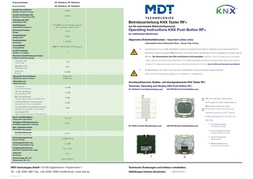
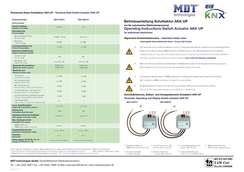
MDT Technologies AKK-03UP.02 User manual

Technical Manual Switch Actuator, FanCoil
MDT technologies GmbH • 51766 Engelskirchen • Papiermühle 1
2
1 Content
1 Content................................................................................................................................................. 2
2 Overview............................................................................................................................................... 5
2.1 Overview Devices .......................................................................................................................... 5
2.2 Exemplary circuit diagram ............................................................................................................ 5
2.3 Usage & Areas of Apllication ......................................................................................................... 6
2.4 Design & Usage.............................................................................................................................. 7
2.5 Setting at the ETS-Software........................................................................................................... 8
2.6 Starting Up..................................................................................................................................... 8
3 Communication objects........................................................................................................................ 9
3.1 Mode: Actuator ............................................................................................................................. 9
3.1.1 Overview and Usage............................................................................................................... 9
3.1.2 Default-Settings of the Communication Objects.................................................................. 12
3.2 Mode: FanCoil ............................................................................................................................. 13
3.2.1 Overview and Usage............................................................................................................. 13
3.2.2 Default settings of the communication objects ................................................................... 18
4 Configuration of the operating mode ................................................................................................ 20
4.1 General Settings .......................................................................................................................... 20
5 Reference ETS-Parameter - Actuator ................................................................................................. 21
5.1 Channel selection ........................................................................................................................ 21
5.2 Switching Actuator Mode............................................................................................................ 22
5.2.1 Relay operating mode .......................................................................................................... 22
5.2.2 Central function.................................................................................................................... 23
5.2.3 Behavior at locking/unlocking .............................................................................................. 23
5.2.4 Behavior at bus power down/bus power up........................................................................ 24
5.2.5 On/Off delay ......................................................................................................................... 25
5.2.6 State functions...................................................................................................................... 26
5.2.7 Priority/Forced control......................................................................................................... 27
5.2.8 Logic functions...................................................................................................................... 28
5.2.9 Scenes................................................................................................................................... 30
5.3 Staircase light .............................................................................................................................. 33
5.3.1 Relay operating mode .......................................................................................................... 33
5.3.2 Central function.................................................................................................................... 34
5.3.3 Behavior at locking/unlocking .............................................................................................. 34
5.3.4 Behavior at bus power down/bus power up........................................................................ 35
5.3.5 State functions...................................................................................................................... 36
5.3.6 Priority/Forced control......................................................................................................... 38

Technical Manual Switch Actuator, FanCoil
MDT technologies GmbH • 51766 Engelskirchen • Papiermühle 1
3
5.3.7 Scenes................................................................................................................................... 39
5.3.8 Staircase with variable time ................................................................................................. 42
5.3.9 Prewarning function............................................................................................................. 42
5.3.10 Manual switch off............................................................................................................... 44
5.3.11 Extend time of staircase light ............................................................................................. 44
5.3.12 Additional switching object................................................................................................ 45
5.4 Switch pulse................................................................................................................................. 46
5.4.1 Relay operating mode .......................................................................................................... 46
5.4.2 Pulse function....................................................................................................................... 47
5.4.3 Locking function ................................................................................................................... 48
6 Parameter - FanCoil............................................................................................................................ 49
6.1 General Functions........................................................................................................................ 49
6.1.1 FanCoil-System ..................................................................................................................... 49
6.1.2 General FanCoil settings....................................................................................................... 51
6.1.3 Blocking Functions................................................................................................................ 54
6.1.4 Activation of further submenus ........................................................................................... 55
6.2 Additional Ventilation ................................................................................................................. 56
6.2.1 Automatic additional ventilation.......................................................................................... 56
6.2.2 Manual additional ventilation .............................................................................................. 56
6.3 Automatic Mode.......................................................................................................................... 57
6.3.1 Automatic Mode –Control Value......................................................................................... 57
6.3.2 Automatic mode –Delta T.................................................................................................... 62
6.4 Direct Mode................................................................................................................................. 66
6.4.1 binary coded......................................................................................................................... 66
6.4.2 Step switch ........................................................................................................................... 66
6.4.3 - 1 Bit Up/Down.................................................................................................................... 66
6.4.4 - 1 Byte Value........................................................................................................................ 67
6.5 State............................................................................................................................................. 67
6.5.1 Status Fan at heating/cooling mode active.......................................................................... 68
6.5.2 Status maximum control value............................................................................................. 68
6.5.3 Status maximum Level –1 Byte............................................................................................ 69
6.5.4 State maximum Level 3/4 x 1 Bit.......................................................................................... 69
7 Index ................................................................................................................................................... 70
7.1 List of figures ............................................................................................................................... 70
7.2 List of tables................................................................................................................................. 72
8 Attachment......................................................................................................................................... 74
8.1 Statutory requirements............................................................................................................... 74
8.2 Routine disposal .......................................................................................................................... 74

Technical Manual Switch Actuator, FanCoil
MDT technologies GmbH • 51766 Engelskirchen • Papiermühle 1
4
8.3 Assemblage.................................................................................................................................. 74
8.4 Datasheet .................................................................................................................................... 74
Technical Manual Switch Actuator, FanCoil
MDT technologies GmbH • 51766 Engelskirchen • Papiermühle 1
5
2 Overview
2.1 Overview Devices
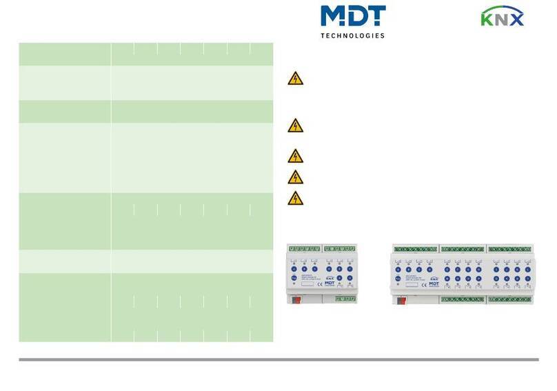
The manual refers to the following devices (Order number printed in bold letters):
AKK-03UP.02 Switch actuator 3-fold flush mounted, FanCoil
oFlush mounted, Nominal Voltage: 230VAC, Maximum Load: 10A
Switch Actuator - Mode: Switching and Staircase functions, Logic Function, Blocking
functions, central function, scene functions
FanCoil-Mode: Controlling 3 three phase Fans, 2 Blocking objects, Additional ventilation,
Automatic mode via control value or Delta T available, switching times individual adjustable
AKK-04FC.02 Switch actuator 4-fold, 2SU, FanCoil
oMDRC 2SU, Nominal Voltage: 230VAC, maximum Load: 16A
Switch Actuator - Mode: Switching and Staircase functions, Logic Function, Blocking
functions, central function, scene functions
FanCoil-Mode: Controlling four phase Fans, 2 Blocking objects, Additional ventilation,
Automatic mode via control value or Delta T available, switching times individual adjustable
2.2 Exemplary circuit diagram
Connecting as switch actuator:
Figure 1: Exemplary circuit diagram - Actuator

Technical Manual Switch Actuator, FanCoil
MDT technologies GmbH • 51766 Engelskirchen • Papiermühle 1
6

Technical Manual Switch Actuator, FanCoil
MDT technologies GmbH • 51766 Engelskirchen • Papiermühle 1
7
2.4 Design & Usage
The AKK-03UP.01 is designed for flush-mounting. Contacting the loads can be done by using the
connecting cables. Furthermore the actuator contains of the standard elements like programming
button and programming LED.
Figure 3: Overview hardware

Technical Manual Switch Actuator, FanCoil
MDT technologies GmbH • 51766 Engelskirchen • Papiermühle 1
8
2.5 Setting at the ETS-Software
Selection at the product database:
Manufacturer: MDT Technologies
Product family: Actuator
Product type: Switching, Staircase
Medium Type: Twisted Pair (TP)
Product name: AKK-03UP.01
Order number: AKK-03UP.01
2.6 Starting Up
After wiring the allocation of the physical address and the parameterization of every channel follow:
(1) Connect the interface with the bus, e.g. MDT USB interface
(2) set bus power up
(3) Press the programming button at the device(red programming LED lights)
(4) Loading of the physical address out of the ETS-Software by using the interface(red LED goes
out, as well this process was completed successful)
(5) Loading of the application, with requested parameterization
(6) If the device is enabled you can test the requested functions(also possible by using the ETS-
Software)

Technical Manual Switch Actuator 3-fold, FanCoil
MDT technologies GmbH • 51766 Engelskirchen • Papiermühle 1 • Tel.: +49-2263-880 • Fax: +49-2263-4588 • [email protected] • www.mdt.de
9
3 Communication objects
3.1 Mode: Actuator
3.1.1 Overview and Usage
No.
Name
Object function
Data type
Direction
Info
Usage
Tip
General Functions:
48
Central function
Switch on/off
DPT 1.001
receive
Actuator reacts to
Incoming-telegramm
Push buttons,
Visu...
for manual
control
Communication object is always
shown and enbales the central
on/off switching of all channels,
which have an enabled central
function.
50
Operating
Send Status
DPT 1.011
send
Actuator sends
Operating-Telgeram
cyclic
Diagnostic
Object is shown when the cyclic
Operating telegram is set to active.
Functions per channel:
0
Channel A
Switch on/off
DPT 1.001
receive
Actuator reacts to
Incoming-telegramm
Push buttons,
Visu...
for manual
control
Communication object is shown at
the operatig ode „sitch and
controls the channel On/Off, which
is normally connected to all control
keys.
(= Main function at switch)
1
Channel A
Staircase
DPT 1.001
receive
Actuator reacts to
Incoming-telegramm
Push buttons,
Visu...
for manual
control
Communication object is shown at
the operating mode „sitch and
controls the channel On/Off, which
is normally connected to all control
keys. The channel switches off again
after adjusted time is expired.
(= Main function at staircase)

Technical Manual Switch Actuator 3-fold, FanCoil
MDT technologies GmbH • 51766 Engelskirchen • Papiermühle 1 • Tel.: +49-2263-880 • Fax: +49-2263-4588 • [email protected] • www.mdt.de
10
1
Channel A
Switch pulse
DPT 1.001
receive
Actuator responds to
input telegram
Control buttons,
Visu ...
for manual
operation
Basic function of the function
switch pulse,
Communication object allows the
pulsed switching of the output.
3
Channel A
Block
DPT 1.003
receive
Actuator reacts to
Incoming-telegramm
Push buttons,
Visu...
for manual
control
Communication object is only
shown after activation of the
blocking object. Object blocks the
function of this channel.
(= Additional function)
4
Channel A
Scene
DPT 18.001
receive
Actuator reacts to
Incoming-telegramm
Push buttons,
Visu...
for manual
control
Communication onject appears only
after activating scenes. For calling
of saved scenes, which are saved in
the actuator.
(= Additional function)
5
Channel A
Status
DPT 1.001
sending
Actuator sends
current state
For diplay on
Visu, Tableau,
and Display
Connection to
Push button
ojet „Value for
toggle
Communication object operates as
status indication and can be used
for isualizatio…
Must be connected to the object
alue for toggle of the cotrollig
push button for sending its current
state to the push button.
6
Channel A
Logic 1
DPT 1.002
receive
Actuator reacts to
Incoming-telegramm
external
switching, state
object of other
devices
Channel switches only On, if the
logic function of activated objects
and switching onbject (Nr. 85) is
true.
Only available for switching output.

Technical Manual Switch Actuator 3-fold, FanCoil
MDT technologies GmbH • 51766 Engelskirchen • Papiermühle 1 • Tel.: +49-2263-880 • Fax: +49-2263-4588 • [email protected] • www.mdt.de
11
7
Channel A
Logic 2
DPT 1.002
receive
Actuator reacts to
Incoming-telegramm
external
switching, state
object of other
devices
Channel switches only On, if the
logic function of activated objects
and switching onbject (Nr. 85) is
true.
Only available for switching output.
+11 next channel
Table 1: Overview communication objects - Switch actuator

Technical Manual Switch Actuator 3-fold, FanCoil
MDT technologies GmbH • 51766 Engelskirchen • Papiermühle 1
12
3.1.2 Default-Settings of the Communication Objects
The following table shows the default settings of the communication objects:
Default settings
No.
Name
Object Function
Length
Priority
C
R
W
T
U
0
Channel A
switch on/off
1 Bit
Low
X
X
1
Channel A
Staircase
1 Bit
Low
X
X
1
Channel A
Switch pulse
1 Bit
Low
X
X
2
Channel A
Block
1Bit
Low
X
X
4
Channel A
Scene
1Byte
Low
X
X
5
Channel A
Status
1Bit
Low
X
X
X
6
Channel A
Logic 1
1Bit
Low
X
X
7
Channel A
Logic 2
1Bit
Low
X
X
+11
next channel
Table 2: Communication objects - Default settings - Switch actuator
You can see the default values for the communication objects from the upper chart. According to
requirements the priority of the particular communication objects as well as the flags can be
adjusted by the user. The flags allocates the function of the objects in the programming thereby
stands C for communication, R for Read, W for write, T for transmit and U for update.

Technical Manual Switch Actuator 3-fold, FanCoil
MDT technologies GmbH • 51766 Engelskirchen • Papiermühle 1 • Tel.: +49-2263-880 • Fax: +49-2263-4588 • [email protected] • www.mdt.de
13
3.2 Mode: FanCoil
3.2.1 Overview and Usage
No.
Name
Object function
Data type
Direction
Info
Usage
Tip
General functions:
46
Operating
Send Status
DPT 1.011
send
Actuator sends
Operating-Telgeram
cyclic
Diagnostic
Object is shown when the cyclic
Operating telegram is set to active.
47
Day/Night
Switching
DPT 1.001
receive
Actuator reacts to
Incoming-telegram
Time Switch,
Control key,
Visu…
Object is shown when Day/Night is
active. The usage of the day/night
object allows limiting the maximum
FanCoil Level at night.
General FanCoil objects:
1
Switching
Auto/Manual
1 = Automatic/ 0 =
Manual
DPT 1.001
send/
receicve
Actuator reacts to
Incoming telegram
and sends state at
automatic switchover
Central
Operation Unit,
Visu, Operating
keys
Object is always shown and is used
for switching between automatic
and manual mode and status for
switchover.
25
Blocking object 1
Block
DPT 1.003
receive
Actuator reacts to
Incoming-telegram
Central
Operation Unit,
Visu, Operating
keys
Communication object is shown
when blocking 1 is active in the
parameters and can be sued for
blocking the actuator.
26
Blocking object 2
Block
DPT 1.003
receive
Actuator reacts to
Incoming-telegram
Central
Operation Unit,
Visu, Operating
keys
Communication object is shown
when blocking 2 is active in the
parameters and can be sued for
blocking the actuator.

Technical Manual Switch Actuator 3-fold, FanCoil
MDT technologies GmbH • 51766 Engelskirchen • Papiermühle 1 • Tel.: +49-2263-880 • Fax: +49-2263-4588 • [email protected] • www.mdt.de
14
Objects for additional ventilation:
0
Additional
Ventilation
Enable additional
ventilation
DPT 1.001
receive
Actuator reacts to
incoming telegram
Central
Operation Unit,
Visu, Operating
keys, Time switch
Object is shown when manual
additional ventilation is activated
and activates the additional
ventilation for the adjusted time.
Objects for Automatic mode:
2
Automatic mode
Control value heating
DPT 5.001
receive
Actuator reacts to
incoming telegram
Regulatio…
Communication object is shown
when a heating systems and the
autoati ode Cotrol alue is
active; Receiving the current control
value.
2
Automatic mode
Control value
heating/cooling
DPT 5.001
receive
Actuator reacts to
incoming telegram
Regulatio…
Communication object is shown at
2-Pipe systems and the automatic
ode Cotrol alue is atie;
Receiving the current control value.
3
Automatic mode
Control value cooling
DPT 5.001
receive
Actuator reacts to
incoming telegram
Regulatio…
Communication object is shown
when a cooling systems and the
automati ode Cotrol alue is
active; Receiving the current control
value.
4
Automatic mode
Control value failure
DPT 1.001
send
Actuator sends state
Visualization,
Displa…
Communication object is shown at
autoati ode Cotrol alue
and can sends a control value
failure if this option is active.
5
Automatic mode
Heating/Cooling
switchover
DPT 1.100
send/
receive
Actuator reacts to
incoming telegram
and sends state
Push Button,
Regulation,
Visualizatio…
Object is shown at combined
heating and cooling systems and is
used, according to the
parameterization, for switching or
visualization.

Technical Manual Switch Actuator 3-fold, FanCoil
MDT technologies GmbH • 51766 Engelskirchen • Papiermühle 1 • Tel.: +49-2263-880 • Fax: +49-2263-4588 • [email protected] • www.mdt.de
15
6
Automatic mode
Switch heating valve
DPT 1.001
send
Actuator sends
switching telegram
separate
switching
channel for
switching the
heating valve of
the FanCoil-
system
Object is always shown when
heating mode is active.
7
Automatic mode
Switch cooling valve
DPT 1.001
send
Actuator sends
switching telegram
separate
switching
channel for
switching the
cooling valve of
the FanCoil-
system
Object is always shown when
cooling mode is active.
8
Automatic mode
Manual setpoint offset
DPT 1.007
receive
Actuator reacts to
incoming telegram
Central operation
unit, Visu, Push
Butto…
Object can be activated at
autoati ode Delta T
27
Automatic mode
Temperature value
DPT 9.001
receive
Actuator reacts to
incoming telegram
Temperature-
sensor
Object is always shown at
autoati ode Delta T ad is
used for receiving the current
temperature.
28
Automatic mode
Setoint temperature
DPT 9.001
receive
Actuator reacts to
incoming telegram
Central operation
unit, Visu, Push
Butto…
Object is always shown at
autoati ode Delta T ad is
used for receiving a new setpoint.
29
Automatic mode
Setpoint offset
DPT 9.002
receive
Actuator reacts to
incoming telegram
Central operation
unit, Visu, Push
Butto…
Object can be activated at
autoati ode Delta T ad is
used for receiving a setpoint offset.
30
Automatic mode
Current setpoint
temperature
DPT 9.001
send
Actuator sends state
Visualizatio…
Object is always shown at
autoati ode Delta T ad is
used for visualization the current
setpoint.

Technical Manual Switch Actuator 3-fold, FanCoil
MDT technologies GmbH • 51766 Engelskirchen • Papiermühle 1 • Tel.: +49-2263-880 • Fax: +49-2263-4588 • [email protected] • www.mdt.de
16
Objects for Direct Mode:
9
Direct Mode
Step 0
DPT 1.001
receive
Actuator reacts to
incoming telegram
Central operation
unit, Visu, Push
Butto…
Object is shown when direct mode
via step switch is activated and
switches the FanCoil off by
reeiig a .
9
Direct Mode
Bit 0
DPT 1.001
receive
Actuator reacts to
incoming telegram
Central operation
unit, Visu, Push
Butto…
Object is shown when direct mode
binary coded is activated and
switches Bit 0 of the binary value.
9
Direct Mode
Up/Down
DPT 1.007
receive
Actuator reacts to
incoming telegram
Central operation
unit, Visu, Push
Butto…
Object is shown when direct mode
via 1 Bit Up/Down is activated and
switches the FanCoil one step down
by receiig a ad oe step up
reeiig a .
10
Direct Mode
Step 1
DPT 1.001
receive
Actuator reacts to
incoming telegram
Central operation
unit, Visu, Push
Butto…
Object is shown when direct mode
via step switch is activated and
switches the FanCoil into step 1 by
reeiig a .
10
Direct Mode
Bit 1
DPT 1.001
receive
Actuator reacts to
incoming telegram
Central operation
unit, Visu, Push
Butto…
Object is shown when direct mode
binary coded is activated and
switches Bit 1 of the binary value.
11
Direct Mode
Step 2
DPT 1.001
receive
Actuator reacts to
incoming telegram
Central operation
unit, Visu, Push
Butto…
Object is shown when direct mode
via step switch is activated and
switches the FanCoil into step 2 by
reeiig a .
12
Direct Mode
Step 3
DPT 1.001
receive
Actuator reacts to
incoming telegram
Central operation
unit, Visu, Push
Butto…
Object is shown when direct mode
via step switch is activated and
switches the FanCoil into step 3 by
reeiig a .

Technical Manual Switch Actuator 3-fold, FanCoil
MDT technologies GmbH • 51766 Engelskirchen • Papiermühle 1 • Tel.: +49-2263-880 • Fax: +49-2263-4588 • [email protected] • www.mdt.de
17
Objects for state:
13
Status Input
(Cascading)
External heating request
DPT 1.001
receive
Actuator receives
state
State FanCoil
Actuator
Object is shown when cascading is
active for this state.
14
Status Output
External heating request
DPT 1.001
send
Actuator sends state
Visu, Actuator,
Regulatio…
Object is shown when this state is
active.
15
Status Input
(Cascading)
External cooling request
DPT 1.001
receive
Actuator receives
state
State FanCoil
Actuator
Object is shown when cascading is
active for this state.
16
Status Output
External cooling request
DPT 1.001
send
Actuator sends state
Visu, Actuator,
Regulatio…
Object is shown when this state is
active.
17
Status Input
(Cascading)
Maximum control value
for heating
DPT 5.001
receive
Actuator receives
state
State FanCoil
Actuator
Object is shown when cascading is
active for this state.
18
Status Output
Maximum control value
for heating
DPT 5.001
send
Actuator sends state
Visu, Actuator,
Regulatio…
Object is shown when this state is
active.
19
Status Input
(Cascading)
Maximum control value
for cooling
DPT 5.001
receive
Actuator receives
state
State FanCoil
Actuator
Object is shown when cascading is
active for this state.
20
Status Output
Maximum control value
for cooling
DPT 5.001
send
Actuator sends state
Visu, Actuator,
Regulatio…
Object is shown when this state is
active.
21
Status Input
(Cascading)
Maximum fan level
heating
DPT 5.005
receive
Actuator receives
state
State FanCoil
Actuator
Object is shown when cascading is
active for this state.
22
Status Output
Maximum fan level
heating
DPT 5.005
send
Actuator sends state
Visu, Actuator,
Regulatio…
Object is shown when this state is
active.
23
Status Input
(Cascading)
Maximum fan level
cooling
DPT 5.005
receive
Actuator receives
state
State FanCoil
Actuator
Object is shown when cascading is
active for this state.
24
Status Output
Maximum fan level
cooling
DPT 5.005
send
Actuator sends state
Visu, Actuator,
Regulatio…
Object is shown when this state is
active.
Table 3: Overview communication objects - FanCoil

Technical Manual Switch Actuator 3-fold, FanCoil
MDT technologies GmbH • 51766 Engelskirchen • Papiermühle 1
18
3.2.2 Default settings of the communication objects
The following table shows the default settings of the communication objects:
Default settings
No.
Name
Object Function
Length
Priority
C
R
W
T
U
0
Additional
ventilation
Enable additional
ventilation
1 Bit
Low
X
X
1
Switching
Auto/Manual
1 = Automatic/ 0 =
Manual
1 Bit
Low
X
X
X
X
X
2
Automatic mode
Control value heating
1 Byte
Low
X
X
2
Automatic mode
Control value
heating/cooling
1 Byte
Low
X
X
3
Automatic mode
Control value cooling
1 Byte
Low
X
X
4
Automatic mode
Control value failure
1 Bit
Low
X
X
X
5
Automatic mode
Heating/Cooling
switchover
1 Bit
Low
X
X
X
X
X
6
Automatic mode
Switch heating valve
1 Bit
Low
X
X
X
7
Automatic mode
Switch cooling valve
1 Bit
Low
X
X
X
8
Automatic mode
Manual setpoint offset
1 Bit
Low
X
X
9
Direktbetrieb
Step 0
1 Bit
Low
X
X
9
Direktbetrieb
Bit 0
1 Bit
Low
X
X
9
Direktbetrieb
Up/Down
1 Bit
Low
X
X
10
Direktbetrieb
Step 1
1 Bit
Low
X
X
10
Direktbetrieb
Bit 1
1 Bit
Low
X
X
11
Direktbetrieb
Step 2
1 Bit
Low
X
X
12
Direktbetrieb
Step 3
1 Bit
Low
X
X
13
Status Input
(Cascading)
External heating
request
1 Bit
Low
X
X
14
Status Output
External heating
request
1 Bit
Low
X
X
X
15
Status Input
(Cascading)
External cooling request
1 Bit
Low
X
X
16
Status Output
External cooling request
1 Bit
Low
X
X
X
17
Status Input
(Cascading)
Maximum control value
for heating
1 Byte
Low
X
X
18
Status Output
Maximum control value
for heating
1 Byte
Low
X
X
X
19
Status Input
(Cascading)
Maximum control value
for cooling
1 Byte
Low
X
X
20
Status Output
Maximum control value
for cooling
1 Byte
Low
X
X
X
21
Status Input
(Cascading)
Maximum fan level
heating
1 Byte
Low
X
X
22
Status Output
Maximum fan level
heating
1 Byte
Low
X
X
X
23
Status Input
(Cascading)
Maximum fan level
cooling
1 Byte
Low
X
X

Technical Manual Switch Actuator 3-fold, FanCoil
MDT technologies GmbH • 51766 Engelskirchen • Papiermühle 1
19
24
Status Output
Maximum fan level
cooling
1 Byte
Low
X
X
X
25
Blocking Object 1
Block
1 Bit
Low
X
X
26
Blocking Object 2
Block
1 Bit
Low
X
X
27
Automatic mode
Temperature value
2 Byte
Low
X
X
28
Automatic mode
Setoint temperature
2 Byte
Low
X
X
29
Automatic mode
Setpoint offset
2 Byte
Low
X
X
30
Automatic mode
Current setpoint
temperature
2 Byte
Low
X
X
X
46
Operating
Send Status
1 Bit
Low
X
X
47
Day/Night
Switching
1 Bit
Low
X
X
Table 4: Communication objects - Default settings –FanCoil
You can see the default values for the communication objects from the upper chart. According to
requirements the priority of the particular communication objects as well as the flags can be
adjusted by the user. The flags allocates the function of the objects in the programming thereby
stands C for communication, R for Read, W for write, T for transmit and U for update.

Technical Manual Switch Actuator 3-fold, FanCoil
MDT technologies GmbH • 51766 Engelskirchen • Papiermühle 1
20
4 Configuration of the operating mode
The operating mode of the device can be chosen at the general settings of the device:
Figure 4: Selection of the operating mode
According to the adjusted operating mode, the parameter and communication objects are loaded.
If the operatig ode Atuator is hose, the settigs ad ojets are aailale as desried i 5
Reference ETS-Parameter .
If the operatig ode Atuator is hose, the settings and objects are available as described in6
Parameter - FanCoil.
4.1 General Settings
The following table shows the general settings for the AKK-03UP.01:
ETS-text
Dynamic range
[default value]
comment
Startup timeout
0-120s
[5s]
Time between a reset and the
functional start of the device
Cli „Operatig telegra
not used
2 min –24h
Adjustment if a
„Operatig telegra is sed
cyclic on the bus.
Day/Night object
not used
use, no read
use, read after reset
Adjustment if a Day/Night
object is used and whether it
should be read after a reset or
not.
Only used in FanCoil Mode.
Polarity of day/night object
Day = 1 / Night = 0
Day= 0 / Night = 1
Adjustment of the polarity of
the day/night object.
Table 5: General settings
The following table shows the communication objects:
Number
Name
Length
Usage
46
Operating
1 Bit
Sending a cyclic operating-telegram
47
Day/Night
1 Bit
Switching between day/night mode
Table 6: Communication objects - General
This manual suits for next models
1
Table of contents
Other MDT Technologies Controllers manuals

MDT Technologies
MDT Technologies BE-GT2TW.01 User manual

MDT Technologies
MDT Technologies AKS Series User manual

MDT Technologies
MDT Technologies SCN-RT1UP.01 User manual

MDT Technologies
MDT Technologies AKU-0816.01 User manual

MDT Technologies
MDT Technologies AMI-0416.03 User manual

MDT Technologies
MDT Technologies AKH-0400.01 User manual

MDT Technologies
MDT Technologies AKH-0400.01 User manual

MDT Technologies
MDT Technologies JAL-0206.01 User manual

MDT Technologies
MDT Technologies JAL-01UP.02 User manual

MDT Technologies
MDT Technologies AKK UP Series User manual