Mec ATLAS-650 Series User manual

Mainland Energy Conversion Ltd.
Tel: +852 2366 9610
E-mail: mec@mec-mainland.com
www.mec-powersolutions.com
Instruction Manual
Battery Chargers
ATLAS-650 Series:
Safety Rules and General Warnings
•Persons, who are not able to use the charger in a safe way, because of their physical, sensory or mental incompetence, or because of their
lack of experience, should not use without the control or instruction from a skilled or qualified person.
•The charger runs with 100-240 Volts alternating current, which is not suitable for children – Danger of Life. And beware of risk of electric shock
at all times.
•Avoid flammable gases, solvents or vapours all the time. Prevent open flame or sparks while charging in progress. Explosion RISK!
•Ensure sufficient air ventilation and prevent open flame or sparks while charging in progress.
•The charger is exclusively designed for charging rechargeable batteries and must not be used for other purposes. Corresponding model should
be selected for particular lithium-based or lead-based batteries.
•You should take into consideration of the charging instructions issued by the battery manufacturer before charging. Check also if the charge
profile fits your battery and application.
•DO NOT OPEN or DISMANTLE the charger. Repair work must only be processed by authorized technical staff.
•If the mains connection of the charger is damaged, it must be replaced with an original wire which is available at MEC or authorized dealers.
•NEVER place the charger on top of the battery while charging in progress.
•The charger should be protected against direct solar radiation or temperatures over 40°C.
•In case of obvious damage or malfunctioning, disconnect the charger from the mains supply and protect against unintended reconnection.
•The DC cable must not be cut, shortened or extended under any circumstances.
Special Features
•IP65 Passive cooling; extruded aluminium-alloy housing
•Microprocessor-based 4-Step charging technology with soft start and automatic re-start of the charge cycle
•5 Selectable battery types (GEL, AGM, WET, Calcium, +PS-Mode) and built-in battery temperature sensor for models targeting lead-based
batteries
•LED indicators showing corresponding charge status and errors
•Protection against short circuit, reverse polarity, over temperature or overload
•Battery recovery function for attempting to revive a deeply discharged or "dead" battery with recurring series of voltage/current pulses
Product Configuration
Models Targeting Lithium-based Batteries
1. Protective Vent
2. Red Error LED
3. Green Full LED
4. Yellow Charge LED
5. Green Mains LED
6. IR-Interface LEDs
7. Red DC Positive Cable
8. Black DC Negative Cable
9. Blue Load Enable (model dependent)
10. Ignition Lock (model dependent)
11. Display Terminal (model dependent)
12. AC Cable
IP65 water resistant, microprocessor-based. With one (1) or
multiple, selectable charge profiles, customized parameters.
CAN-bus / Ignition-Lock (optional).
ATLAS-650

Instruction Manual ATLAS-650 Series
Version: May 2020 - 2 -Mainland Energy Conversion Ltd.
Tel: +852 2366 9610
E-mail: mec@mec-mainland.com
www.mec-powersolutions.com
Models Targeting Lead-based Batteries
Preparation –Before Charging
General Checking
•Check thoroughly the charger itself including all the cables show no damages
•Take into consideration the charging instruction issued by the battery manufacturer
Charging Cable – Polarity Checking
WARNING: Check the polarity before mounting onto a plug:
•Red cable = Plus (+)
•Black cable = Minus (-)
DC Mains Supply Checking
•Make sure the DC cable must not be cut, shortened or extended under any circumstances
•Make sure the mains supply complies with the technical specification requirements of the charger
Before Connecting the Charger to the Battery
•<For models targeting lead-acid batteries> First connect charger to the mains to select the appropriate loader, then disconnect from the
mains and connect the temperature sensor to the battery (the assembly depends on the battery manufacturer)
•<For all models> Make sure the charger is switched off and disconnected from the mains supply
•Then connect the terminals of the charger to the battery
•Finally connect the power cable of the charger to the mains supply, and switch on the charger
•The immobilizer core is switched to 0V when the charging process starts
For Models Targeting Lead-based Batteries
•Select the desired charge profile:
With proper connection, the LED of the currently active charge profile lights up continuously. To change the charge profile, press and hold the
"Press Button" for 5 seconds, the LED of the active profile will then change to slow flashing. Now you can switch between the different charge
profiles by briefly pressing the "Press Button". When the desired profile is selected, confirm the selection by pressing the "Press Button” again
for 5 seconds, the LED of the selected charge profile changes to steady lighting.
•Select the Power Supply Mode:
Follow the steps above to select a charge profile; the Power Supply Mode is signaled by the lighting up of all the 4 charge profile LEDs.
•The latest selected charge profile will be kept unless you change it
Charging the Battery
The charging process starts automatically and runs through the following stages:
Getting Ready: Auto Wake-up
Yellow Charge LED (4) and Green Full LED (3) are blinking alternately. During this pre-charge phase, the charger sends out series of controlled
current pulses to reactivate the BMS (if any) and bring in a voltage to the battery for getting ready for the charging process. If no battery or defected
battery pack is connected, the Red Error LED blinks. In this case, switch off the charger and check the battery pack.
1. Selection Switch
2. Program LED
3. Green Full LED
4. Yellow Charge LED
5. Green Mains LED
6. Red Error LED
7. IR-Interface LEDs
8. DC Cable (Red + ; Black - )
9. Temperature Sensor
10. Ignition Lock (model dependent)
11. Display Terminal (model dependent)
12. AC Cable

Instruction Manual ATLAS-650 Series
Version: May 2020 - 3 -Mainland Energy Conversion Ltd.
Tel: +852 2366 9610
E-mail: mec@mec-mainland.com
www.mec-powersolutions.com
Phase 1: Soft Start
Yellow Charge LED (4) keeps on lighting. The charger regulates the initial charging current to better prolong the battery life.
Phase 2: Constant Current Charging
Yellow Charge LED (4) blinks slowly. The battery is being charged to 80% of its capacity at this stage.
Phase 3: Constant Voltage Charging
Yellow Charge LED (4) blinks quickly. The battery is being charged to its maximum capacity. When the Green Full LED (3) turns on, the charger can
now be disconnected from the battery.
Phase 4: Float Charging (for lead-based batteries only) or Auto Restart
Green Full LED (3) keeps on lighting indicate the battery has reached its full capacity. If the battery keeps connecting to the charger, auto restart of
the charging cycle will take place after 7 days or when the battery voltage has dropped to under 3.6V/cell (Li-ion Battery) or 3.2V/cell (LiFePO4
Battery).
Disconnect the Charger from the Battery:
1. First, disconnect the charger from the mains supply
2. Then, disconnect the charger from the battery
After disconnecting the charger from the mains, please wait at least 5 seconds to reactivate the charger if in need – otherwise damages may be
resulted.
Charging Advice and Battery Care
Charging Advice:
•If the charger must be disconnected from the battery during the charging process, please FIRST disconnect the charger from the mains supply.
The continuation of the charging process is equal to a new charging cycle; all relevant points of the Operating Instructions have to be considered.
•To lengthen the lifetime of the battery, please do not stop the charging process before the battery is fully charged. The charger will automatically
stop when the charging process is completed.
Battery Care:
•Never expose the battery to high temperatures, as this causes permanent battery capacity loss.
•Never deep-discharge or overcharge the battery, cells can be damaged irreversibly.
•If possible, always disconnect the battery from the load when being stored over long period of time.
•Store battery in a dry and cool place at about 40-60% of its rated capacity.
General Errors Description
Solutions
No LED lighting or blinking after connecting to the mains
•Check if the charger is connected to mains supply properly
•Check if there are any problems with the mains supply
Red Mains-LED is on, charger is connected to the battery,
but the charging process seems not working
•Check the connection to battery
•Check if the battery is damaged or has been deeply discharged
Error-LED blinking (N x blinking / 2 secs pause)
•Please refer to the table below for LED Blinking Signals
LED Blinking Signal (continuous looping)
Error Description
1 x
Battery damaged
2 x
Battery voltage is too high or wrong battery connection
5 x
Charger temperature is too high during the charging process
8 x
Short-circuited
Advice for Disposal
It is prohibited to dispose the charger with household or residual waste removal (WEEE-Richtlinie 2012/19/EU und
EAG-VO). The charger must be disposed at designated disposal points. For the protection of our environment, please
check at your communal adminstrative agency of your nearest disposal point.
The charger conforms to the RoHS-directive EU 2015/863, for the restriction of the use of certain
hazardous substances in electrical and electronic equipment.
Errors and Troubleshooting

Instruction Manual ATLAS-650 Series
Version: May 2020 - 4 -Mainland Energy Conversion Ltd.
Tel: +852 2366 9610
E-mail: mec@mec-mainland.com
www.mec-powersolutions.com
Disclaimer of Warranty
The warranty period (see our General Terms and Conditions) starts with the charger being dispatched by the manufacturer. MEC-Energietechnik
GmbH accepts liability by guaranteeing to working hours and spare parts only.
For damages caused by non-observance of the operating instructions, inappropriate start up or handling as well as dismantling, reconstructions or
modifications of the charger, the warranty claim expires and MEC-Energietechnik GmbH assumes no liability for consequential damages to any
properties or persons in connection with or arising from the purchase and use of the charger.
We reserves the rights to configure the charger as per actual needs and the manual may not reflect the most updated conditions of the product at all
times. Please contact us should you need any technological support.
Technical Specifications
DC Ausgang | DC Output
LiFePO4 Batteries
3.2V/cell (nom.)
Li-ion Batteries
3.6V/cell (nom.)
Lead-based Batteries
Ladespannung max.
Charge Voltage
max. (+/-1%)
8S
12S
14S
16S
7S
10S
14S
24V
36V
48V
25.6V
38.4V
44.8V
51.2V
25.2V
36.0V
50.4V
Ladestrom max.
Charge Current
max. (+/-1%)
23A
15A
13A
11A
22A
15A
11A
22A
15A
11A
Wirkungsgrad max. | Efficiency max.
>92% @ 230V
Ausgangsleistung, nom. | Output Power, nom.
650W
Restwelligkeit | Ripple
<1%
Rückstrom | Back Current
<1mA
Ladekabel | Charge Cable
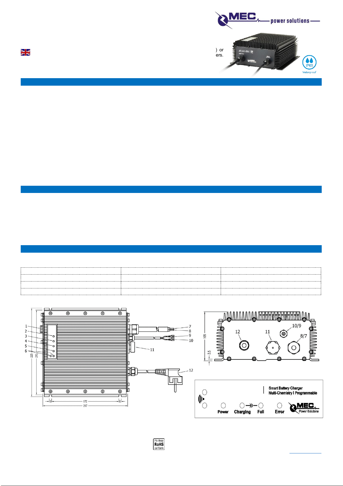
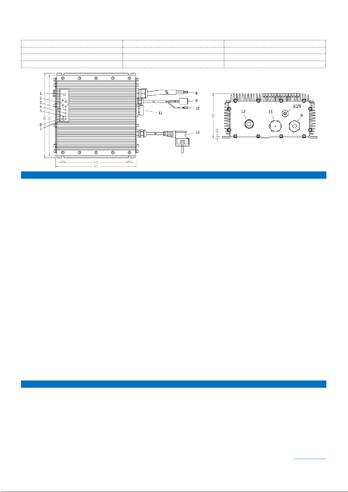
1.2m offene Kabelenden | 1.2m open cable ends
AC Eingang | AC Input
Eingangsspannung | Input Voltage
100...240VAC / 50...60Hz
Eingangsleistung max. | Input Power max.
700VAC [3A @ 240VAC]
Netzkabel & Stecker | Power Cord & Plug
1.2m, Länderspezifisch | Country Specific
Gehäuse | Enclosure
Werkstoff | Material
AL-Strangpreßprofil, anodisierte Oberfläche | Extruded AL-Profile, anodized surface
Abmessungen / Gewicht | Dimension / Weight
232.4 x 200 x 86.6 mm / ca. 4.0kg
LED-Anzeigen | LED-Indicators
Netz-, Error-, Laden-, Batt.-Voll Anzeige
Mains-, Error-, Charging-, Batt.-Full Indicator
Schutzklasse | Protection Class
1
IP Klasse | IP Code
IP65
Einsatztemperaturbereich | Operating Temp.
-30°C to +40°C
Kühlung | Cooling
Passive Kühlung | Passive Cooling
Besonderheiten | SpecialFeatures
4-Stufen Ladecharakteristik**
4-Step Charge Characteristics**
Abschaltung bei "Batterie-Voll" (Ladestromerkennung)
Charge Cut-off at "Batterry-Full" (Current Detection)
Ladefreigabe (opt.) | Charge Enable (opt.)***
Kabel f. Ladefreigabe / Ladesperre | Cable f. Charge Enable / Charge Disable
Wegfahrsperre | Ignition-Lock Function***
2-Adriges Kabel -> (Relaiskontakt) | 2-Core Cable -> (Dry-contact)
Ladeparameter | Charge Parameter
Ladeprofilanpassung über IR-Schnittstelle | Charge Profile Configurable via IR-Port
Automat. Batterie Weckfunktion
Automat. Battery Wake-up
Nach dem Einschalten weckt der Lader das BMS durch definierte Spannungspulse
The charger, after "Power-on", activates the BMS with pre-defined voltage pulses
Geräteschutz | Device Protection
Ü bertemperatur-, Kurzschluss-, Überlastschutz
Over temperature-, Short Circuit-, Overload Protection
Zertifizierungen | Certification
CE
Spezifikationen der Akkuhersteller sind vorrangig zu beachten! | Specifications of the battery manufacturer take priority!
** Abweichende Ladeprofile auf Anfrage | Different charge profiles on request.
*** Optionale Varianten auf Anfrage | Optional features on request.
Subject to technical modifications. We assume no liability for misprints.
Other Mec Batteries Charger manuals

Mec
Mec Atlas-300IM User manual

Mec
Mec JOE-100 Series User manual

Mec
Mec TRITASK-300F Series User manual

Mec
Mec AV4m User manual

Mec
Mec TriTask-150s User manual

Mec
Mec JOE-100IM User manual

Mec
Mec TriTask-40 Series User manual

Mec
Mec NOVA-2000F Series User manual

Mec
Mec NOVA-100 Series User manual

Mec
Mec TriTask-300 Series User manual

Mec
Mec MCC-40 User manual

Mec
Mec AdapTask-150 Series User manual

Mec
Mec ProTask-360 Series User manual

Mec
Mec NOVA-750F Series User manual

Mec
Mec NOVA-1500F Series User manual

Mec
Mec MCC-40 User manual

Mec
Mec Atlas-200IM User manual

Mec
Mec ATLAS-500 Series User manual

Mec
Mec NOVA-1000F Series User manual

Mec
Mec 161-06402-430 User manual