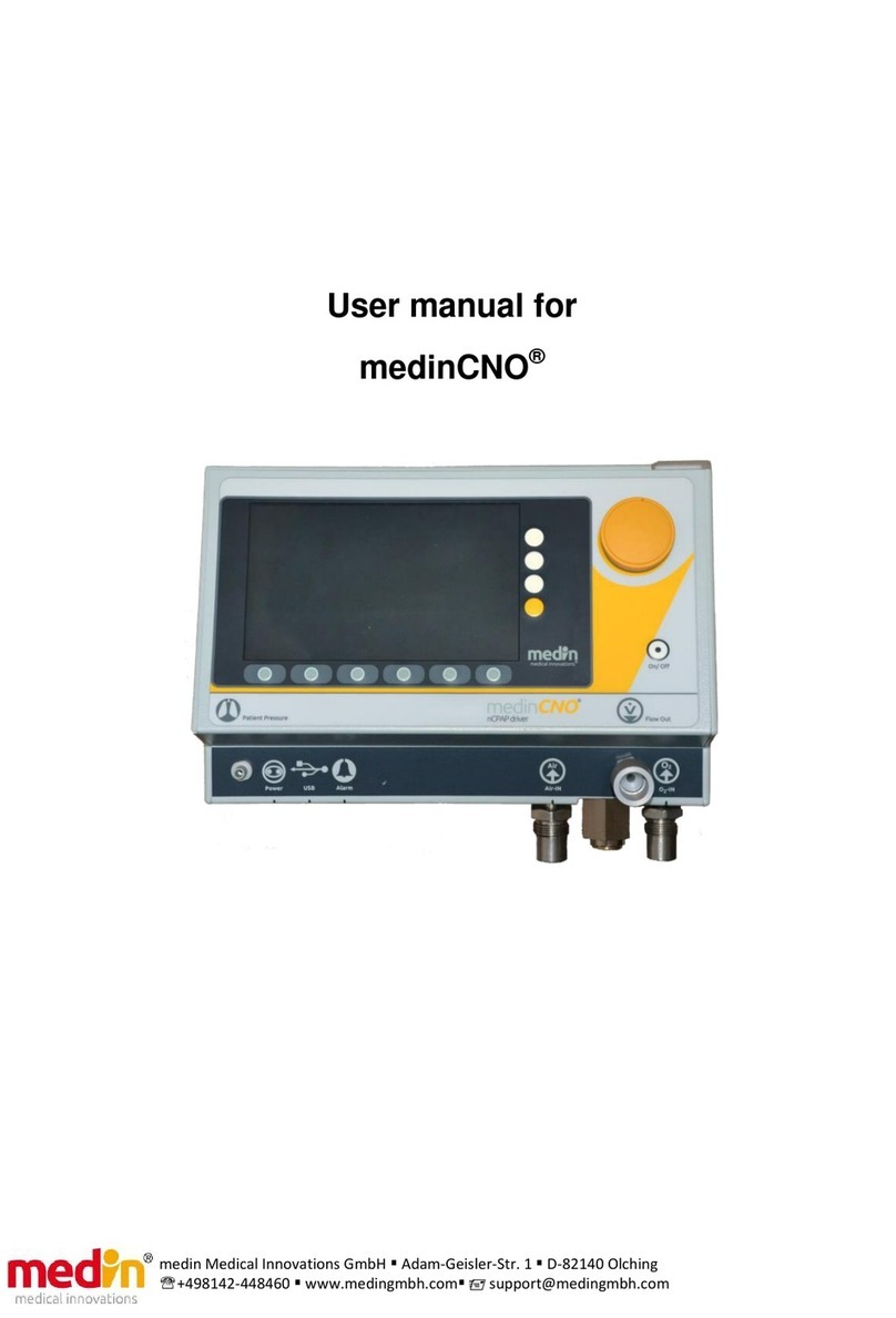
Medin medinCNO User manual

User manual for
medinCNO®

+49 8142 448 460
info@medin
-medical.com
www.medin
-medical.com
medin Medical Innovations GmbH
Adam
-Geisler-Str. 1
D-82140 Olching
OP_medinCNO EN
Rev 1
2 Stand 06.03.2019
2von 68
The medinCNO®contains batteries and electrical components. Consequently it cannot be
disposed of in domestic waste but must be collected separately and recycled in accordance
with local regulations. (WEEE)
0483
Classification (according to COUNCIL DIRECTIVE 93/42/EEC Annex IX): IIb
medin Medical Innovations GmbH
Adam-Geisler-Str. 1 – 82140 Olching – Germany
+49 8142-44846-0 – www.medin-medical.com – info@medin-medical.com
Made in Germany
OP_cno Rev 12 Correct as of: 06.03.2019

+49 8142 448 460
info@medin
-medical.com
www.medin
-medical.com
medin Medical Innovations GmbH
Adam
-Geisler-Str. 1
D-82140 Olching
OP_medinCNO EN
Rev 1
2 Stand 06.03.2019
3von 68
Table of Contents
Table of Contents ..............................................................................................................................................3
1Introduction ..........................................................................................................................................5
1.1 About the instructions for use.........................................................................................................5
1.2 General liability conditions..............................................................................................................5
2Description of the Device and Conditions for Use .................................................................................6
2.1 Intended purpose............................................................................................................................6
2.2 Operating staff ................................................................................................................................6
2.3 Alternative respiration systems.......................................................................................................6
2.4 Combination with other devices and ancillary equipment ..............................................................6
2.5 Technical description of function ....................................................................................................7
2.5.1 Principles of function ..........................................................................................................7
2.5.2 Technical data .....................................................................................................................7
2.5.3 Overview of the general technical description ....................................................................8
3Installation of the medinCNO®– Conditions ........................................................................................10
3.1 Mounting ......................................................................................................................................10
3.2 Power supply................................................................................................................................. 11
3.2.1 Mains operation................................................................................................................11
3.2.2 Battery operation.............................................................................................................. 11
3.2.3 Power supply unit .............................................................................................................12
3.3 Gas feed ........................................................................................................................................ 13
3.4 External alarm interface and data interfaces................................................................................. 14
3.4.1 External alarm...................................................................................................................14
3.4.2 USB data interface ............................................................................................................15
3.4.3 RS232 interface.................................................................................................................16
3.4.4 Output data (live and trend data) ..................................................................................... 17
3.5 Environmental conditions (operation / transport / storage) ......................................................... 20
4First Use ..............................................................................................................................................23
4.1 CPAP system components ............................................................................................................. 23
4.2 Connecting the medinCNO®and setting up the CPAP system........................................................ 24
4.3 Starting up the system .................................................................................................................. 26
5Operation ............................................................................................................................................28
5.1 Operator console .......................................................................................................................... 29
5.2 Display screen ............................................................................................................................... 30
5.3 Basic CPAP settings ....................................................................................................................... 31
5.4 Push ..............................................................................................................................................32
5.5 O2flush .........................................................................................................................................34
5.6 Backup function ............................................................................................................................ 34
5.7 CPAP mode.................................................................................................................................... 35
5.8 Apnoea CPAP mode ...................................................................................................................... 36
5.9 SNIPPV mode ................................................................................................................................ 38
5.10 Oscillation mode ..................................................................................................................... 41
5.11 Switching between modes ......................................................................................................43
5.12 Alarm settings ......................................................................................................................... 43
5.13 Trend ......................................................................................................................................45
5.14 Standby................................................................................................................................... 45
6Switching Off ....................................................................................................................................... 47
6.1 Software switch-off ....................................................................................................................... 47

+49 8142 448 460
info@medin
-medical.com
www.medin
-medical.com
medin Medical Innovations GmbH
Adam
-Geisler-Str. 1
D-82140 Olching
OP_medinCNO EN
Rev 1
2 Stand 06.03.2019
4von 68
6.2 Hardware switch-off...................................................................................................................... 47
6.3 Disconnection ............................................................................................................................... 47
6.4 Disposal.........................................................................................................................................47
7Accessories..........................................................................................................................................48
7.1 Accessories....................................................................................................................................48
7.2 Components of the rest of the CPAP system ................................................................................. 48
8Alarms and Error Messages ................................................................................................................. 50
8.1 Error messages during system start-up ......................................................................................... 50
8.2 Error messages during operation ..................................................................................................51
8.3 Emergency programme.................................................................................................................55
8.4 Indicator lights .............................................................................................................................. 56
9Cleaning and Maintenance.................................................................................................................. 57
9.1 Cleaning ........................................................................................................................................ 57
9.2 Maintenance and exchange of the internal batteries.................................................................... 57
9.3 Repairs .......................................................................................................................................... 58
9.4 Device modifications .....................................................................................................................58
9.5 Power supply unit (cleaning, maintenance, repairs and modifications) ........................................58
9.6 External filter ................................................................................................................................59
10 Electromagnetic Compatibility ............................................................................................................ 60
10.1 Electromagnetic transmission ................................................................................................. 60
10.2 Electromagnetic immunity ......................................................................................................61
11 Symbols ............................................................................................................................................... 64
12 Abbreviations ...................................................................................................................................... 66
13 History of the Software Versions and Hardware Changes ................................................................... 67

+49 8142 448 460
info@medin
-medical.com
www.medin
-medical.com
medin Medical Innovations GmbH
Adam
-Geisler-Str. 1
D-82140 Olching
OP_medinCNO EN
Rev 1
2 Stand 06.03.2019
5von 68
1Introduction
1.1 About the instructions for use
These instructions for use contain information about starting up, using and maintaining the medinCNO®
(medin-cno). They also contain safety information, describe the device's functions and give an overview of the
ancillary equipment needed.
Users must be very familiar with the information and warnings given in these instructions for use in order to
operate the medinCNO®safely. However, they are no substitute for training.
The instructions and warnings are categorised as follows:
Warning: Warnings must be followed in order to prevent possible serious consequences for the patient or the
operator.
Attention: This indicates hazards that could damage the device or impair its functionality.
Please note: This indicates how the medinCNO®can be used more efficiently.
Keep these instructions for use close to the medinCNO®and easily accessible.
Please contact the dealer or go directly to the manufacturer if you have any questions or comments about
these instructions for use.
Warning:
-Read these instructions for use carefully before using the products, and follow the instructions,
warnings and tips closely.
-The medinCNO®may only be used by individuals with a thorough knowledge of these instructions
for use, in accordance with these instructions for use for the purpose described under the section
headed ‘Intended purpose’.
-The use of the equipment and consumables used in combination with the medinCNO®(e.g. nCPAP
generators and humidifiers) is described in the relevant instructions for use. Users must also
comply with these instructions for use.
1.2 General liability conditions
The general terms of trade of medin Medical Innovations GmbH (hereinafter referred to as Medin) are binding.
Medin accepts no responsibility or liability for the safe use of the medinCNO®if the device is serviced or
repaired by individuals who have not received appropriate specialist training or if an operation that does not
comply with correct use is performed. Medin also accepts no responsibility or liability for the safe use of the
medinCNO®if the function tests and maintenance that are specified are not carried out. The user is responsible
for respecting maintenance and function test intervals.
The service life of the device is defined as 8 years.
Medin accepts no liability for damage caused by failure to comply with these instructions.
Warning:
The medinCNO®may not be modified without permission from the manufacturer and subsequent appropriate
examinations and testing to ensure continued safe use.

+49 8142 448 460
info@medin
-medical.com
www.medin
-medical.com
medin Medical Innovations GmbH
Adam
-Geisler-Str. 1
D-82140 Olching
OP_medinCNO EN
Rev 1
2 Stand 06.03.2019
6von 68
2Description of the Device and Conditions for Use
2.1 Intended purpose
The medinCNO®CPAP driver is used in combination with the Medijet®nCPAP generator to administer CPAP
therapy to premature infants and newborns. The medinCNO®must be used under the supervision of expert,
specially trained staff in a clinical setting, and the patient’s oxygen saturation must be monitored at the same
time.
Warning:
-The medinCNO®is intended for clinical use only.
-The medinCNO®may only be used while the patient’s oxygen saturation is being monitored at the
same time.
-The medinCNO®may only be used by and under the supervision of expert staff who have been
trained in the device.
-For use only in combination with the Medijet®nCPAP generator.
-The medinCNO®is a CPAP device. It is suitable only for patients who can breathe spontaneously
and not for patients who are dependent on artificial respiration.
-The medinCNO®may not come into contact with flammable anaesthesia gases or other flammable
materials while in use.
-The medinCNO®may not be operated in an oxygen-enriched environment.
-US legislation stipulates that this device may only be sold to or on the instructions of a doctor (for
USA: Rx only).
2.2 Operating staff
The medinCNO®must be operated by a doctor or by an individual with the necessary technical skills acting on
a doctor’s instructions. Consequently, all operating staff must have a detailed knowledge of these instructions
for use and have undergone training in the device.
2.3 Alternative respiration systems
An alternative CPAP system or respiration system (e.g. bag valve unit) must always be available while the
medinCNO®is in use.
2.4 Combination with other devices and ancillary equipment
The medinCNO®may be combined with devices or consumables (e.g. CPAP ancillary equipment) not mentioned
in these instructions for use only after consulting the manufacturer.
Use of ancillary equipment that is not approved puts the patient at risk and may impair the proper functioning
of the device.
Warning:
If the medinCNO®is connected to another device or system, the requirements of IEC 60601-1:2005 chapter 16
and the requirements with regard to EMC according to IEC 60601-1-2 must be met, otherwise the device
function, electrical safety and EMC of the medinCNO®are not guaranteed.

+49 8142 448 460
info@medin
-medical.com
www.medin
-medical.com
medin Medical Innovations GmbH
Adam
-Geisler-Str. 1
D-82140 Olching
OP_medinCNO EN
Rev 1
2 Stand 06.03.2019
7von 68
2.5 Technical description of function
2.5.1 Principles of function
The medinCNO®is a CPAP driver that can be used in combination with the Medijet®nCPAP generator to
administer CPAP therapy. The role of the medinCNO®in this CPAP system is to provide the necessary, possibly
oxygen-enriched drive flow, which is fed to the nCPAP generator Medijet®via the tubes connected to the
patient and is converted into CPAP pressure within the generator.
An internal electronic blender combines the air and oxygen coming from an external source and administers
the total volume so that the drive flow reaching the patient can be enriched with oxygen as necessary to any
oxygen level between 21% and 100%.
The flow volume of the gas mix within a range of 4 L/min to 15 L/min can be set depending on the mode
selected. According to the flow volume set, the medinCNO®provides a constant drive flow. This generates a
constant CPAP pressure in the Medijet®CPAP generator, or the medinCNO®assesses the CPAP pressure signal
measured in the Medijet®in order to react to the patient's breathing and trigger a higher flow impulse in the
event of apnoea or synchronously with the patient's inhalation. This triggers a pressure impulse with elevated
CPAP pressure in the Medijet®CPAP generator. The medinCNO®can also trigger oscillation between 5 Hz and
20 Hz in the CPAP pressure applied by Medijet®by means of an oscillating drive flow.
The monitor which is part of the medinCNO®displays the parameters selected by the user, the sensors’
readings, the length of time that CPAP pressure has been applied by Medijet®in the form of a graph, and any
alarms.
The medinCNO®can operate for up to three hours without mains power thanks to its rechargeable battery.
Warning:
The medinCNO®may not be modified without permission from the manufacturer and subsequent appropriate
examinations and testing to ensure continued safe use.
2.5.2 Technical data
Dimensions (L x W x H) 29 x 23.5 x 18.5 cm
Weight: 4.75 kg
Display 7.0“ – colour, 800 x 480 pixel
Power supply: 100 to 240 V AC / 50 to 60 Hz
Internal battery 14.4 V DC, 3 hours run time, rechargeable
Gas connections: Air supply: 300 to 600 kPa (=3.0 to 6.0 bar)
Oxygen: 300 to 600 kPa (=3.0 to 6.0 bar)
Connector standard: DISS or NIST (as preferred)
Patient flow outlet Dimensions M22 (ED) or F15 (ID)
CPAP pressure meter connection
Luer-type – 4.3 mm ID
Flow: Setting range: 0 L/min to 15 L/min
Working range: 4 L/min to 10 L/min

+49 8142 448 460
info@medin
-medical.com
www.medin
-medical.com
medin Medical Innovations GmbH
Adam
-Geisler-Str. 1
D-82140 Olching
OP_medinCNO EN
Rev 1
2 Stand 06.03.2019
8von 68
Accuracy: ±1 L/min (in the working range) ±2 L/min (outside of the
working range)
Basis of measurement: DIN 1343 at 0°C, 1013.25 mbar and 0% air
humidity (0/1013)
Oxygen concentration: Setting range: 21% to 100% (in flow working range)
Measurement range: 21% to 100%
Accuracy ± 3% (Vol.)
MLF – 16 or OOM 102 measurement sensor
Pressure measurement: Measurement range 0 mbar to 15 mbar - pressure graph
Accuracy ±1.3 mbar
Verification: Redundant measurement by two sensors
Push (inspiration support by the
medinCNO®)
Setting range
additional flow during the inspiration push:
Min: 0 L/min
Max: 17.5 L/min minus set basic flow
Duration 200 ms to 2 seconds
Accuracy
± 1 L/min (if the total flow = basic flow + additional
inspiration flow - is within the flow working range)
± 2 L/min (if the total flow = basic flow + additional
inspiration flow - is outside of the flow working range)
Basis of measurement: DIN 1343 at 0°C, 1013.25 mbar and 0% air
humidity (0/1013)
O2flush Duration: 1 minute
Level: +10, +20, +30 % (vol.) above set target oxygen concentration
or 100% oxygen.
Electronic shut-off valve In the event of an error, interrupts the flow supply to the patient and
opens the tubing system to the atmosphere
Mechanical overpressure valve Opening pressure 4 kPa (= 40 mbar)
Operating Time The medinCNO®can be used for continuous, long-term operation up
to 4 weeks without a restart in the interim.
IP class IP20
2.5.3 Overview of the general technical description
Information on these points can be found in the chapters indicated:
•Conditions for use, transport and storage: see chapter 3.5
•Characteristics and accuracies of the device: see chapter 2.5.2
•Information on the installation of the device: see chapter 3
•Description of the supply gases required: see chapter 3.3
•Description of the power supply: see chapter 3.2
•The device is disconnected from the mains by pulling the power supply unit cable of the
medinCNO®out of the electrical outlet. Thus when installing the medinCNO®, it should be
ensured that this plug is always freely accessible and can be disconnected from the mains

+49 8142 448 460
info@medin
-medical.com
www.medin
-medical.com
medin Medical Innovations GmbH
Adam
-Geisler-Str. 1
D-82140 Olching
OP_medinCNO EN
Rev 1
2 Stand 06.03.2019
9von 68
without difficulty. The medinCNO®does not contain any switch which disconnects it from
the mains.
•Changes and modifications to the medinCNO®are not permitted without the permission of
the manufacturer: see chapter 9.4
•Repairs and an exchange of parts may only be made by trained, professional service
personnel and only in accordance with the instructions in the Maintenance Manual,
observing warnings in the manual and in these instructions for use.
•The medinCNO®and its power supply unit are not suitable for use in the direct vicinity of
the patient. Only the patient tubes, the Medijet®and the masks and prongs used are used
in the direct vicinity of the patient.

+49 8142 448 460
info@medin
-medical.com
www.medin
-medical.com
medin Medical Innovations GmbH
Adam
-Geisler-Str. 1
D-82140 Olching
OP_medinCNO EN
Rev 1
2 Stand 06.03.2019
10 von 68
3Installation of the medinCNO®– Conditions
Prior to start-up, the medinCNO®must be securely mounted. In doing so, the following conditions must be
observed:
3.1 Mounting
Figure 3-1: a) Brackets holding the medinCNO®in position; b) Ventilation slits; c) Overpressure valve; d)
Knurled screws
The medinCNO®must always be securely mounted before the device is started up. To do this, the two fixing
brackets on the back of the device (Figure 3-1-a) are inserted into a standard rail (cross-section: 10 x 25 mm)
and the brackets are then fixed in place manually using the knurled screws (Figure 3-1– d). It is important to
ensure that the rear and lateral ventilation slits (Figure 3-1 – b), including prefilters, are not covered and that
the overpressure valve (Figure 3-1– c) on the base of the device is not blocked.
The medinCNO®can be transported when it is not in use (no connection to the patient). When it is in use, it
must be securely mounted. However, if the medinCNO®becomes damaged during transport or due to rough
handling, its function must be checked by a service technician. It is not allowed to be used until then.
Warning:
-The medinCNO®must always be securely mounted in an upright position throughout the entire
time that it is in use.
-The medinCNO®must not be covered while in use, and none of the openings or ventilation slits
must be blocked.
-The overpressure valve must be kept clear whenever the medinCNO®is in use, and it must always
hang free in the air.
-A damaged medinCNO®may not be used.

+49 8142 448 460
info@medin
-medical.com
www.medin
-medical.com
medin Medical Innovations GmbH
Adam
-Geisler-Str. 1
D-82140 Olching
OP_medinCNO EN
Rev 1
2 Stand 06.03.2019
11 von 68
3.2 Power supply
3.2.1 Mains operation
The power supply unit (REF 39-113) of the medinCNO®may only be connected to a power supply with the
following properties:
•Voltage: 100 – 240 V~ (alternating current)
•Frequency: 50 – 60 Hz
•Strength of current: at least 1.1 A
The power supply unit of the medinCNO®has a C8 connector for connection to the mains grid. The power line
between the power supply unit of the medinCNO®and the mains grid must therefore meet these conditions:
•Power supply side: plug appropriate for the country
•Device side: C7 plug in accordance with EN60320
•Minimum rated voltage: the minimum rated voltage of the power line must be at least as high as
the voltage of the local mains supply. (Recommended: 240 V)
•Minimum rated current: 1.1 A
•Maximum length 2 metres (in order to achieve EMC in accordance with DIN EN 60601-1-2:2016)
Spare power lines with EU plugs can be ordered under REF 39-115 (supplied as standard as part of the power
supply unit). Alternative power lines for other countries are available under these numbers:
•with UK plug REF 39-116
•with plug for USA/Japan REF 39-117
•with Australian plug REF 39-118
•With Chinese plug REF 39-127
Attention:
The medinCNO®may only be run on the local mains grid using the power supply unit provided by the
manufacturer (REF 39-113) and suitable power lines, otherwise the functionality and EMC of the device cannot
be guaranteed.
3.2.2 Battery operation
The medinCNO®contains an internal battery and can work on a fully charged battery for up to three hours.

+49 8142 448 460
info@medin
-medical.com
www.medin
-medical.com
medin Medical Innovations GmbH
Adam
-Geisler-Str. 1
D-82140 Olching
OP_medinCNO EN
Rev 1
2 Stand 06.03.2019
12 von 68
Figure 3-2: Battery charge status displayed in the top left-hand area of the screen
The charge status of the internal battery is displayed in the top left-hand area of the medinCNO®screen (Figure
3-2).
A full battery is shown with a symbol with five bars. As soon as only two bars remain, the battery symbol is
shown in red and the medinCNO®should be connected to the mains soon. As soon as there is only one bar left,
the battery alarm is triggered.
Attention:
When the medinCNO®is running on battery power, an alarm is sounded when the internal battery is low. If this
happens it is essential that the device is connected to an external power source without delay.
Please note:
If the medinCNO®battery is completely depleted, it can only be recharged very slowly which greatly increases
the recharging time (up to 5 hours). In addition, the battery will be damaged by this exhaustion and will need
to be replaced sooner. Since the battery of the medinCNO®also discharges while switched off, it is
recommended that the medinCNO®be regularly charged during longer periods of storage.
3.2.3 Power supply unit
The power supply unit of the medinCNO®may only be used according to its imprinted input and output power.
Input power: 100 to 240 V AC / 50 to 60 Hz / 1.1 A
Output power: 24 V DC / 2.2A (SELV - Safety Extra Low Voltage).
Disconnect the power supply unit from the mains during thunderstorms.
Warning:
If the medinCNO®is not connected to the mains, the internal battery will also discharge while switched off.
That is, if the medinCNO®is to later be used on rechargeable battery power, it will need to be charged
beforehand.
If the alarm Battery low – Connect power supply unit does not disappear despite connecting the power supply
unit and deleting the alarm text (e.g. by triggering a push notification or a higher-priority alarm (red)), there
may be a defect of the medinCNO®. Contact a service technician and do not use this medinCNO®for the time
being.

+49 8142 448 460
info@medin
-medical.com
www.medin
-medical.com
medin Medical Innovations GmbH
Adam
-Geisler-Str. 1
D-82140 Olching
OP_medinCNO EN
Rev 1
2 Stand 06.03.2019
13 von 68
3.3 Gas feed
In order to operate the medinCNO®, it must be supplied with air and oxygen from an external source that meets
these conditions:
Medicinal oxygen:
- 300 to 600 kPa (=3.0 to 6.0 bar)
- Oxygen content: ≥ 99.5%
- H2O ≤ 67 ppm (V/V) (free from condensate)
Medicinal air (Aer medicalis):
- 300 to 600 kPa (=3.0 to 6.0 bar)
- Oil ≤ 0.1 mg/m3, ideally oil-free
- H2O ≤ 870 ppm (V/V) and free from condensate! If as a result of the operating temperature it is
possible that condensate may form despite a relatively low concentration of H2O in the air, then
the concentration of H2O must be reduced accordingly.
Figure 3-3: Water trap in the medinCNO®air inlet; a) Bolt for removing the condensate from the water trap
The medinCNO®can be fitted with a water trap in the air inlet as an option (Figure 3-3) (REF 39-800). This allows
small amounts of condensate to be removed from the air supply provided to the medinCNO®if the water trap
is checked for condensate and emptied on a regular basis. To empty the water trap, undo the black bolt (Figure
3-3 – a) on the underside of the water trap and keep it open until the condensate has run off (this can also be
done under pressure).

+49 8142 448 460
info@medin
-medical.com
www.medin
-medical.com
medin Medical Innovations GmbH
Adam
-Geisler-Str. 1
D-82140 Olching
OP_medinCNO EN
Rev 1
2 Stand 06.03.2019
14 von 68
Attention:
The functionality of the medinCNO®can only be guaranteed if both the oxygen and medicinal air supplied to it
are free from condensate water, oil and contaminants. If this is not guaranteed, the medinCNO®could be
damaged. Even the use of a water trap can only remove small amounts of condensate from the air.
In order to avoid fires, oxygen must not come into contact with oil or grease. It is therefore essential to ensure
that all parts of the medinCNO®and the CPAP system which come into contact with oxygen (e.g. gas feed tubes,
O2inlet to the medinCNO®, patient outlet, patient tubes and Medijet®) remain free from oil and grease.
Gas feed connections:
The medinCNO®can be fitted as standard with NIST or DISS gas supply connections as the customer prefers.
The tube kits to connect the device to the external gas source must also meet the selected standard.
3.4 External alarm interface and data interfaces
Attention:
Only devices and systems which are approved for medical use and which meet the relevant electrical safety
and EMC standards may be connected to the medinCNO®data interface and alarm interface.
3.4.1 External alarm
The medinCNO®has an interface for connection to an external alarm system. The interface can open or close
an external current circuit in the event of an alarm. The interface thus acts only as a switch, that is, the power
supply must be ensured by the external alarm system.
Time delay:
The interface to the external alarm system is updated every 100 msec. That is, the alarm in the external alarm
system is activated with a maximum delay of 100 msec in comparison to the alarm in the device.
The alarm is likewise deactivated with a maximum delay of 100 msec in comparison to the alarm in the device.
The silencing of the alarm sound does not count here, but rather the actual deactivation of the alarm (that is,
correction of the alarm condition and acknowledgement of the alarm by the user).
The cable supplied by Medin must be used to connect the medinCNO®to an external alarm system in order to
achieve EMC according to DIN EN 60601-1-2:2016 (REF 39-114) and the connection must be set up initially by
an appropriately trained technician.
Attention:
The medinCNO®may only be connected to an external alarm system using the connection cable provided by
the manufacturer (REF 39-114), otherwise the functionality and EMC of the device cannot be guaranteed.
Warning:
The function of the external alarm interface must be initially activated by a service technician in the service
menu prior to its first use. The medinCNO®s are delivered with a deactivated interface as a standard feature.

+49 8142 448 460
info@medin
-medical.com
www.medin
-medical.com
medin Medical Innovations GmbH
Adam
-Geisler-Str. 1
D-82140 Olching
OP_medinCNO EN
Rev 1
2 Stand 06.03.2019
15 von 68
3.4.2 USB data interface
The USB data interface of the medinCNO®can be used to retrieve internal device data and to install software
updates. In addition, there is the option to prompt an export of the trend data in the trend by pressing the
corresponding buttons. The USB interface thus delivers either live data or trend data which must be received
and saved by a computer or data management system. The data are serial data which are transformed
internally into a USB signal. Their receipt corresponds to that of normal serial signals (such as RS232) with these
settings:
- Data Type: serial
- Baud rate: 115200
- Data bits: 8
- Parity: none
- Stop bits: 1
- Handshaking: none
To connect the medinCNO®to a system for archiving and processing patient data, a standard USB cable (USB
2.0 type A to USB 2.0 type B) with double winding through a ferrite of the type: 742-711-32 from the
manufacturer Würth Elektronik can be used (see Figure 3-4: USB and RS232 cable with ferrite). Nonetheless,
the function of the medinCNO®must be observed to avoid disruptions by the entire system with regard to
electromagnetic influences.
Attention:
The data interface of the medinCNO®may only be connected with the cable specified above, including ferrite
core of the type: 742-711-32 from the manufacturer Würth Elektronik with double winding and a computer
system that meets the medically relevant requirements in terms of electrical safety and EMC, otherwise the
functionality and EMC of the medinCNO®cannot be guaranteed.
In doing so, only the following ferrite core may be used: Würth Elektronik - Type: 742-711-32.
The cable used in each case (USB cable or optional RS232 cable) must thus contain a ferrite (REF 39-125; Würth
Elektronik - Type: 742-711-32, gray or black) with a double wound cable in accordance with Figure 3-4.
a) b) c) d)

+49 8142 448 460
info@medin
-medical.com
www.medin
-medical.com
medin Medical Innovations GmbH
Adam
-Geisler-Str. 1
D-82140 Olching
OP_medinCNO EN
Rev 1
2 Stand 06.03.2019
16 von 68
Figure 3-4: USB and RS232 cable with ferrite
a) RS232 cable without ferrite b) RS232 cable with a ferrite that is still open whereby the cable
must be carried through the core twice, that is, wrap the ferrite core once. c) RS232 cable with
ferrite d) USB cable with ferrite (the cable must also be carried through the ferrite core twice as
in the case of RS232 cable)
3.4.3 RS232 interface
The RS232 interface can be installed optionally. The function, data and settings are identical to the USB
interface. A ferrite (Würth Elektronik - Type: 742-711-32, gray or black; REF 39-125) with a double-wound cable
must likewise be present on the RS232 cable identical to the USB cable (see chapter 3.4.2).
Attention:
The medinCNO®data interface must be connected using the cable, including ferrite core (REF 39-125) specified
above (see Figure 3-4) and a computer system that meets the medically relevant requirements in terms of
electrical safety and EMC, otherwise the functionality and EMC of the medinCNO®cannot be guaranteed.

+49 8142 448 460
info@medin
-medical.com
www.medin
-medical.com
medin Medical Innovations GmbH
Adam
-Geisler-Str. 1
D-82140 Olching
OP_medinCNO EN
Rev 1
2 Stand 06.03.2019
17 von 68
3.4.4 Output data (live and trend data)
3.4.4.1 Live data
The live data of the medinCNO®contain the patient pressure, the set flow, the measured oxygen concentration,
whether a push is currently being emitted, all alarms, the set additional push flow and the current mode. In
addition, date, time, device name and software version are regularly indicated. The live data are automatically
and constantly indicated in normal operation. However, they are not saved in the medinCNO®. If the live data
are of interest, they must be recorded and saved by a computer or data system or the data will be lost. The
exact structure of the live data is described below:
Every 10 min., a line with these data is indicated:
-***;
- Date;
- Time;
- Device name (can be set in the service menu);
- VXXX (CPU software version);
In the interim, the following data are provided every 0.1 sec (separated by ; ) via the USB interface:
- The currently measured CPAP pressure (in the CPAP, Apnoea CPAP and SNIPPV mode) or the CPAP
average value (in oscillation mode) in XX.X mbar
- Set target flow in XX.X L/min for the basic CPAP level; in the case of additional activation of the leak
assist, the target flow + correction flow is emitted.
- Measured oxygen concentration FiO2XXX%;
- Current push activity X: 2 = Backup actively running (independent of whether there is currently a
push or not), 1 = push active (without backup), 0 = no push active;
- High-priority alarms (active alarms are indicated by a bit set at the corresponding site). The sum of
all active alarms XXXX is given (calculation in hexadecimal):
0x0001: Disconnection
0x0002: CPAP pressure high (fixed)
0x0004: Feed pressure high
0x0008: Gas feed oxygen
0x0010: Gas feed air
0x0020: Device error patient pressure measurement
0x0040: Flow stopped, reactivation via alarm reset
0x0100: Device error restart necessary
- Medium-priority alarms XXXX:
0x0001: Battery almost empty – Connect power supply unit
0x0002: CPAP pressure high (adjustable)
0x0004: CPAP pressure low (adjustable)
0x0008: Oxygen concentration high
0x0010: Oxygen concentration low
0x0020: Internal temperature too high
- Low-priority alarms XXXX:

+49 8142 448 460
info@medin
-medical.com
www.medin
-medical.com
medin Medical Innovations GmbH
Adam
-Geisler-Str. 1
D-82140 Olching
OP_medinCNO EN
Rev 1
2 Stand 06.03.2019
18 von 68
0x0001: Fan blocked
0x0004: Leak-Assist
- Additional flow set during the push XX.X L/min
- Mode X:
C = CPAP
A = Apnoea CPAP
S = SNIPPV
O = Oscillation
Example of live data:
***;2014-04-04;14:09:11;medin-cno1004;V1.3;
04.1;06.0;039;0;0000;0008;0000;03.7;O
…
04.2;06.0;039;0;0000;0008;0000;03.7;O
…
07.0;08.7;021;0;0000;0000;0000;03.8;C
07.9;08.7;021;0;0000;0000;0000;03.8;C
07.7;08.7;021;0;0000;0000;0000;03.8;C
07.5;08.7;021;0;0000;0000;0000;03.8;C
06.7;08.7;021;0;0000;0000;0000;03.8;C
3.4.4.2 Trend data
The trend data are divided into two parts: The first part contains logfiles of saved alarms and device starts. This
recording contains the data of the last device uses and will continue to be saved even if the medinCNO®is
switched off. The second part of the trend data is deleted each time the medinCNO®is switched off. It saves
the data since the last device start for a maximum of 28 days. It contains the CPAP pressure, the set flow, the
measured oxygen concentration, the set additional push flow, the mode, respiratory rate, whether the backup
was active, the pushrate Rinsp, the minimum and maximum possible push rate, the maximum pressure during
the pushes, the oscillation frequency, the set level of the oscillation amplitude, the resultant pressure of the
oscillation amplitude, the set inspiration time and the set apnoea time.
The structure of the trend data is shown below as an example:
###;2014-04-07;14:20:14;medin-cno1004;V1.3;alarm record;
start;2014-04-04;10:59;
alarm;04;11:07;0000;0008;0000;for 14:48
alarm;04;13:50;0000;0004;0000;for 00:30
alarm;04;14:14;0002;0002;0000;for 00:36
###;2014-04-07;14:20:15;medin-cno1004;V1.3;trend record;
CPAP;Flow;FiO2;Finsp;Mode;RR;BU;Rinsp;min;max;Pinsp;Freq;AmpS;AmpP;Tinsp;Tapn;
05.6;07.0;021;00.0;C;018; ; ; ; ; ; ; ; ; ; ;
…
5.5;07.0;024;01.0;A;024;-;000; ; ;00.0; ; ; ;0.3;10.0;
5.9;07.5;024;01.0;A;018;-;000; ; ;00.0; ; ; ;0.3;10.0;

+49 8142 448 460
info@medin
-medical.com
www.medin
-medical.com
medin Medical Innovations GmbH
Adam
-Geisler-Str. 1
D-82140 Olching
OP_medinCNO EN
Rev 1
2 Stand 06.03.2019
19 von 68
…
05.8;08.0;021;02.6;S; ;B;070;25;120;10.6; ; ; ;0.2;02.2;
07.3;08.0;021;02.6;S; ;B;070;25;120;11.2; ; ; ;0.2;02.2;
…
02.5;06.0;026;02.5;O; ; ; ; ; ; ;07;10;05.4; ; ;
04.1;06.0;036;03.7;O; ; ; ; ; ; ;14;06;04.1; ; ;
04.1;06.0;039;03.7;O; ; ; ; ; ; ;19;06;04.9; ; ;
***;2014-04-07;14:22:51;medin-cno1004;record complete;
Start of alarm recording:
- ###;
- Date: YYYY-MM-DD; (current date, set in the service menu)
- Time: HH:MM:SS; (current time, set in the service menu,
the switch to local time or summer
time must
be performed manually)
- Device name: medin-cnoZZZZZ (set in the service menu)
- SW version: VXXX (installed main software version)
- Alarm record;
Start and alarm recording:
- For each device start, date and time are saved as such:
start; YYYY-MM-DD;HH:MM;
- For each new alarm, day, time, all active alarms of high, medium and low priority and the duration
(min:sec) of the alarms are saved:
alarm; DD; HH:MM;HHHH;MMMM;LLLL;for MM:SS
The alarm coding takes place analogously to the coding in the live data (for detailed information, see chapter
3.4.4.1). The date is only shown as a day. The month can be determined using the last prior start entry. The
alarm duration is indicated in minutes and seconds from the start of the alarm until its end.
Recording the set and measured values:
The trend data contain all values saved in the trend and additional values since the last time the device was
switched on. Every 20 seconds, a line is saved. If a value is not available in the current mode, it is replaced with
blank spaces.
The structure is as follows:
- Average value of the CPAP pressure in XX.X mbar
- Set flow in XX.X L/min + if applicable, correction flow with activated leak assist
- Measured FiO2in XXX%
- Set, additional push flow in XX.X L/min
- Current mode: C = CPAP, A = Apnoea CPAP, S = SNIPPV, O = Oscillation, - = Standby
- Measured respiration rate in XXX / min
- Status of backup (B = actively running; -= currently not actively running or generally off )
- Push frequency Rinsp in XXX / min

+49 8142 448 460
info@medin
-medical.com
www.medin
-medical.com
medin Medical Innovations GmbH
Adam
-Geisler-Str. 1
D-82140 Olching
OP_medinCNO EN
Rev 1
2 Stand 06.03.2019
20 von 68
- Minimum reachable push frequency Rinsp in XX / min caused by apnoea
- Maximum reachable push frequency Rinsp in XX / min caused by triggering synchronised with
respiration
- Maximum CPAP value during the push in XX.X mbar
- Set oscillation frequency in XX Hz
- Set amplitude level of oscillation in level XX
- Measured amplitude during the oscillation in XX.X mbar
- Set push length Tinsp in X.X sec
- Set apnoea time in XX.X sec
Please note:
When reading the trend data, there may be time delays upon receipt at the computer or data system. For this
reason, when reading the data, wait until the last line (***;2014-04-07;14:22:51;medin-cno1004;record
complete;) has been issued. Only then have the trend data been fully received.
3.5 Environmental conditions (operation / transport / storage)
The medinCNO®must not be used in rooms at risk of explosion, near to flammable substances or close to
locations exposed to splash water.
Warning:
The medinCNO®is not suitable for use near magnetic resonance imaging equipment (MR-unsafe) or
electrosurgical equipment.
During operation, the medinCNO®should not be used in the direct vicinity of other electronic devices or
stacked. If use as described above is nonetheless necessary, this device and other devices should be observed
to ensure that they are working properly.
Environmental conditions for the medinCNO®during operation:
Temperature: 15°C to 35°C
Relative air humidity: Air humidity 20% to 80% (not condensing)
Moisture: The device is to be kept dry during operation.
Ambient pressure: 700 hPa to 1100 hPa
Oxygen environment: O2content <25%
Altitude: ≤ 2000 m above sea level
Cleanliness: The hygiene regulations valid for the hospital are to be observed. In
addition, the medinCNO®is to be operated in standard hospital ambient
conditions.
Other manuals for medinCNO
1
Table of contents
Other Medin Medical Equipment manuals
Popular Medical Equipment manuals by other brands

Stryker
Stryker System 6 6206 Instructions for use

Physio Control
Physio Control Lifepak CR2 LIFELINKcentral Getting started guide

Buffalo filter
Buffalo filter Viro Vac Operator's manual

SAM MEDICAL
SAM MEDICAL Junctional Tourniquet quick start guide

NeurOptics
NeurOptics NPi-200 Instructions for use

Chison
Chison SonoEye P5 user manual